Mark P
-
Posts
1,774 -
Joined
-
Last visited
Content Type
Profiles
Forums
Gallery
Events
Everything posted by Mark P
-

Frame Dimensions
Mark P replied to ToddM's topic in Building, Framing, Planking and plating a ships hull and deck
Good evening Todd; I can't be sure of the Dunbrody in particular, but it was normal for futtocks and toptimbers to taper across their moulded dimensions (L/H side of your picture) and for them to reduce in thickness across the sided dimensions with each successive futtock. This was done to save weight and to enable a wider selection of timber to be used (most long sections of a tree taper naturally) All the best, Mark P -
Good evening Steven; Thank you for the correct information about the murals. Hampton Court is one of the places which I mean to visit, but have never yet done so. All the best, Mark P
-
Evening Druxey (or morning!) Thanks for the reminder. I'll see if I can write a note on the record. All the best, Mark P
-
Hi Steven; Thank you for the post. I thought this was too good to be true. Shame, because it looks like a lovely picture, except that she seems to be riding a bit high. So she is probably a fanciful depiction of no particular real vessel. I have seen the Anthony roll illustrations before. I remember reading somewhere quite recently (perhaps here on MSW) some new evidence which showed that his depictions were much more accurate than many had thought previously. I think your other picture comes from a painting of a now-destroyed mural in Cowdray House, which showed Henry embarking on a voyage to France for the 'Field of the cloth of gold' meeting with Francis I, king of France. Hope you get back to your model one day, and finish it off. All the best, Mark P
-
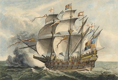
Greetings everyone; Whilst browsing on the NMM website, I came across this picture. It shows the 'Great Harry', one of Henry VIII's favourite ships, and it looks quite impressive. The painting is listed as by Hans Holbein, who was court painter to Henry, so he should have known what he was painting. I have never seen this before, and I can't imagine that it would not have been shown in all the books I have read that cover this period. My question is: could this/is this really by Holbein? And if so, why has it been so overlooked? Or is it much later? If the latter, why would the NMM list it as by Holbein? Maybe this is a different Hans Holbein. There are no bonnets on the sails, for one thing. It is PY9170 on the NMM's inventory. Any thoughts very welcome. All the best, Mark P
-
Hi Mike; Thanks for the picture and the discussion. I am sure you're right about it being someone's job to keep an eye on these coils. One other point that might be relevant is that in the Royal Navy, the sailors stationed in the tops were normally some of the most experienced members of the crew. They would undoubtedly make a good job of coiling a rope. The same was probably true in the US Navy. Happy modelling!! Mark P
-
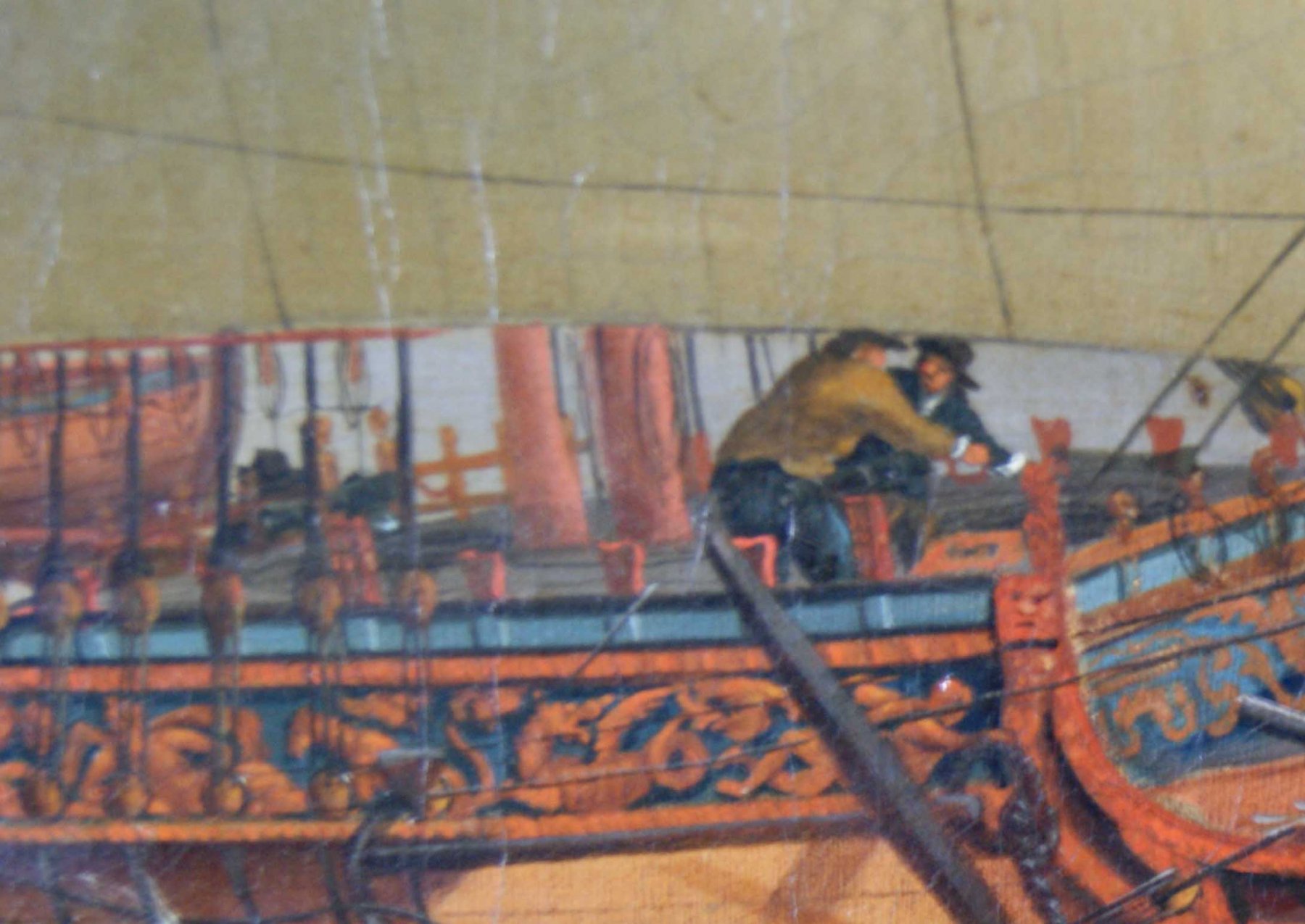
Greetings gentlemen; The term 'belays to itself' is only used here in connection with ropes which would not be needed urgently if the sails needed handling suddenly: specifically in this instance the halyards, which are only needed to raise or lower the yards, and the staysails. Concerning the coils of rope on the deck, the longer ropes were coiled on deck during use. For instance, the sheet or tack from opposite clews of the sail, when close-hauled, would mostly be inboard. I have a copy of the rigging warrant from HMS Monarch from 1765, which lists the lengths of rope and the blocks and fittings issued for all the rigging. For the main sheet, this is 100 fathoms, giving 50 fathoms (300 feet) per side. Some of this may have been spare, but the rigged sheet needed to be twice the width of the mainsail, and then some, which is still a lot of rope. So much rope would make big coils, whether on deck, or perhaps hanging from cleats or kevels or some other fitting. The picture below shows a view of the forecastle of the 'Royal Caroline'. It is not easy to see, but next to the sailors you should be able to make out a large, darker patch. This is a coil of rope laid out on the deck. There is another, smaller one just abaft the galley chimney. This would seem to show beyond any reasonable doubt that large coils of rope were laid out on deck during sailing. All the best, Mark P

-
Hi Mike; I would follow your instinct with regard to the halyard in the top, and go with frapping turns around the tackle itself. I have always interpreted 'belays to itself', as meaning just this. Incidentally, it is the same method used to keep the gun-tackles tight when the guns were stowed. Concerning the halyard falls belayed to the sheer-pole, I would do exactly that, and wrap them around the sheer-pole. This was, after all, a very strong anchorage point, and halyards were normally carrying a lot of weight. Before the use of sheer-poles, halyards for upper yards were often belayed around the lanyards between the shroud deadeyes. Shroud cleats were more used for ropes with lighter duties, for example furling the sails. All the best, Mark P
-
Evening Davyboy; In the 17th century they were made of iron. Anthony Deane experimented with lead cladding to protect ships' bottoms from worm and fouling, but he had to give up due to the electrolytic reaction of the different metals in seawater (all metal fittings near the lead corroded rapidly) In the last two decades of the 18th century, the move to coppering of ships' bottoms made a change to something non-ferrous essential. Gudgeons and pintles were then made of 'mixt metal', bronze to us, which is an alloy of around 90% copper and 10% tin (the tin makes the copper much harder and resistant to wear) The gudgeons and pintles for 'Hannibal', a 50 gun ship of this period, weighed in a 1 1/4 tons. Keel bolts, I believe, were made of copper, not bronze. All the best, Mark P
-
Greetings Druxey; Thank you for your post. It does help. So 2'2" is the height. I hadn't thought of checking in Caruana's book, as I thought his carriage drawings were a little later, for the Blomfeld pattern guns. Thanks for the 'like' Chuck. All the best, Mark P
-
Greetings gentlemen; Of some relevance here might well be the fact that quite a few draughts of various Royal Navy vessels, and a contract I have a copy of, for the building of a 74 gun ship, all show or describe a crutch located on the taffrail, which was for the securing of the boom when sail was furled. Whilst this is not perhaps for the gaff, the gaff could then be supported simply by lowering it on top of the boom (the crutch, by the way, was not located centrally on the taff-rail, but on the quarter. All the best, Mark P
-
Greetings fellow modellers; I have some photographs of a pretty comprehensive printed sheet from the archives of the Science Museum in London. This specifies a load of mast, yard, block and rigging sizes, and details of cannon, anchors and cables for all classes of vessel down to 14 guns. In the title, it says these are all 'According to the last establishment'. The Museum has listed it as from 1812, but it can be dated reasonably accurately as much earlier, by the following items: It states that Victory , only (ie amongst first rates) has 32 pdr cannon on her gun-deck (all the others had 42 pdrs) This change was made by Admiral Keppel in 1778, so the sheet must be after this. It further states that Triumph and Valiant have 24 pdr cannon on their upper deck. These were both 74 gun vessels, and by 1787 they had been fitted with 18pdr cannon on their upper decks, as was normal for other 74s. The sheet must therefore pre-date 1787. The sheet would seem, therefore, to have been compiled between 1778 and 1787 (and it makes no mention of carronades, either) I am fairly certain, but not absolutely certain, of how to interpret part of the description relating to gun carriages, and wonder if anyone here can back me up/correct me. For a 32pdr carriage, the following dimensions are given: (items 4,5 & 6 are the same as the bore of the cannon) Length of carriage 6'1" Height to trunnion bed 2'9" Weight of completed carriage 9 cwt (nearly half a ton!) Thickness of brackets 6" Thickness of trucks 6" Holes in the trucks 6" Breadth of the brackets 2'2" Spread of the brackets in the breaft, in the clear 1'6" Spread of the brackets in the train 2'0" Length of the axletrees 4'9" Diameter of the fore trucks 1'7" Diameter of the hind trucks 1'4" Diameter of the axles 5 7/8" The spread of the brackets, referred to as 'in the clear', means the gap between them, so they are 1'6" apart at the front ('breaft') and 2'0" at the train (rear, or hind, end) What, therefore, can the breadth of the brackets indicate? I think it must be their height, but can anyone think of anything else? (there is no other figure given which might be the height) All the best, Mark P
-
Hi Steve; Brian Lavery's book, 'Nelson's Navy' sub-title 'The Ships, Men and organisation 1793-1815' has significant chapters and information on all ranks of Naval personnel. I think that you will find a lot here. Happy speaking! Mark P
-
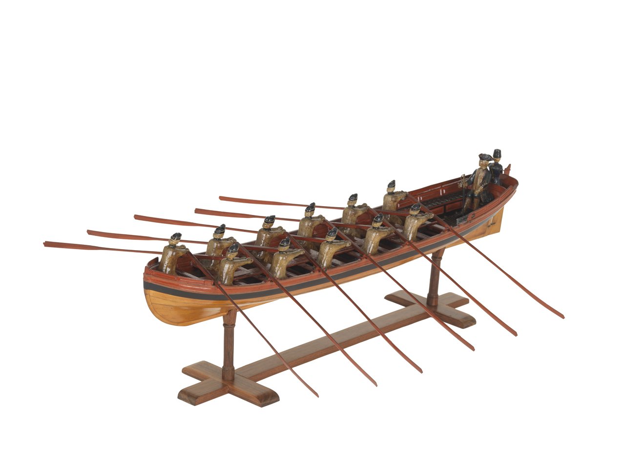
Hi Richard; This is not unusual, but actually quite normal. The rower would sit on the opposite side of the boat to his 'oarlock', to give him more leverage to pull a longer oar. The topmost strake was actually made in a number of removable sections, and known as the 'wash-strake'. The gaps between the parts of this formed the openings for the oars. The wash-strake sat on top of the gunwale, and slotted into short vertical pieces projecting above this latter, and known as 'thole-pins'. These reinforced the openings against the force exerted by the oars when swung back and forth. See also attached picture, which shows a contemporary model of an Admiral's barge in the NMM collections. It may take a moment's looking to become clear, but each rower is seated on the opposite side to his oarlock. Note that there are no wash-strakes in this picture, except in the bows & stern, in which case they are known as wash-boards. All the best, Mark P

-
Hi there; Could it be a fixed length rope to prevent the jib being hauled out beyond a certain point when it was being set? All the best, Mark P
-
Hi Bluto; In your rigging drawing the topmast trestletrees appear to be about half the length of the lower ones. It would therefore seem reasonable that the trestletrees should be likewise. Lees states that from 1769 the lower tops were 1/3 of the topmast length in their athwartships dimension, and 3/4 of that for their fore and aft dimension. All the best, Mark P
-
Greetings Bluto; In Lees' Masting & Rigging, he gives the length of the topmast trestletrees as 3 3/4" to every foot of the topmast's length; the depth as 1" to every foot of the trestletree's length; and its breadth as 2/3 of the depth. For the crosstrees, these are 1 2/3 of the length of the trestletrees; the depth is 7/8 of the trestletree; and the breadth is as the trestletrees. My only caveat is that in his illustration of the topmast top, the crosstrees don't look as though they are as deep as 7/8 of the trestletree, more like about 3/4. All the best, Mark P
-
Harpin
Mark P replied to piratepete007's topic in Building, Framing, Planking and plating a ships hull and deck
Hi Pete; Thanks for adding to the information already here. An interesting article, but I am a bit dubious about one of Kenchington's conclusions: that the horizontal joint was used to prevent the spreading of the frames. The keelson was one of the best placed timbers in a ship to resist hogging, and this had horizontal joints. All the best, Mark P -
Harpin
Mark P replied to piratepete007's topic in Building, Framing, Planking and plating a ships hull and deck
Greetings Druxey; I too believe that the wale timbers tapered in thickness towards the stem, so that by the time they reached the rabbet, they were the same thickness as the planking above and below the wales. I agree with you also that any cross-grained timber would have been avoided at all costs. However, I cannot think of a different reason why the planks of the wale at the bows should be called 'harpins', unless they bear some resemblance to the temporary harpins, which all sources I have ever read agree were sawn to the necessary curve. The use of compass timber (ie timber which had grown in a curve, and so avoided cross-grain) was presumably necessary for the temporary harpins, and so may well have been available for the wale planking also, although obviously in thicker pieces. One counter to this is that compass timber was not available in long lengths, so there would be a necessity for a joint reasonably close to the stem. This would then introduce a weakness, and so I imagine would have been avoided. Another interesting point is that the excerpt from Falconer, quoted above, actually states that the wale timbers, or 'harpins' in this area are thicker than the rest. I wonder if he is referring, rather anachronistically, to the practice of building the wales as two large planks, with a space between them filled with thinner planking, which was largely obsolete from around 1715 onwards. I can imagine that the ends of these wale timbers would be thickened to form a small knee (as indeed the temporary harpins were formed) which rested against the stem. The only other explanation I can think of is that the planking in this area, being harder to fit/make, was distinguished from the other planking by giving it a name; and that the name adopted was derived from the timbers, the temporary harpins, which the wale planking replaced. All the best, Mark P -
Harpin
Mark P replied to piratepete007's topic in Building, Framing, Planking and plating a ships hull and deck
Hi Pete; I was thinking more of the temporary harpins being replaced by solid planking. The temporary ones are described and shown too often on models for there to be any doubt that they were much smaller than the wale timbers. All the best, Mark -
Harpin
Mark P replied to piratepete007's topic in Building, Framing, Planking and plating a ships hull and deck
Hi Pete; Thank you for raising an interesting point. This may relate to the difference between ribbands and harpins as temporary supports. This is that the ribbands were bent, but the harpins were sawn to the correct curvature. Due to the curvature required at the bows, it is possible that the planking of the wales was sawn out (from compass timber) rather than steamed and bent. I am not aware of what the limits of steaming were in practical usage, but as the wales were often of a considerable thickness, it is possible that steaming would not make them pliable enough, and sawing became the best option. However, this is only speculation on my part. It would, though, make sense of William Falconer's paragraph quoted above. All the best, Mark P -
Greetings gentlemen; There are obviously two opposing points of view in this debate, which have been laid out in the preceding posts quite thoroughly, and with some sound-seeming justification behind both. I would think that either method can be taken to an extreme if applied too dogmatically, and the result would then perhaps be pleasing to few who see it. My own view is that the skill and experience of anyone restoring old artefacts would need to be combined with a sympathy for the subject which would temper their enthusiasm and avoid either extreme. My experience of restoring historic buildings has led me to the conclusion that extreme points of view on the 'conserve at all costs' side of the debate tend to come from people with a secure remuneration package. Those who make their living in a less guaranteed manner tend to be more moderate as they are less willing to risk the damage to their reputation which could arise from their work being perceived as controversial. Maturin makes the point that he has walked away from potential work as the brief was not to his liking. In reality, this is a choice that can only be taken by someone in the fortunate position of having something else to turn to (or a private income!) Having walked away, though, the job would then, I imagine, be offered to someone more likely to comply with the commissioner's wishes, who may well carry out the work with less skill or feeling for the artefact's origins and long-term survival. I guess the main conclusion is that there is no way to please everybody; no absolutely right or wrong way of doing it, only a variety of opinions. And this variety will continue to exist, even if the actual opinions become, in the future, different to those expressed above. All the best, Mark P
-
Greetings gentlemen; Some very interesting points have been raised above. I have the NMM draught of 'Tremendous', a 74 launched in 1785. She has exactly the same arrangement of scarphs in the keelson as Wayne has drawn above: 1,2 - 4,5,6, with 3 obviously fitted last. Splitting this into work for two gangs makes sense. Shipwrights were paid in instalments for the work, with each payment related to the completion of a recognised stage in the building. I am not sure of all the stages, but I believe that the laying of the keelson was the final part of one of these. In which case, quite possibly the final part of the keelson was known as 'the money piece' (or the 'let's all go down to the tavern' piece!) All the best, Mark P
-
Hi Alex; Thank you for your reply. I just like to broaden my knowledge whenever possible, and I have not seen a margin plank joined like this, although that most certainly does not mean anything much, as there are a great deal of things I have not yet seen! Thank you for compiling your log, and sharing so much with us. I wish you a rapid and enjoyable completion of your project, which is a joy to look at, and which I will look at many more times yet to come. Druxey, I appreciate your thoughts, and I agree with you about the waterway, but I am assuming that the waterway is the darker strip of wood which will be partly covered by the spirketting. All the best to you both. Mark P
-
Hi Alex; A very nice job you have made of her indeed. The quality of the work is very high. Tapering deck planks look so good. I am intrigued to know if the scarph joints in the margin planks on the quarterdeck and forecastle are your own thought, or is this based on an example you have seen. All the best, and happy modelling. Mark P