HOLIDAY DONATION DRIVE - SUPPORT MSW - DO YOUR PART TO KEEP THIS GREAT FORUM GOING! (Only 13 donations so far - C'mon guys!)
×


Mark P
-
Posts
1,770 -
Joined
-
Last visited
Content Type
Profiles
Forums
Gallery
Events
Everything posted by Mark P
-
 Hi jbshan; Frankie hasn't signed a written agreement not to infringe copyright rules! If the NMM thinks that I am overstepping the mark, my research opportunities could be drastically reduced. Herewith another couple of images. I imagine that the grey roof to the companionway in one is a sheet of lead; especially as it functions as a step to reach the cabin roof. The only ones that show areas of deck have already been posted at the beginning of this post.
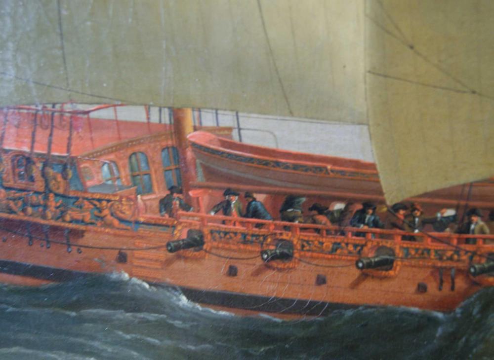
-
Greetings Gentlemen, and thank you for the comments. Druxey, I will see what I can post. As I understand Crown copyright, photographs can be posted on password-protected websites for research and education purposes. However, I only really took photos of details, as the light was poor, and the exposure time long. I will try to post something more, but the best shots of the decks are the two above. Also, I am not sure exactly who is the copyright holder of the Cleveley painting. I imagine it is actually the NMM, and not Crown copyright. I have a digital image of this painting from the Bridgeman Library, but it is not possible to zoom in as close as I was when I took the photos. Doreltomin, your comments are very helpful. I knew that the stove pipe for the Royal Caroline was almost certainly copper, as I have found a mention of a copper chimney, but I assumed the mast was painted, and the chimney also to match. Thank you for adding your knowledge to this post. As they are both always shown as pink, in paintings from different periods, it was probably part of the crew's duties to keep them polished. Are you able to give any sources for documents that describe the painted canvas deck covering in more detail? I would be very glad to find out more about this, as even if it is about Stuart period yachts, it will be very relevant as a precedent (some of those yachts survived well into the 18th century, as I am sure you are aware) I have read about metal mast funnels being used in later periods to protect mast heads from chafing from the shrouds, etc, but not of their use at the base of the mast. I will be carrying out more research at the National Archive at the end of the month, looking for more information about Royal Caroline. Hopefully this will turn up something more about this topic. Again, many thanks for your input. Dwaing, presumably this canvas was of a much finer weave, with a smoother surface. Was it painted with size, or a similar compound. Thank you all again, gentlemen. All the best, Mark P
-
Hi Banyan; I have had a look in Lees and Marquardt, and both of them say that the reef tackle fall led down to the deck. All the best, Mark P
-
Hi Mark; Thanks for the thought. I don't think it's intentionally off-colour, as the hull planking is the correct colour. Besides which, the decks are not really a noticeable part of the painting. It is not until you zoom in close that it becomes obvious that something is strange. All the best, Mark P
-
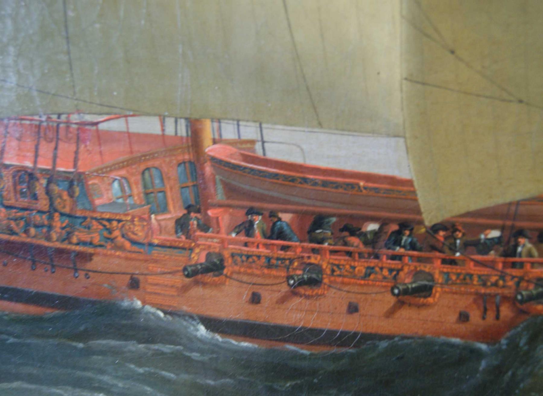
Hi everyone; Thanks for the comments. The cabin amidships is part of the Royal suite of cabins, and the roof is indeed painted red. Some paintings show a couple of figures standing on this cabin roof, presumably including the captain, who otherwise would not have been able to see the rest of the crew very well. Regarding the shadow, I agree that it is possible when looking at the aft deck that what we are seeing is the shadow of the sail (it can't be the shadow of the bulwarks, as the sun is on the starboard side: see the anchor shadow) However, the entirety of the fo'c's'le deck is the same grey, with one area nearest the viewer a slightly lighter colour. There is a change of grey colour just this side of the mast and the galley chimney (yes, these are pinky-red! They are shown this colour in every painting, although the bottom of the mast was this colour only for about the first six feet). This shading of the grey area seems to me to indicate that most of the fo'c's'le deck is in shadow, but not the part nearest the viewer. So it cannot be shadow that is responsible for this grey all over the fo'c's'le deck. And as the sail is braced hard round, it would be impossible for it to cast a shadow on the entire deck. It can be seen that the coat worn by one of the crewmen is part in sunlight, part in shadow. So any deck to his right would be in sunlight, hence the change in shade near the mast. The hull of the ship's boat, whilst indeed partly shadowed, is still noticeably browny-gold, not grey. The adjacent deck is a very different colour. I am sure it is not shadow we are seeing. All the best, Mark P
-
Hi Matrim; thank you for the reply. Everybody develops their own way of working, and if it works well, that's all we need. I thought that you would probably have your own system to avoid confusing frames, as it seems to be necessary. I had not really thought of using a temporary colour change. I'll keep it in mind as it might well be useful for other things. All the best, Mark P
-
Hi Matrim; Excellent draughting! One thought that might be of interest: when I have been copying/drawing a draught, I make each station line a different colour. Then, when the lines are drawn on the body plan, at the outer edges, where they overlap a lot, it is easier to distinguish which is which. I also make any datum marks on the body plan the same colour as the station line to which they belong. All the best, Mark P
-
One further thought: Royal Caroline had her sea trials in early 1750, before she was finished. Quite possibly the painting shows her during these trials (there is no Royal Standard at the masthead, so the king was certainly not on board at this time) and perhaps the deck needed to be covered as it was not completely caulked, or the seams had not yet been filled off with pitch. All the best, Mark P
-
Hi Mark; I think you slightly mis-read my note, as it says she was months on from being launched, ie after launching. I will try and avoid such potentially misleading sentences in the future, and make it clearer. All the best, Mark P
-
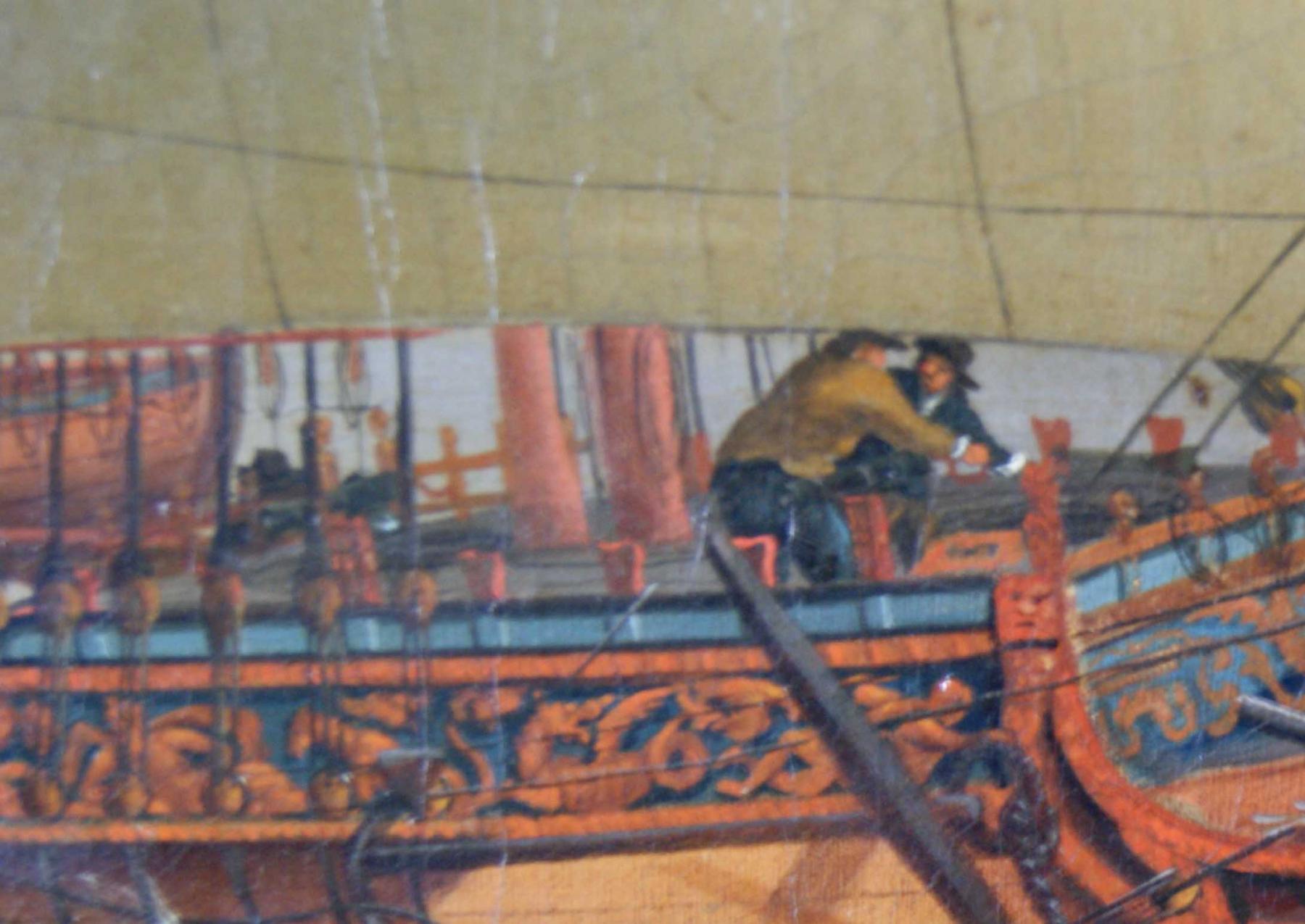
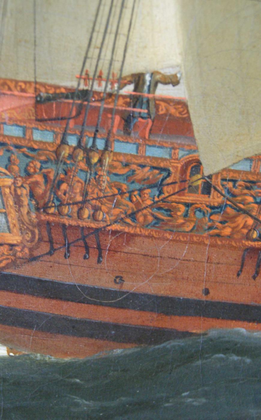
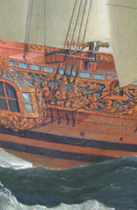
Hi Gentlemen, and thank you for your interest. Druxey: the carved and gilded frieze of figures is well-detailed on the painting, and is a very close match for the draught of Royal Caroline which was made by Af Chapman, who was in the Deptford area close to the time of her building. I have also found an itemised bill for decorating the Royal Caroline, which lists Mr Cleveley as responsible for painted panels, of shipping and other themes, in the King's rooms, and for re-furbishing the panel on the buffet, presumably removed from Caroline's predecessor. It can therefore be a safe assumption that the picture of Royal Caroline painted by John Cleveley, from which the photos above are taken, was painted by him (in 1750) based on a great degree of close personal knowledge of her appearance. You may also remember some earlier posts about a seat of ease at the beakhead, which is also drawn on Chapman's draught. It is just possible to make this out on the painting, although not clear; however, there is another painting of her by John Cleveley, in which the seat of ease is quite clearly shown. Fatfingers: thank you for the idea; teak does go silvery over time, as do many other woods left to weather. I am not sure if timber from the Far East was being used at this time, though, in English shipyards, but it is something to consider, and a possible explanation. A point against this is that the decks were almost certainly scrubbed (swabbed) every day, and at the time of the painting, Royal Caroline was still only months on from being launched, so the decks would not have been very old. All the best, Mark P
-
Hi Frankie; Thanks for your thoughts, and herewith the requested photos. Apologies for the somewhat poor image quality, but these had to be taken without flash, so with a 1/4 second exposure. My first thought on seeing this was that it was the shadow of the sails, but some areas of the deck appear in darker and lighter shades of the grey colour. I fully agree with you that the decks of a Royal Yacht are likely to have been holy-stoned (comes from the men being on their knees, as in praying) even more assiduously than on a normal Navy vessel, which was normally every day. This kept the deck planking pale, not allowing dirt to stay there. I also concur with your observations about the likelihood of canvas trapping moisture, and not lasting long, but I cannot think of anything else it could be. I don't think that it is a fading of the oil paint, either, as the topside timbers are quite clearly the correct colour, and deck planking would normally be lighter than this. Incidentally, the darker smudges near the crewmen on the fo'c's'le are coils of ropes laid out on the deck (no belaying pins here!) And another incidentally: the black rail on the fo'c's'le is, I believe, not the final finished colour. I think it is the first stage in painting and then gilding (although red is normally the colour of the coat directly under the gilding) However, Royal Caroline went for her sea-trials, and even for her first trip with the King aboard, with quite a lot of her gilding and painting un-finished. As this painting is dated 1750, it seems quite reasonable to assume that it shows her in this state. She was launched 2 months before the end of 1749, but then had to be fitted out before going to sea. All other paintings show her with gilded rails. Anyway, any suggestions as to what this grey-coloured deck might be would be most happily received! All the best, Mark P


-
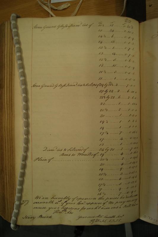
Hello everyone; I thought that my fellow modellers might be interested in the following document, which I found at the National Archive in England, whilst searching for a somewhat different subject. This lists the prices, sizes and quantities of a delivery of glass made to Deptford Dockyard in November 1750. The biggest pieces are quite large: 31" x 21 1/2", 3no. Their rarity and value is reflected in their price, £7.0.0 each, which is many times higher than the smaller, more numerous pieces. Lower down in the list are some pieces of mirrored (silvered) glass, some of which are again quite large and expensive. Clicking on the image should make it larger. If not, right-clicking on the image should bring up a menu with an option to 'open image in new window' option which makes it larger and easier to read. All the best, Mark P
-
Hi Keith; I think you will find that in the days of sailing vessels a clove hitch was used where the ratlines crossed the inner shrouds, but an eye-splice was formed in each end and this was seized to the outermost shrouds. All the best, Mark P
-
Greetings everyone; I am researching the Royal Caroline of 1749, and as part of this I have viewed the original of the painting which is used as a frontispiece in Sergio Bellabarba's AOS book about her. As his illustration is in black and white what I will be describing is not obvious, but it is possible to view colour images of this painting for anyone really interested. Anyway, in this painting, although parts of some of the decks are visible, no deck planking is shown. instead, the deck appears to be covered with a uniform grey-coloured something. My first, and so far only, realistic guess is that it is painted canvas. This grey covering is visible on the quarterdeck, where the Royal passengers would mostly appear, so it may be related to them, but it also appears on the forecastle, where they certainly would not normally go. The upper deck in the waist cannot be seen, but it would seem a fair assumption that it was similarly treated. Could it be purely decorative, or could it be as a means of aiding important feet to avoid slipping and sliding as the vessel heeled and pitched. Before I go and pass many hours wading through her log-books in an effort to see if anything about this is mentioned, I wondered if any other members here might know anything about it. All the best, Mark P
-
Dear Wayne; Such a resource as you describe would be invaluable to many modellers. I would certainly be a visitor. The thought of constructing a model that subsequently turns out to contain errors which could have been eliminated by deeper research is not pleasant. The availability of additional resources would be most welcome. Listing in the way you outline seems to be best to me. I could also perhaps help in some small way, if you need anything from England. Please feel free to ask if you think of anything that may require some on-the-spot research. All the best, Mark P
-
Caroline's bottom
Mark P replied to GrantGoodale's topic in Building, Framing, Planking and plating a ships hull and deck
Hi John; That sounds to me like a very reasonable theory. I have read about the method of protecting the ship's bottom by hammering in thousands of copper nails so close together that the heads overlapped, They would indeed have looked like peas once they turned green. In the Royal Navy, pea soup was a popular meal, so there may well have been only a short distance between seeing the effect on the ship's bottom and naming it after a common food. All the best, Mark P -
Hi Druxey; I'm with everyone else on this. A fine inspiration to all, and a very informative, instructive and pleasure-to-read build log, with a lovely model at the end of the trail! All the best, and many thanks for taking the trouble to share this. Mark P
- 641 replies
-
- 4
-

-
- greenwich hospital
- barge
- (and 1 more)
-
Caroline's bottom
Mark P replied to GrantGoodale's topic in Building, Framing, Planking and plating a ships hull and deck
Hi Druxey; I have never heard of that one. I will keep an eye out for any references in the future. All the best, Mark P -
Caroline's bottom
Mark P replied to GrantGoodale's topic in Building, Framing, Planking and plating a ships hull and deck
Thanks Robin; All the best, Mark P -
Caroline's bottom
Mark P replied to GrantGoodale's topic in Building, Framing, Planking and plating a ships hull and deck
Hi Grant; 'White stuff' was used to cover the ship's hull below the waterline. It was intended for use in the tropics, where the shipworms were more active. It was more expensive than the 'black stuff' which was used for ships in European waters. However, most models depict the ships with a white bottom, as it is much more attractive. In the case of the Royal Caroline, she is shown in several paintings by John Cleveley the Elder, and where her underwater hull is visible, it is white. As Cleveley was renowned for the accuracy of his paintings (also, he was a former shipwright at Deptford Dockyard, and was there at the time that Royal Caroline was built there) I would take that as sufficient authority to paint her bottom white. As for coppering, this was only introduced widely in the early 1780s, so would not have been used at the time of Royal Caroline's launch or for much of her career (not until after she was re-named the Royal Charlotte in 1761) All the best, Mark P -
Hi Bear; Those are some very realistic-looking timbers you've made there. Congratulations! Balsa wood is a very good idea for them, so that the soft grain can be brushed away. That's one to file away in the old memory for use if I ever build a dock of any sort. All the best, Mark P
-
Hi Keith; I don't know much about launching or docks in the early years of the 16th Century, but if Mary Rose was built in a dry dock, then if later practice is a guide to that of earlier periods, she would not have been in cradles. A ship in dry dock was supported with a line of blocks below the keel, and rows of props against the side of the dock to keep her upright. For launching, the dock was filled on a rising tide, and the ship was floated out. Cradles were used on a slipway, which had a bottom that sloped down to the river, and ships were launched by sliding them into the water, with the ship in two cradles which slid on timber rails. All the best, Mark P
-
Help in Identifying an Unknown Tool
Mark P replied to BANYAN's topic in Modeling tools and Workshop Equipment
Hi Pat; Over here in England, that is what we call a mortice guage. As Rick says above, it is missing a block. This block could be moved independently of the pins, so that either one pin is just tucked into the face of the block, in which case only one pin scribes a line, or it can be set away from both pins, so that a double line can be scribed. Without the pins and the block, it is probably only good for a small vice, as you say. All the best, Mark -
Hi Siggi; Thanks for posting that excerpt about the washing etc. Very interesting. There were some very cruel captains. Piggott, of the 'Hermione,' who was so bad that his crew murdered him, was an extreme example. On the other hand, even the Admiralty could be amenable at times. When the crews of the ships at Spithead mutinied, without violence, in 1797 (although they made it clear that if the enemy came around they would return to duty) their quite reasonable demands were agreed to. It was only later, when crews in other bases tried to extract more concessions that things turned nasty (although this seems in great part due to the character of the ringleaders) As with so many things, I think it all comes down to the fact that there are many different types of people, and each behaves differently. All the best, Mark P
-
HMS Naiad 1797 by albert - FINISHED - 1/48
Mark P replied to albert's topic in - Build logs for subjects built 1751 - 1800
Greetings Albert; I have just found your log, which I will now follow with great interest. Your work is of a very high standard, beautiful to look at, and shows again what can be achieved by those who take care and pride in their models. I am in agreement with so many others' posts on another thing: I too am envious of your so tidy workshop! Every time I look at such great craftsmanship I just can't wait to get started on my own project (still finishing off the workshop, seems to be taking forever!) All the best, Mark P