HOLIDAY DONATION DRIVE - SUPPORT MSW - DO YOUR PART TO KEEP THIS GREAT FORUM GOING! (Only 20 donations so far - C'mon guys!)
×


Mark P
-
Posts
1,770 -
Joined
-
Last visited
Content Type
Profiles
Forums
Gallery
Events
Everything posted by Mark P
-
 Hi Mark; Just one thing that you might not have noticed: the wales on the model are not planked with anchor stock, or top and butt, but with 'hook & butt'. I have attached a sketch of this. All the best, Mark P Bellona wale drawing.pdf
 -
One further thought: Could this refer to large iron staples set horizontally into the bulkheads of the storage rooms in the hold, adjacent to the scuttles, to allow men to climb down into the store. I'm thinking of the Bread Room, Fish Room, Steward's Room, & Spiritous Liquors Room (and please, don't anyone suggest it might be the magazine ) Similar to the steps set into manholes to allow men to climb down inside them. I will look at some deck plans to see if this might work. All the best, Mark P
-
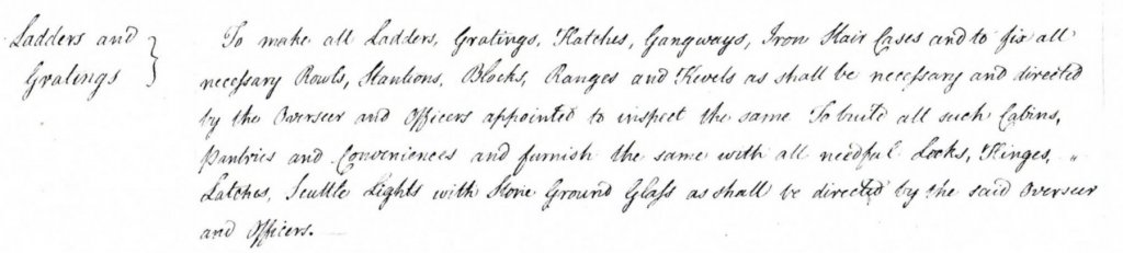
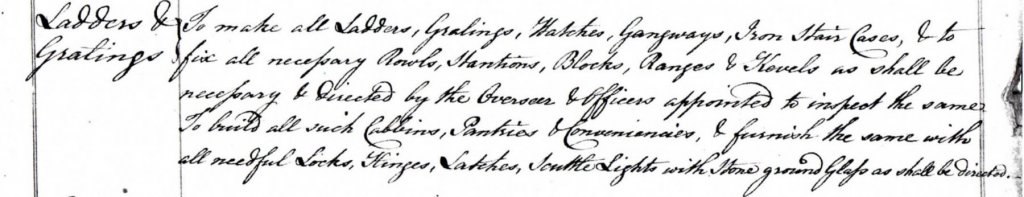
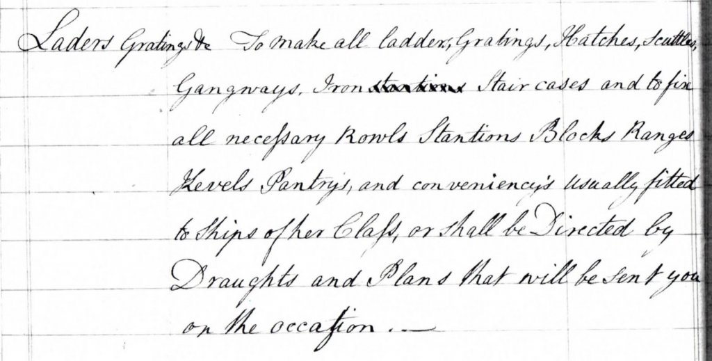
Hi Druxey; Handwritten it is; but completely clear, see below. I have also just noticed that the contract for 'Bombay Castle', dated 1779 (the contract for 'Ganges/Culloden' above is dated 1778) contains exactly the same wording. Interestingly, the one for 'Ganges/Culloden' is in 3 different hands, whereas the one for 'Bombay Castle' is all in one hand. It also occurs in the contracts for 'Culloden' of 1770, and 'Bellerophon' of 1782. Ganges Bombay Castle Culloden, contract 1770 Bellerophon, contract 1782 It might be a standard insertion, but it must have an origin somewhere. All the best, Mark P
-
Hi Mark; Thank you for the reply. The contract is indeed of a pretty standard format, but I've never seen this before. All the best, Mark P
-
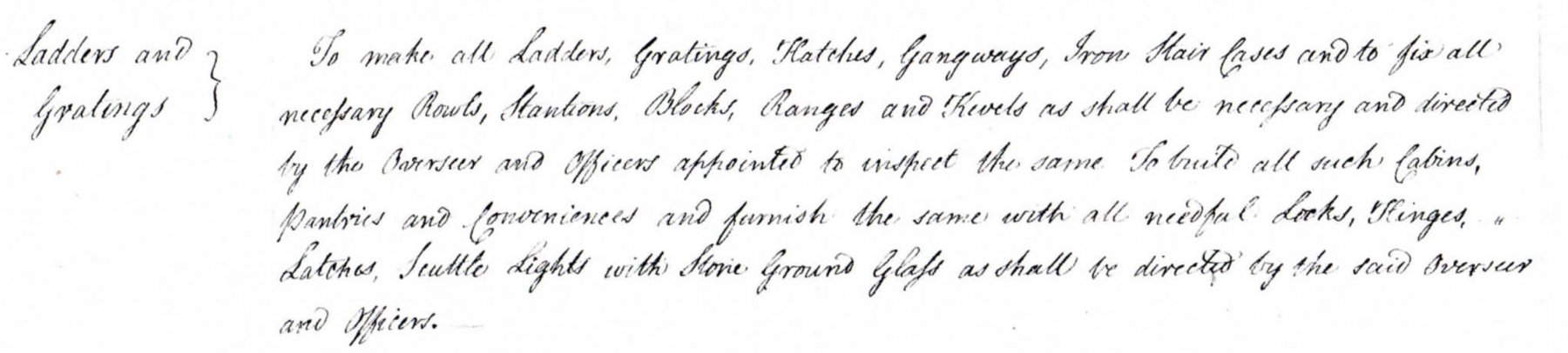
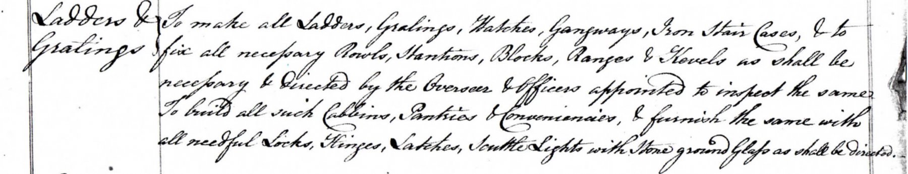
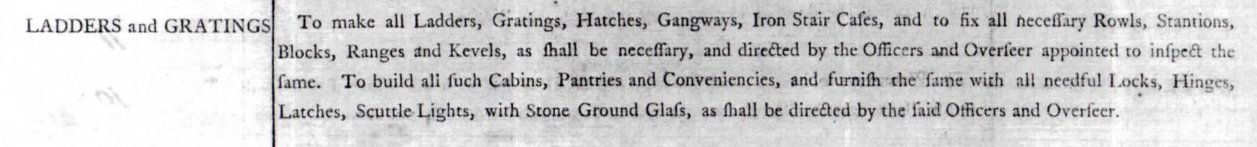
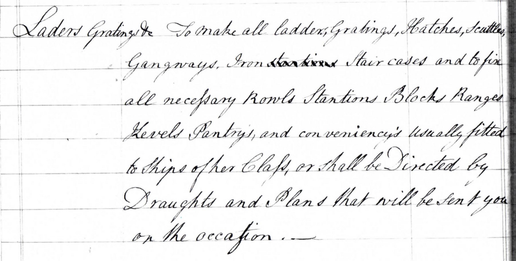
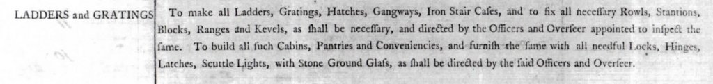
Greetings everyone; I am transcribing the contract for HMS Ganges, a 74 gun ship, dated from 1780 (it might be for HMS Culloden, 1782) and I have come across a puzzling entry: Under the heading 'Ladders & Gratings', it says: 'To make all Ladders, Gratings, Hatches, Gangways, Iron Stair Cases, & to fix all necessary Rowls, Stantions, Blocks, Ranges & Kevels as shall be necessary.' Does anyone have any idea where an iron stair case would be fitted in a 74? I have never seen mention of any such thing in any book or document. An iron stair case would be much more expensive to make than would a wooden one, so if this entry is correct, it must have been an important function which it filled, and would not be used where a wooden one could be fitted. Any thoughts on this would be welcome, as I'm completely stumped. All the best, Mark P
-
Hi Mark; Will she sail away for a year and a day, if you can find an owl?
-
Hi Mark; They are all available as photocopies. Some are hand-written, and some are printed, with the dimensions filled in by hand. They follow a fairly standard formula, but vary slightly in the amount of detail they include. The majority of them were written for ships built in merchant builders' yards, to ensure that they built to the same standards as the Royal Dockyards; but at least one, Culloden 1770, was for a Royal Dockyard. I do not believe that any of these are available online. They are all A3 size sheets. The printed ones are around 24 pages. At least one of the handwritten ones runs to 80 pages (although it includes not much any different; it is just written in a large script; although that makes it easy to read!) They should show up under a search on the collections website under the keyword 'contracts', or 'specifications', filtered to the 18th century. To purchase, send an email to pictures@rmg.co.uk , quoting the ADT number I have given. When I purchased mine, they were bought from the plan store, but the system is different now. They might be available now as a digital download; I do not know. A further item of interest, and apparently a very rare survivor, is ADT0253, a rigging warrant for HMS Monarch, 1765. This lists every conceivable piece of rope for the whole ship: its diameter, length, and associated block type and size. It was used for the issue of rigging stores from the dockyard, when the rigging of the ship was set up after launching. I don't remember ever seeing this referred to in any book, rather strangely, as it is very important for anyone rigging a 74. If you intend to set up rigging, this is invaluable. There were a lot of changes to ships' rigging in the 1770s, but as this warrant is earlier, it would apply to Bellona. All the best, Mark
-
Good evening Mark; Concerning your query for the siting of the wing transom knee, I think that the important word is in the contract reference where it says that the knee is scarphed 'upon the spirketting'. I would interpret this to mean that the spirketting is fixed first, and the knee afterwards, on the spirketting. As you mention above, the spirketting adds to the strength of the ship, and I cannot believe that it would be terminated at the beginning of the knee. Especially as the knee is 16' long, much shorter than a strake of planking would be. It cannot mean upon as in the sense of 'on top of', as the wing transom is not higher than the spirketting. Ed: I have some information from the NMM on the contracts that they hold, and for 74s they have the following: (there may be others I was not told of, though) Saturn, January 1782 (contract dates given here) ADT0102 Elephant, February 1782. ADT0030 Bellerophon, January 1782. ADT0011 Bombay Castle, September 1779. ADT0009 Berwick & Ganges, May 1778. ADT0012 Culloden, Thunderer Class, May 1770. ADT0166 (note that this Culloden is an earlier vessel than her namesake listed below) The contract for Ganges, ADT0012, I have recently suggest to the NMM was actually Fortitude (1778) which has now been agreed by the Museum, and will be re-catalogued as set out in their email below: Dear Mark, I have taken a look at the above contract and my conclusions are as follows: The black dimensions (i.e. the ones the contract was originally written for) – Fortitude (1780), as the only one from the Albion class to be built by Randall in that period. The red ink dimensions (written above the black ink) – This matches the Ganges class of 1779. If we were to assume the Randall builder was relevant to this amendment then the two ships they built from this class are Ganges (1780) and Culloden (1782). The green in dimensions (written below the black ink) – This matches the revived Elizabeth class of 1760. Again, if we assume the builder is relevant to this amendment then the ship here is Defiance (1783). The old catalogue mentions Berwick of the same class, but she was built at Portsmouth. I will make the amendments to the catalogue. I hope that this is of interest. Yours sincerely,
-
Hi Mark; The following is taken from the contract for 'Culloden', 1770: The wing Transom knee to be sided 12 1/2" the fore and aft arm to be 16' in length or to give shift to the after part. the thwartship arm to be 6' 0" to be Bolted with 5 Bolts of 1 1/4" diam in the thwartship arm, and with 7 no in the fore and aft arm, and with two small bolts of 7/8" Diam in the lips of the scarph. The contract for 'Bombay Castle' of 1782 is very similar, except that it adds that the knee is to scarph with hook and butt upon the upper strake of spirketting. All the best, Mark P
-
Hi Mark; Speaking of the wing transom knee, I have copies of several contracts for the building of 74s, and all of them describe the knees to be fixed between the wing transom an the ship's side. If you want some dimensions I will send them over. Keep the project rolling: it's great to follow, inspirational everywhere. All the best, Mark P
-
Hi Tim; There was an official 'establishment' for the issue of tables to Royal Navy vessels. They were issued by the dockyard. I cannot remember where I saw it, though. Don't recall anything about chairs. Sea chests probably filled the duty much of the time, especially in the gun-room, and for at least some of the ward-rooms' inhabitants. I remember also seeing pictures of part of a table recovered from a ship-wreck, but again, I am afraid I cannot remember much else about it. All the best, Mark P
-
Greetings everyone; Thank you to Alcedo for such an informative post, and especial thanks if you are the same person who compiled the spreadsheet linked to it. A lot of work went into this, and it is very kind and generous of you to make it available online. The National Archives at Kew have an original copy of one of these sheets, which I have photographed previously in sections. However, the very bottom has been cut off, removing the date and place of publication and publisher's details. From the detailed information given in the site linked to Alcedo's post, it is clear that it is one of the middle publication series, as it refers to the data as 'according to the last establishment'. It can be dated also by the fact that it describes two items relating to armament of vessels: that the Victory has 32 pdrs on her lower deck (according to Winfield this occurred only between mid 1778-mid 1779 [and after 1805 but this can be ignored here] )and that the Valiant & Triumph only have 24pdrs on their upper decks. As both Valiant and Triumph had been refitted with 18pdrs by 1787 (Winfield) it would seem reasonable to assume that this sheet is a complete re-print of the earlier version with the title altered. EDIT - just noticed that this is stated in the info given in Alcedo's post. Thank you Alcedo for giving me the means to know what it is that my photographs are of. All the best, Mark P
-
Greetings Amalio; I have just discovered your log: absolutely beautiful work! The neatness of your joints and finish is exemplary, something to aspire to at any stage of the craft of model shipbuilding. The differences between Spanish practice and English techniques are very interesting, and looking for them is both absorbing and educational. Thank you for posting so many pictures of your work. All the best, Mark P
-
Hi Michael; One thing which may be of help to you with masts, depending upon what ship you are making: The NMM have some quite detailed drawings in their plans archive, showing how masts were made, all drawn to scale with many sections. These start to appear in the early 1780s, when the supply of 'New England' masts made from single trees was disrupted by American independence. These cover a range of ship types, though all Royal Navy. All the best, Mark P
-
Hi Jim; If I was at an exhibition of local artists' work, and saw your paintings, I would have to buy at least one to take home with me, and preferably more. The only limit would be budget! Lovely atmosphere in your work. Keep on picking up that brush! All the best, Mark P
-
Hi Heinrich; Jaager is completely right in all he says. To answer your question, cut it as soon as possible; it dries more quickly and the smaller thickness is able to release the stresses much more easily. Left as a round section of trunk it will quickly split up at least one side. Cut the planks thicker than the finish size you want. There is always some degree of twisting etc. Season it somewhere with a roof to keep the rain off, but which allows the wind to blow through. All the best, Mark P
-
Hi Lou & Pete; Reading 'The Cruel Sea' made me very glad that I was not around at the time. Hats off and all praise to those who served, including the merchant ships' crews. I have seen some pretty detailed drawings and sections through galley stoves, and the only thing that was normally found inside the chimney was a horizontal fan, which was turned by the rising heat. The rotation of this fan was then used to power the rotating spit. If my memory is not betraying me, this was a feature of the Brodie Stove, which came into use around 1780 (I think) Prior to that, the chimney was just a tube. All the best, Mark P
-
Hi Pete; That seems logical enough. Many of the inboard works draughts, or sheer draughts which show inboard works, also show the stove in some detail. All the best, Mark P
-
Evening Allan; I have more photos of Captain. See the album in the contemporary models in Museums section here. If you would like any of them let me know, and I can pop them on a disk for you and send it off across the pond. I am not sure what photos the Science Museum have. I have seen some of their plans, and Captain was not among them. They do have good contemporary plans, showing the figurehead, inboard works and decoration, of the Deptford 1719, Exeter (Date?) Strafford 1714, & Winchester 1717 which I think were 50 gun ships, although not certain on this. I imagine that these were built to the 1706 establishment. All the best, Mark P
-
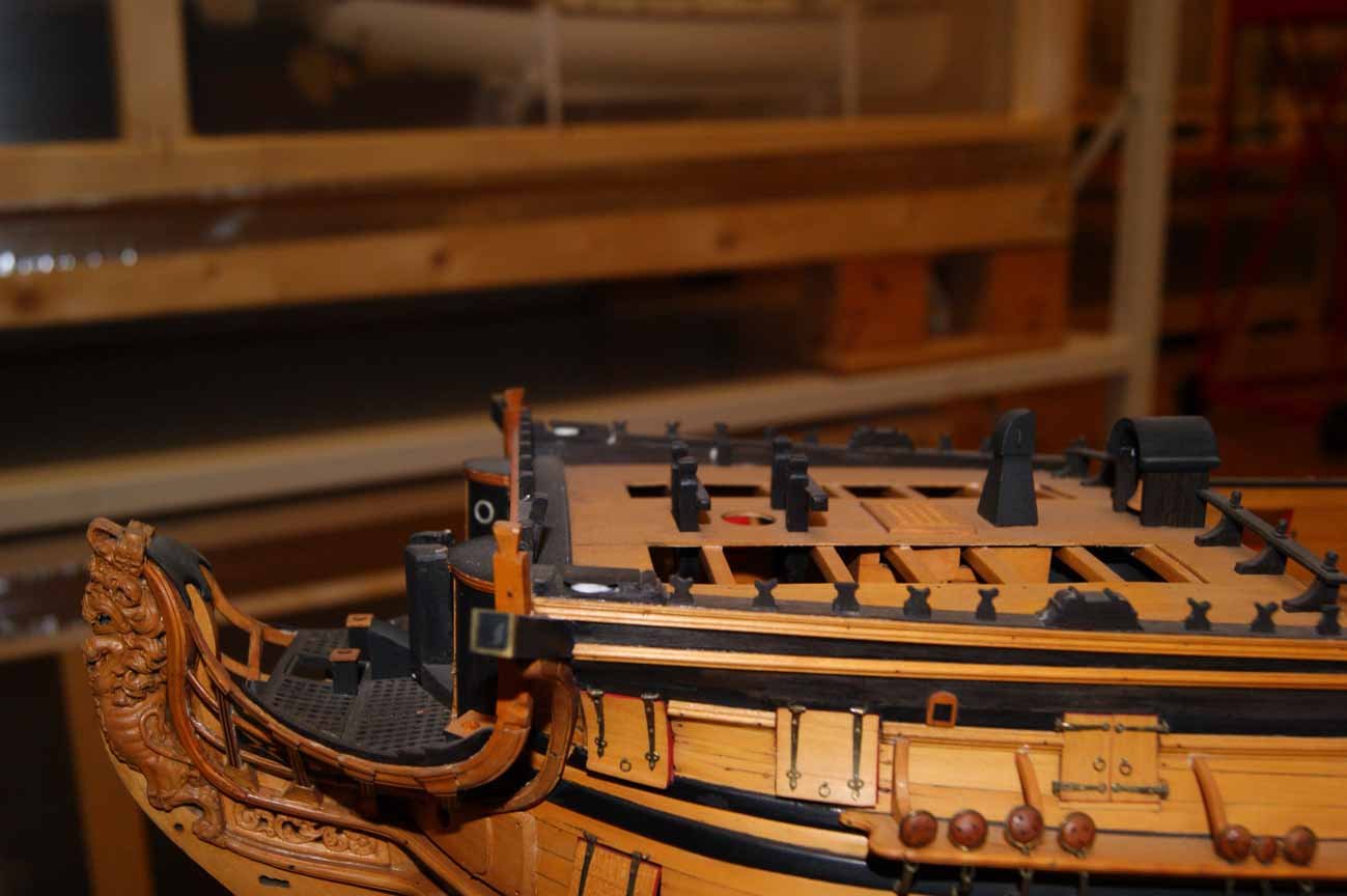
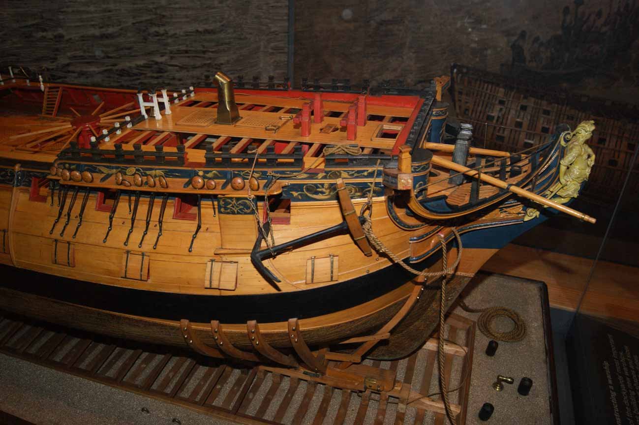
Hi Pete; In the Royal Navy, the chimney flue was normally finished with a section which curved over, so that the discharge was horizontal. This final section could be rotated to point downwind, whatever the ship's point of sailing. The attached picture, of a model of HMS Captain, 1708, in the Science Museum's collection, shows one type, with handles. I am not sure if this one could rotate, or if it was simply lifted off, and turned in 90 degree increments before being put back in place. Second picture is of the well-known model of HMS Bellona, 1760, in the NMM. Her chimney is rounded at the end, so the final bent section could be rotated to any degree desired. I have seen the round type depicted with handles also. All the best, Mark P


-
Stern timber scantlings
Mark P replied to Mark P's topic in Building, Framing, Planking and plating a ships hull and deck
Thanks Allan; Looks like a useful book. I shall have to get a copy. All the best, Mark P -
Stern timber scantlings
Mark P replied to Mark P's topic in Building, Framing, Planking and plating a ships hull and deck
Thanks Wayne; They might be. I don't have this book, as I have (or thought I had) a complete list of scantlings for both the vessels I am currently working on. Only realised there's a bit of a gap when I reached the stern timbers. I have found everything I need in Steel's 'Vade Mecum', of which I have a pdf copy I downloaded from the Bodleian Library in Oxford (which incidentally, is a much better copy than Google's own one) Although he is a bit later, I think that his lists are based on earlier practices, and I can use his scantlings for a 74's stern without worry. All the best, Mark P -
Greetings everyone; Can anyone point me to a good source for the scantlings of the stern timbers in a 74 gun ship, built in the first half of the 1780s. I can find an entry in a contract I have which specifies that the counter timbers should be 10" sided, but no other dimensions are given. Goodwin, rather frustratingly, gives a range of fractions to multiply parts of the stern by to obtain other parts, but he does not give a starting dimension to which I can apply these factors to begin the process. The establishment lists do not mention them either, as far as I can determine. I could guess at them being the same as a toptimber, or fourth futtock perhaps, but that has no basis in fact. All the best, Mark P
-
Frame Dimensions
Mark P replied to ToddM's topic in Building, Framing, Planking and plating a ships hull and deck
Hi Todd; Your drawing is correct, in my experience, although that doesn't cover everything. The sided dimension remained constant for the length of each futtock. the taper was between the inner and outer faces: the moulded dimension. One other point of interest: your drawing shows frame bends, the name for a frame made up of a two sets of futtocks fixed together. As to whether model makers repeat this, it depends upon their patience and how faithfully they wish to replicate full-size practice. As you say, it is a lot of work! All the best, Mark P -
Frame Dimensions
Mark P replied to ToddM's topic in Building, Framing, Planking and plating a ships hull and deck
Good evening Todd; I can't be sure of the Dunbrody in particular, but it was normal for futtocks and toptimbers to taper across their moulded dimensions (L/H side of your picture) and for them to reduce in thickness across the sided dimensions with each successive futtock. This was done to save weight and to enable a wider selection of timber to be used (most long sections of a tree taper naturally) All the best, Mark P