HOLIDAY DONATION DRIVE - SUPPORT MSW - DO YOUR PART TO KEEP THIS GREAT FORUM GOING! (Only 24 donations so far out of 49,000 members - C'mon guys!)
×


Mark P
-
Posts
1,770 -
Joined
-
Last visited
Content Type
Profiles
Forums
Gallery
Events
Everything posted by Mark P
-

Seeking information on determining load waterline
Mark P replied to trippwj's topic in Nautical/Naval History
Dear Wayne; You have put a serious amount of time and effort into researching all this, with many interesting contributions from others added in, and it is fascinating stuff. I had no idea that Matthew Baker was calculating such things as described in this thread. As has been said earlier in this thread, it would appear that Deane's role in all this has been somewhat aggrandised by Pepys. And with regard to your last post, it would be a rather unfortunate merchant who had his customs dues calculated by Mr Humphrey's method. He appears to be considerably off the mark. Would you mind if I printed off this thread to read in more leisurely circumstances? All the best, Mark P -
Hi JB; Yes, it would need three blocks or sheaves per side to work. The use of blocks in a replica vessel does not point to their use in the vessel being copied, unless based on good evidence. From what I have seen in the writings and illustrations about steering ropes, the use of sheaves was common to guide them. This can be seen in surviving vessels: both Victory and Foudroyant are fitted with sheaves. We obviously cannot know for certain either way, unless there is some description or mention in the logs or journals. All the best, Mark P
-
Thank wefalck for posting this. An ingenious little device, with its construction clearly described. All the best, Mark p
-
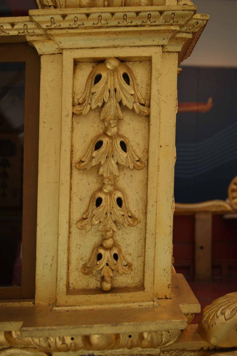
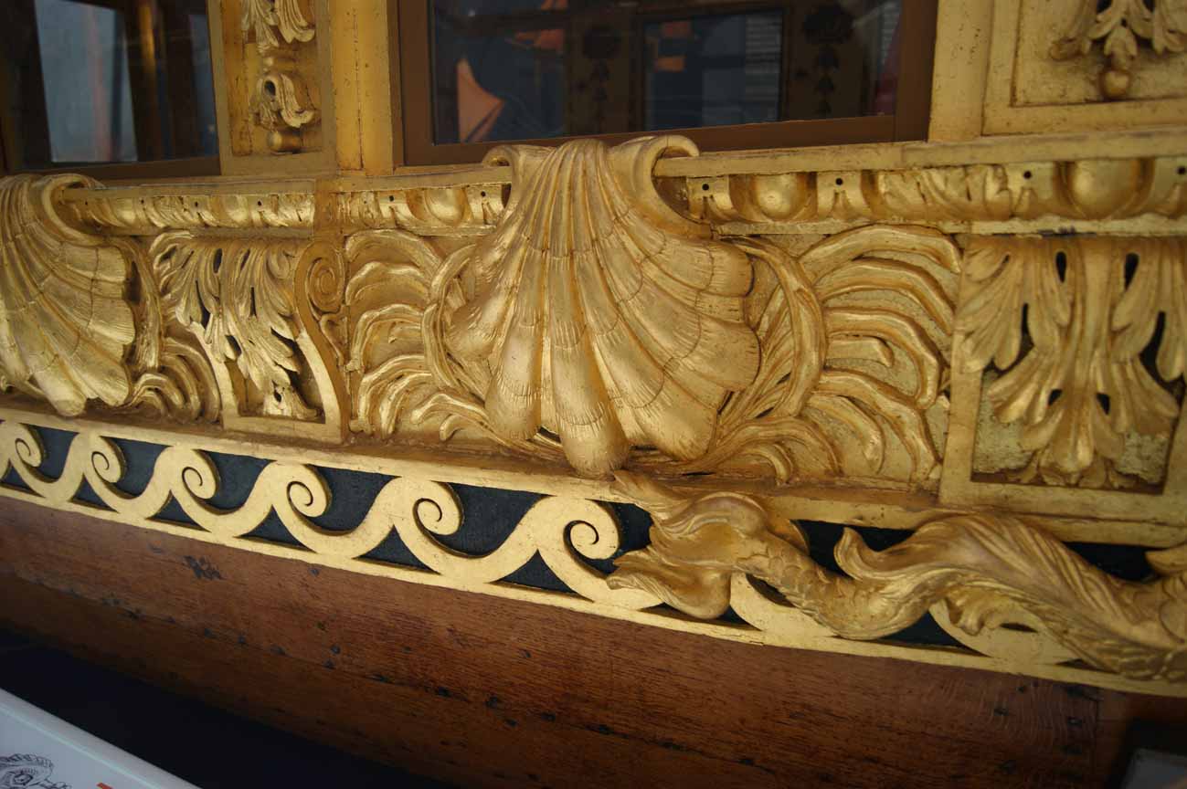
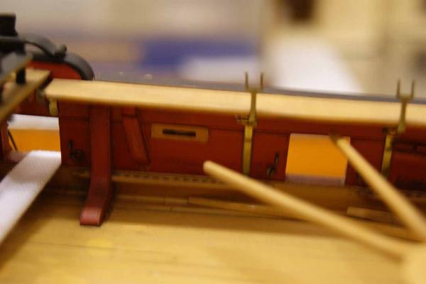
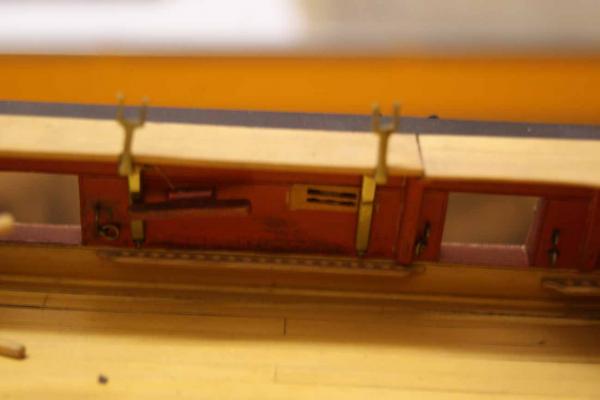
A beautifully constructed model, Druxey. You certainly set a high standard to aim for, which is only for the good. Incidentally, I should be at the NMM on 7th April. I will take some pictures of the underside area of the rowing benches of Prince Frederick's barge, and try to show the balusters supporting them. There may be some additional details there that will be of interest. Incidentally, the cabin on this barge, which is much earlier, has large panes of glazing. I believe that it was made by blowing a large cylinder, and then cutting it along its length and flattening it out. I know this was a technique used, but I am not sure of if it was still current in the period being discussed. All the best, and keep the exemplars coming please! Mark P
- 641 replies
-
- 3
-

-
- greenwich hospital
- barge
- (and 1 more)
-
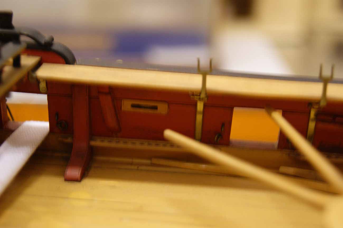
Greetings everyone; A few thoughts strike me on studying the draughts. Firstly, the tiller and sweep are above deck, else they would be drawn in red. Secondly, by virtue of its being located only two-thirds of the length of the tiller, the sweep does not extend the full width of the quarter-deck, allowing free passage past it on the outer part of the deck. With the helm hard over, the tiller would reach the end of the sweep, and the gooseneck would be tight to the bulwarks. It would seem to me, therefore, that the function of the sweep was to support the tiller from below, with the tiller riding along the top of its curve for the full length of its travel. There was probably a lug fitted to the underside of the tiller, and passing below the sweep to aid in keeping it in place against any force from the steering ropes, or the effect of waves on the rudder. The curvature of the sweep would need to be steeper than the camber of the deck, with the outer ends of the sweep probably very close to the level of the deck planking, whilst being higher above it in the mid-ships position. The camber of the deck would allow the tiller to extend beyond the sweep, even if the end of the sweep was quite close to the deck. As Druxey says above, it was curved in two planes. The steering ropes must have passed along the deck planking, probably through fixed sheaves at deck level, both below the wheel and at the ship's sides. Any location at a higher level would have caused an intolerable nuisance to anyone attempting to pass. I am afraid I cannot think of any reason why the iron gooseneck should need to be cranked; not from any feature shown on the draught, anyway. My only thought on this is that if its end is higher than the end of the tiller, it would serve to keep the tensioning blocks, located at the end of the tiller ropes, a little aloft, thereby keeping them from bouncing along the deck and chafing both the ropes and the deck as they swung. All the best, Mark P
-
Gun Port Framing
Mark P replied to Thistle17's topic in Building, Framing, Planking and plating a ships hull and deck
Dear John; Thank you for the kind words. They make life feel better! All the best, Mark P -
Nice work and a great model, Toni. I like the idea of the lids on the stove being in brass; think I'll do this myself, even if they will hardly be visible. All the best, Mark P
-
Gun Port Framing
Mark P replied to Thistle17's topic in Building, Framing, Planking and plating a ships hull and deck
Thanks Phill; I've learnt a lot from the resources and people on this site; it seems only fair to do my bit to keep up the tradition. Happy modelling! Mark P -
Gun Port Framing
Mark P replied to Thistle17's topic in Building, Framing, Planking and plating a ships hull and deck
Hi Thistle; The gun-port cills and lintels (also called cills, actually: upper cills) were aligned with the curvature (sheer) of the deck, maintaining a constant distance from the deck at the side of the vessel. The sides of the ports are at right-angles to the keel, parallel to the station lines (there are some exceptions, but this is by far the general rule) This means that the gun-ports are not square, except for a few right amidships, but are actually a parallelogram shape, with the angles increasing towards the stern and bow. To answer your question about guns moving: when they were not being used the guns were stowed by raising the muzzle to its maximum and hauling the gun tight to the ship's side. The muzzle then fitted into a curving recess cut into the back of the upper cill. The gun-tackles were lashed up taut, and an additional rope lashed around the muzzle and made fast to an eye-bolt in the side above the port. Hope this helps. All the best, Mark P -
Hi John; There are at least two books, '18th century rigs & rigging' by Karl Heinz Marquardt, and 'The masting and rigging of English ships of war' by James Lees (which I can see that you have borrowed from the library [must be a good one, to hold such titles] but perhaps not yet read) which deal with the matter stage by stage. They start with the masts and associated rigging, then the yards and associated rigging, and then the sails and associated rigging. They finish with sections on different types of blocks, and belaying. Neither of them has a glossary, unfortunately, which would be helpful for you; but you will read about shrouds and stays in association with the masts, and braces, lifts and halliards in association with the yards; then sheets, tacks and buntlines in association with the sails. By the time you have read Lees' book, you should have a thorough knowledge of the basics. Deeper knowledge can only come from re-reading, drawing rigging diagrams, and from rigging models. Lennarth Peterson's book, by the way, despite its title, only deals with the rigging of one particular ship at one particular period. So whilst it is very good for a model of this type, for earlier or larger vessels, it is a somewhat limited source. All the best, Mark P
-
Hi Toni; Thank you for sharing the pictures of the cannon, and all the rest of your log. I made the cannon for my current project at a scale of 1:64. I then decided that I just had to build it at 1:48. So my cannon were consigned to the 'might use one day on something' box. But having seen the cannons you have made, and some of the others' work on here making them, I think that I would have re-made them anyway, as they just are not up to the standard that can be achieved. Keep up the good work. Mark P
-
Hi everyone; Another nice touch here is the name of the author! I thought he'd been dead for about 300 years! All the best, Mark P
-
Hi everyone; I can see the thought behind Rob's posts, and that his posts are correct, but I agree with Druxey that the crucial part of Alan's initial query is the phrase 'in each scarph' I have read quite a few of these contracts, and the specification detailing the scarph joints normally lists immediately after it the number and size of bolts to be used to fasten the scarph together. All the best, Mark P
-
JB is right, this is a range cleat. Other versions, also horizontal, had a timber-head, with a sheave just before it, worked on each end. These are then sometimes called kevels. The two pictures attached (excuse the poor focus, flash not allowed) are of a model of HMS Endymion, a 44 gun ship of 1779. The almost upright one is a Kevel, the almost horizontal one is a range cleat. Both types could have sheaves, but I am not sure if the date for those with sheaves is any different from those without. All the best, Mark P I have added a third picture, from the coppered model of 'Bellona' in the NMM (one of the few models still on display) This shows stagshorns and kevels. The kevels have brass sheaves in them.
-
Hi Everyone; The larger ships of the Royal Navy (not sure if the numbers for the smaller rates matched) carried 4 main anchors, which although in earlier times they were somewhat different in size, became very similar. All of these were much too heavy for ship's boat to handle. So in addition, they carried a much smaller anchor, the Kedge anchor. This was the anchor taken out by the launch or longboat, then dropped, and the ship would haul in the anchor cable to move itself. This operation was called kedging. Falconer's dictionary is available on the internet as a free pdf download. Type in the title of the book. I seem to remember that it is from the National Library of Australia. There are also many fairly recent publications, too numerous to list, aimed at the modeller/naval historian which contain chapters on anchors and anchor work. All the best, Mark P
-
Greetings Druxey; It is so impressive that the partly-built hull can be removed from the plug like this. A testament to the accuracy of your work (and the efficacy of your glue!) All the best, Mark P
- 641 replies
-
- 5
-
-
- greenwich hospital
- barge
- (and 1 more)
-
Thanks Druxey; I will take some pictures of these unknown parts. I should be at the NMM within the next couple of months. I will keep you informed. All the best, Mark P
- 641 replies
-
- 4
-
-
- greenwich hospital
- barge
- (and 1 more)
-
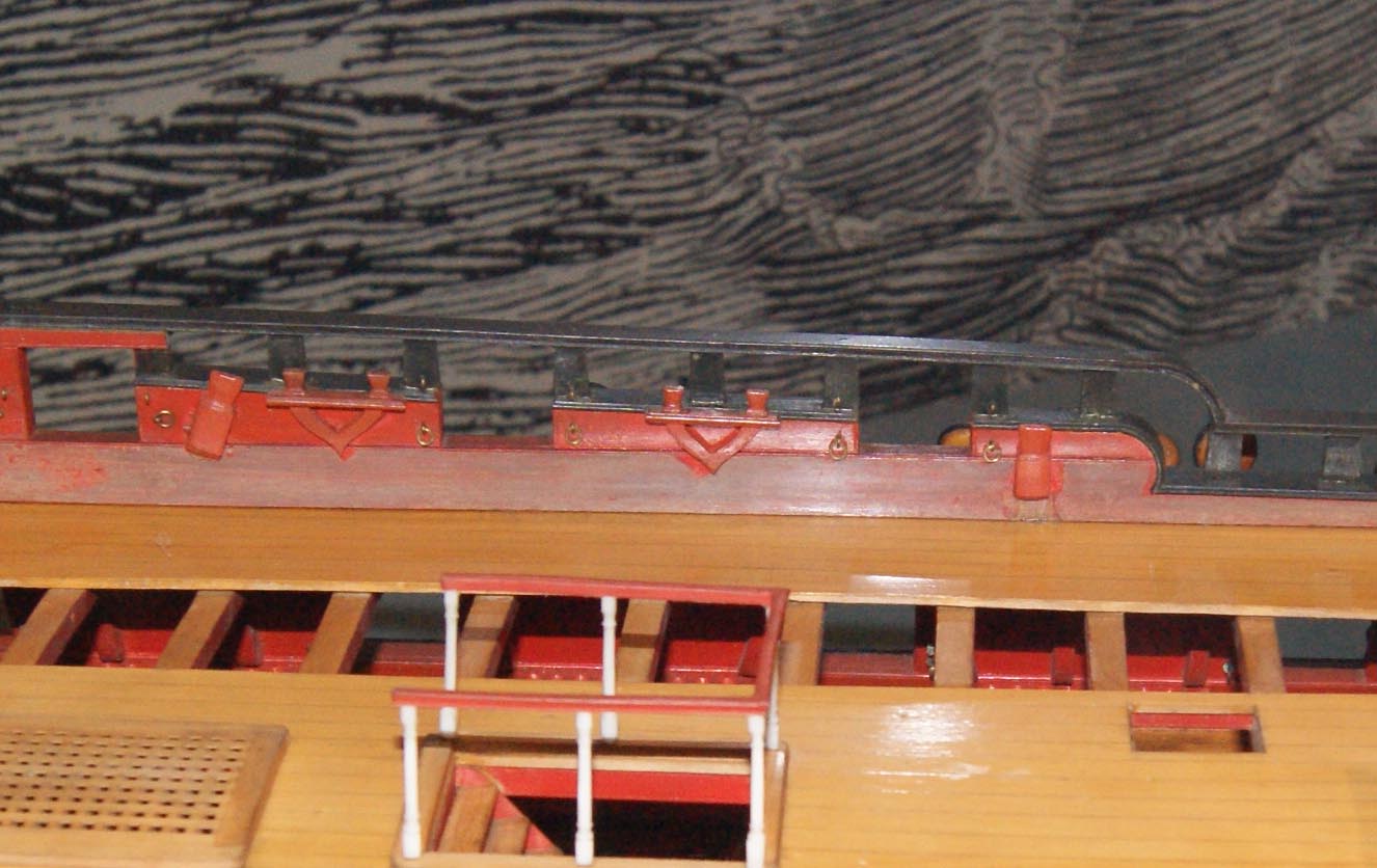
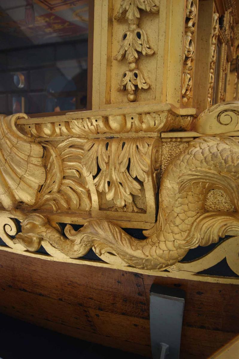
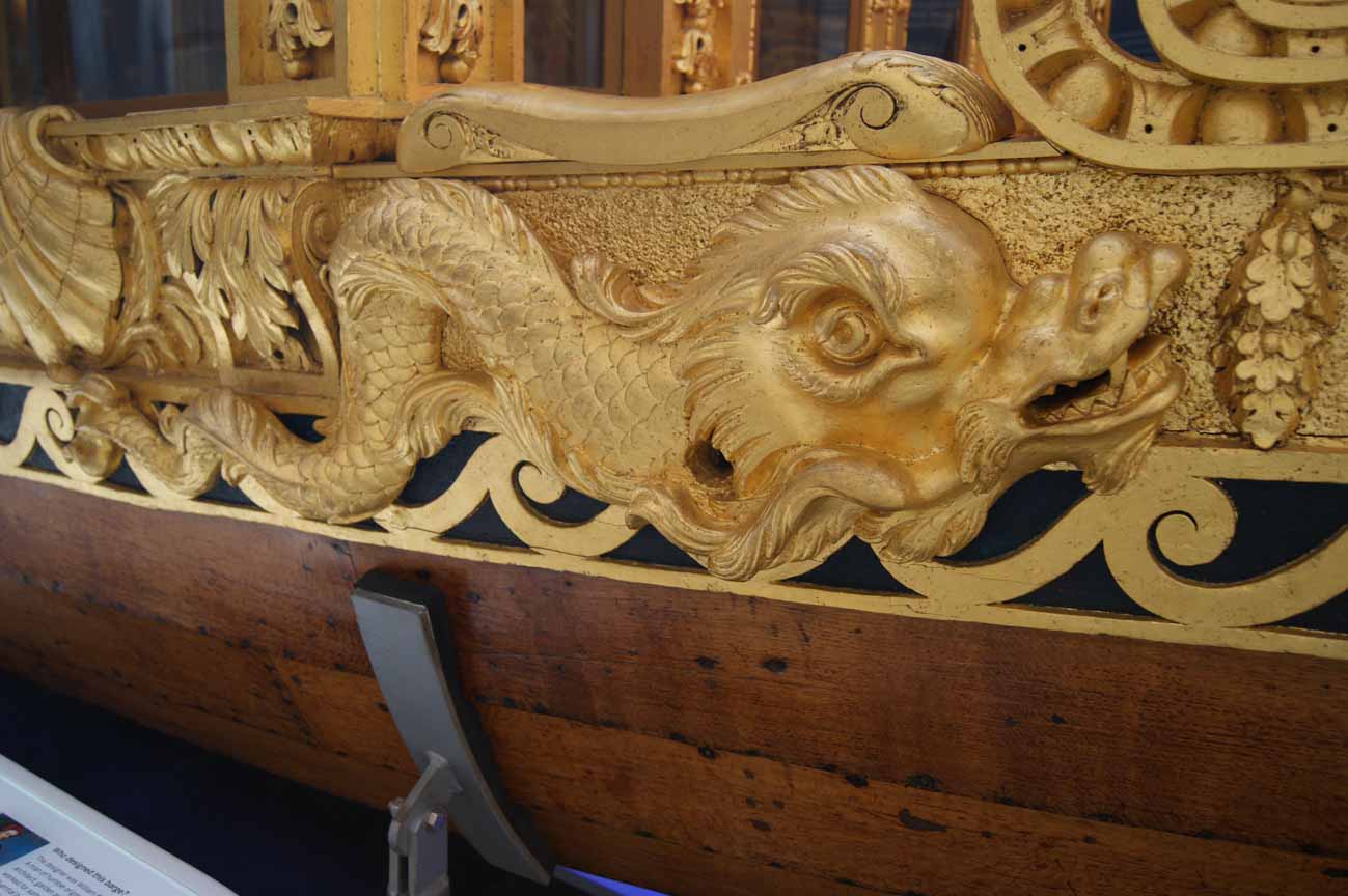
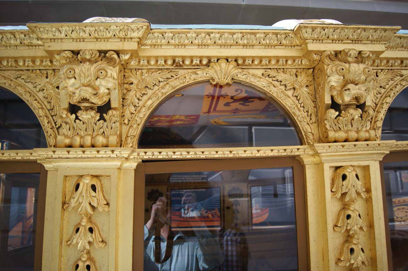
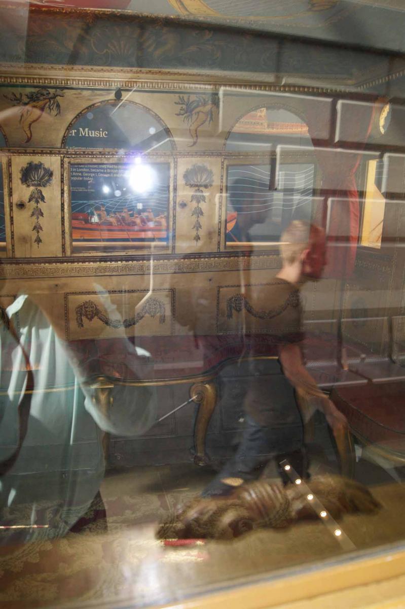
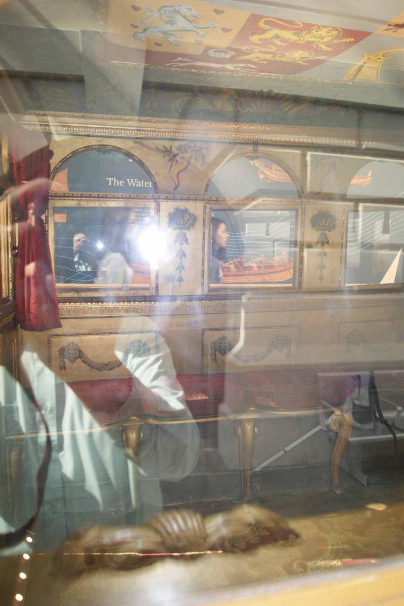
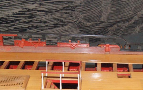
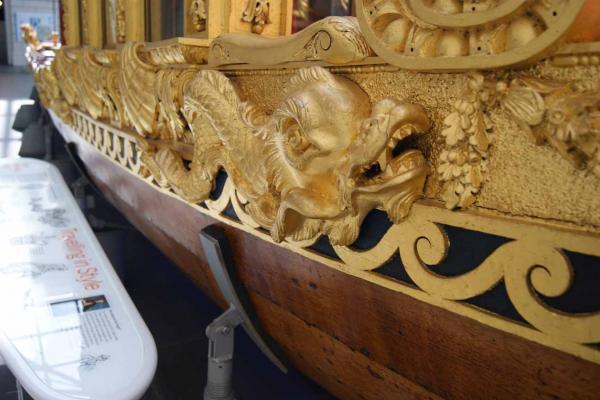
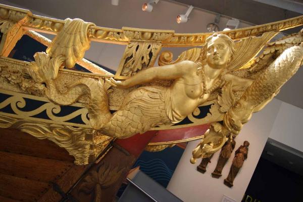
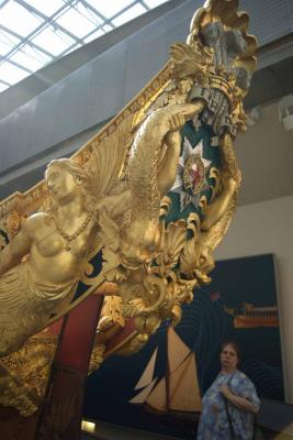
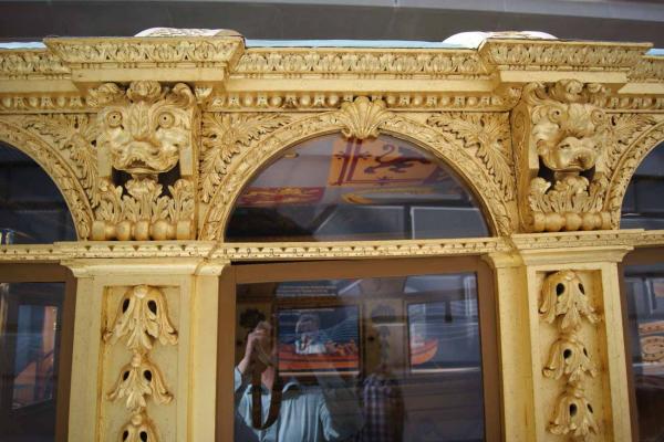
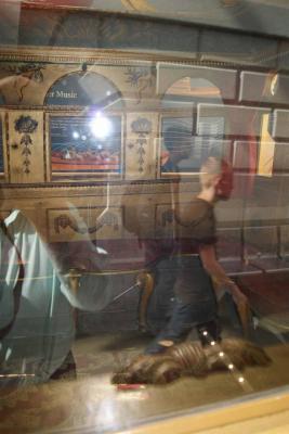
Greetings Druxey; I have some photos of the stern, with mermaids holding dolphins, and other carving details, but unfortunately none of the rowing benches. I do remember that they had the typical central plank joining all the thwarts, and parallel to the keel. However, I will be back at the NMM before too long, and I will take some more pictures for you. In the meantime, I am posting those I have already taken. For anyone else interested in the details of the carving, I will also post these on the contemporary models gallery. All the best, Mark P The first two (they were last when I uploaded them!) are of the interior of the cabin, and taken through the glass. It takes a few moments to realise what is inside the glass, and what is a reflection.


- 641 replies
-
- 19
-
-
- greenwich hospital
- barge
- (and 1 more)
-
Greetings Druxey; A clear explanation and a very useful tip. Many thanks for showing us. The photographs are a great help also. This will be a very interesting model to follow. It always seemed a miracle to me that these unseaworthy-looking vessels managed to stay afloat even in the relative calm of a river. They are lovely to look at, though. Following on from Siggi's post above, I have some close up shots of the carving on Prince Frederick's barge in the NMM, which I have been intending to post on the contemporary models gallery. Some of these show the interior, although I had to take them through the glass, so they are somewhat obscured. I can post them here as well, if you wish, or send them by PM or other method. All the best, Mark P
- 641 replies
-
- 4
-
-
- greenwich hospital
- barge
- (and 1 more)
-
where can find this Awesome model ??
Mark P replied to mahmoud sabra's topic in Wood ship model kits
Greetings everyone; I am not sure which vessel it is, but it is certainly not a model of an English warship. The deeply curved head rails, the 'rose' type carving where they meet the forecastle, and the gun-port wreaths, all match with pictures I have seen of 'Soleil Royal' so that would seem to be a good suggestion, as Jan mentioned above. All the best, Mark P -
Greetings everyone; I just thought that my experience with obtaining boxwood may be of interest to some other members. I live in the countryside, and I have mentioned to friends and acquaintances that I am interested in obtaining supplies of boxwood. This paid off for me in Autumn 2014, when one of them told me that he knew a gardener on a large country estate, who was felling a couple of box trees and had offered to let me have the wood (even better, FOC, though I gave him something) Naturally, I bit his hand off, and carted them off home. I had to band-saw them down and then put the planks into sticks to season, but it was well worth the time and effort. However, this set me to thinking, and I contacted a very large country estate not too far away, and soon discovered that they had a whole plantation of box trees, and I could take some away at the cost of about £33 per 100kg! (220lbs for our friends over the Pond) All I had to do was mark the trees, and they would fell them for me to collect (I can tell you one thing, fresh-felled boxwood is incredibly heavy for its size) Soon there were more planks in sticks, drying out. Then today, another contact, a gardener on another country estate, called me, and said that he had just felled a box tree, and would I like to take the logs away. Needless to say, these are now in my shed awaiting ripping down. So I now have a good supply of boxwood seasoning, and although none of the planks are lumber sized, and many are quite small, I anticipate a use for most. Another plus is that I can take advantage of curved logs (and boxwood has many of them!) to band-saw them up in a way that gives me compass timber, which will be very useful. So if anyone is looking for boxwood, try spreading the word, or contacting some nearby estates, and you may be successful. Happy modelling! Mark P
- 70 replies
-
- 12
-
-
what is the ship at the backdrop of the forum?
Mark P replied to Eibwen's topic in Nautical/Naval History
Sorry gentlemen, it's definitely not Tremendous. I have the as-built draught of her for my current project, with the name written on her counter. However, I chose her after considering many others, one of which was HMS Cumberland, which is what the draught in the background is of. The stern view of Cumberland also shows the name, so there cannot be any doubt. All the best, Mark P -
Hi grsjax; This certainly seems to be an interesting new development. Many thanks for bringing it to this site. All the best, Mark P
- 1 reply
-
- 1
-
-
Congratulations Tarjack; This is an inspirational project, beautifully carried out, in an unusual material. Your story of the police coming to visit is great; at least they didn't dig up the patio! I will follow your build with great interest. All the best, Mark P
- 241 replies
-
- 4
-
-
- royal caroline
- yacht
- (and 1 more)
-
What is the name for the netting under the bowsprit
Mark P replied to HKC's topic in Masting, rigging and sails
Hi HKC; I'm with jb on this. When these nettings first appeared, they were rigged above the bowsprit, and their purpose was to hold the staysails when lowered. It was only later that they were rigged below the bowsprit, to catch those who lost their footing while working on the headsails. All the best, Mark P