Mark Pearse
-
Posts
836 -
Joined
-
Last visited
Content Type
Profiles
Forums
Gallery
Events
Everything posted by Mark Pearse
-
 Hi Michael I'm not sure about butting in, but hopefully this is helpful, & apologies if it isn't. The bow is certainly very fine. Personally I doubt the builders would have thinned the planks at the bow, I reckon they would just use a wider stem timber & placed the rabbet line to suit. I reckon the steps are: they decided a minimum remaining timber thickness after the rabbets were cut into the stem timber; if the two plank thicknesses plus this minimum thickness totals 2.5", then the rabbet line at the bow will follow the 2.5" hull thickness line, like a contour on a survey plan. So the fine lines don't need to be made more chunky, but it would mean a wide outer stem to achieve the fine bow - but it would be strong & the width of the outer stem would look elegant & emphasise the fine lines.
 -
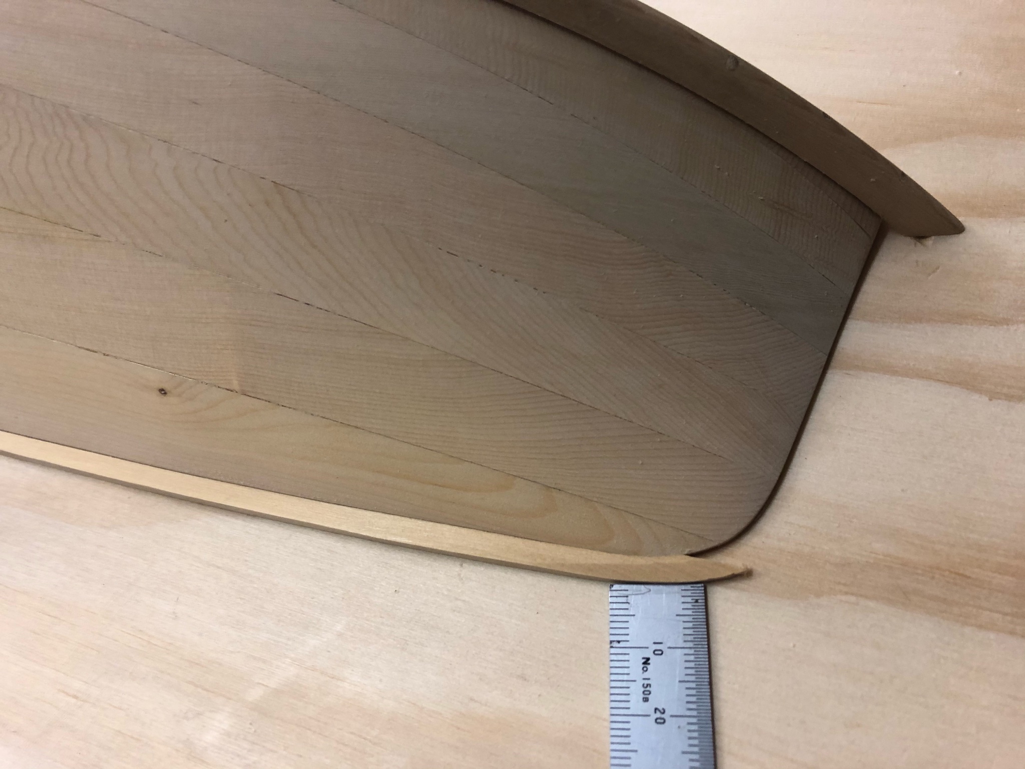
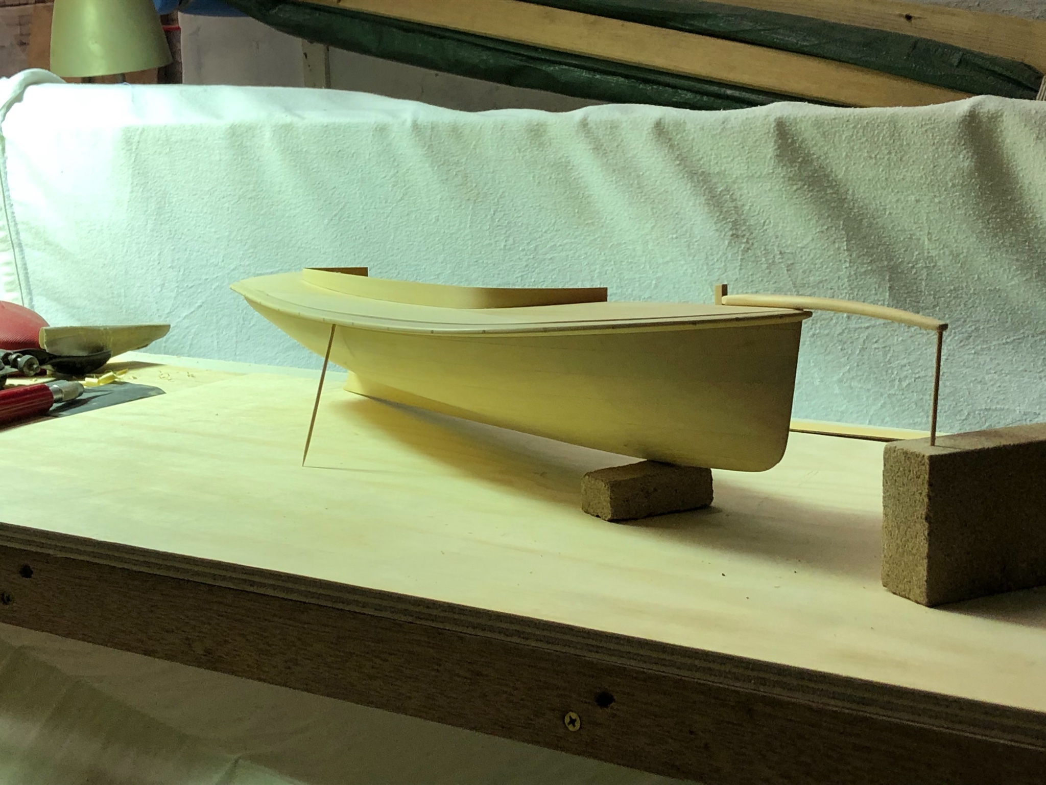
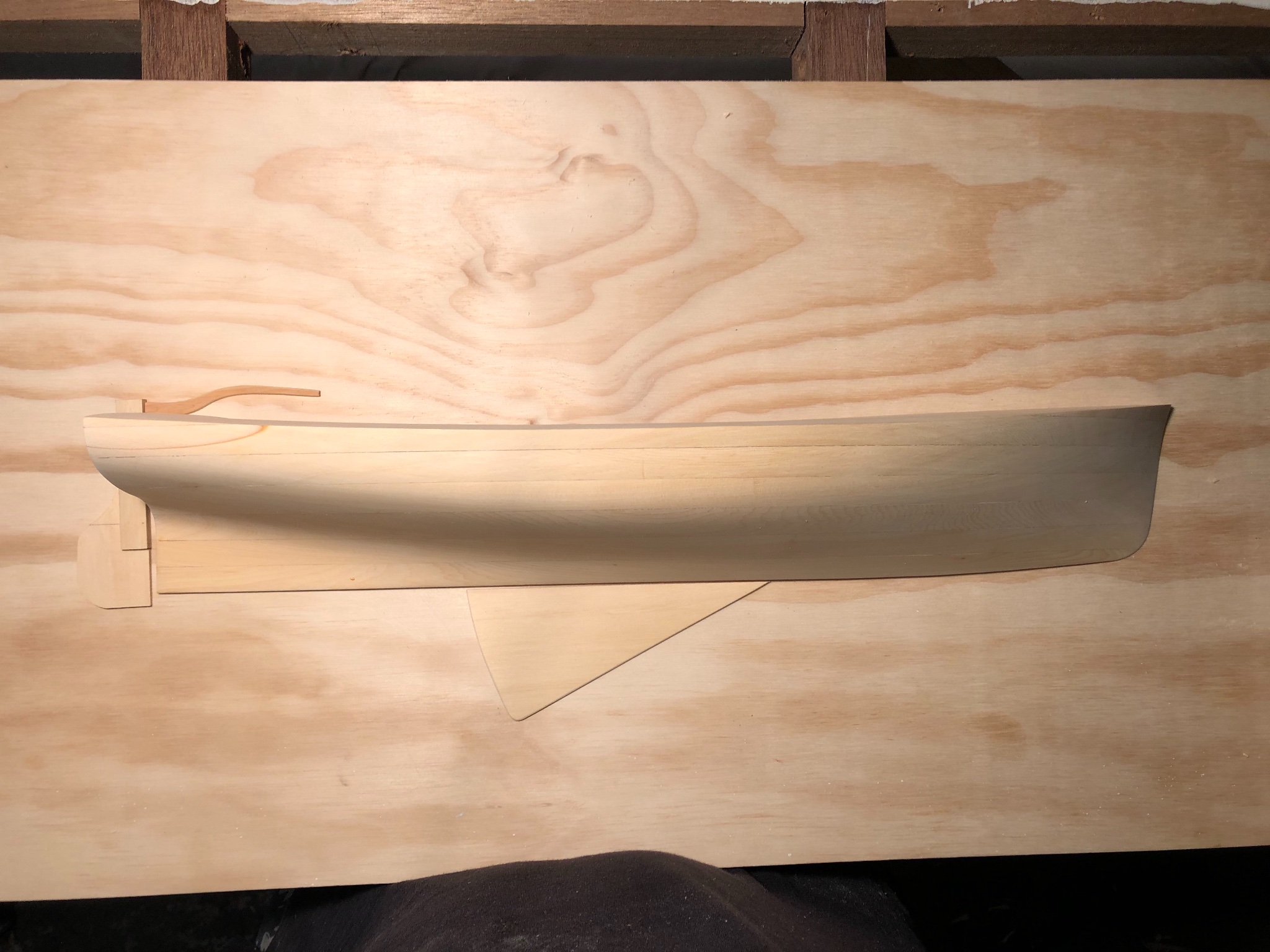
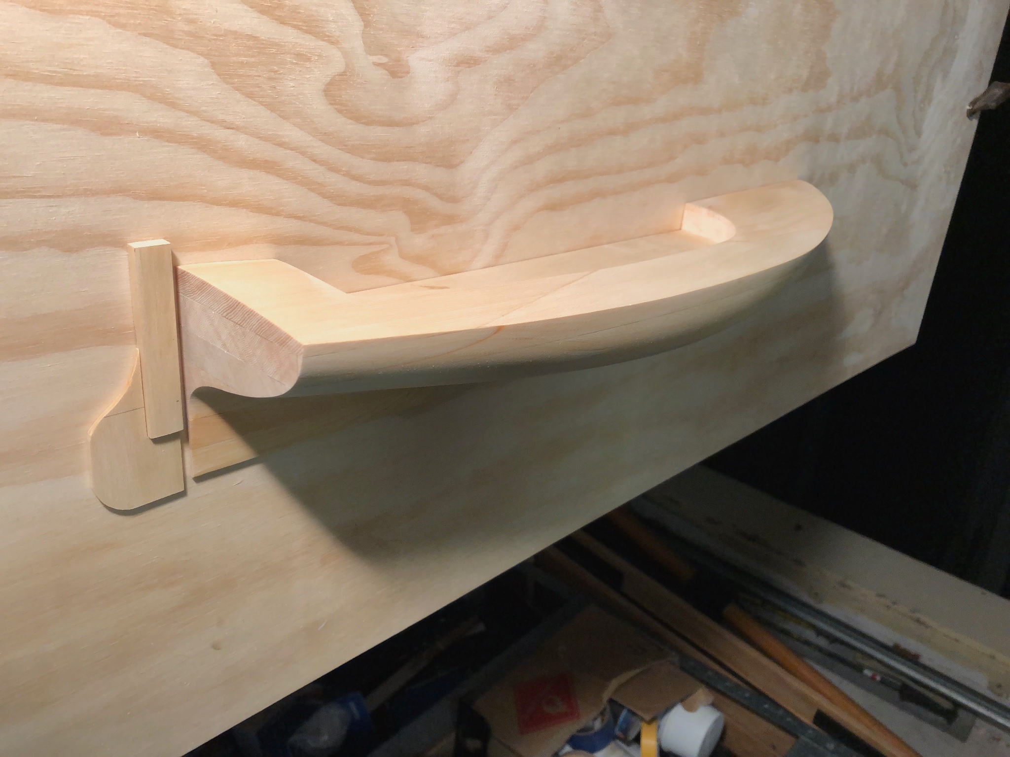
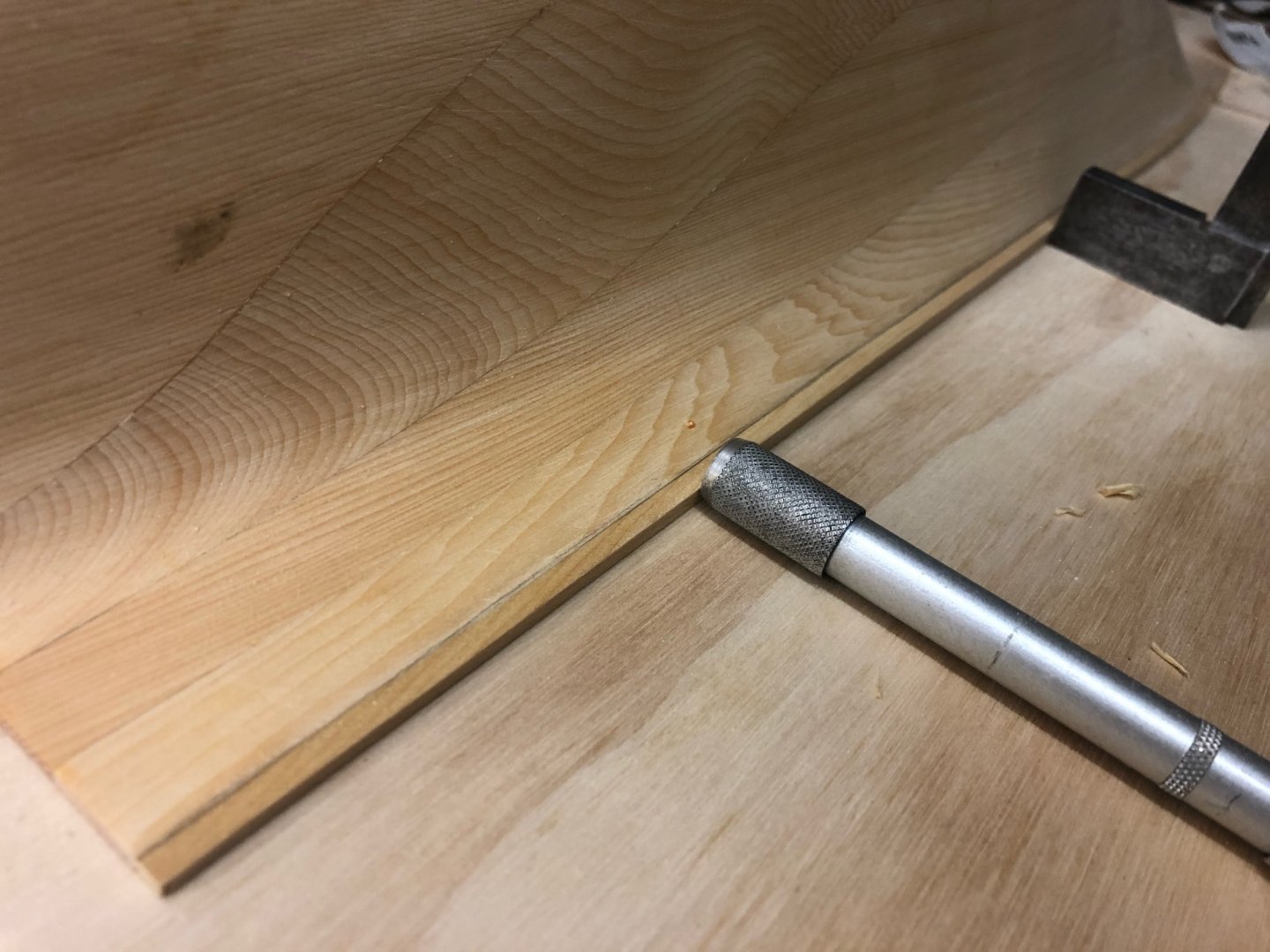
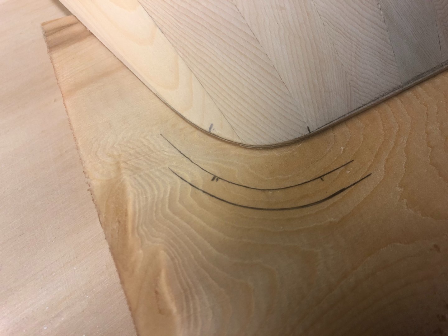
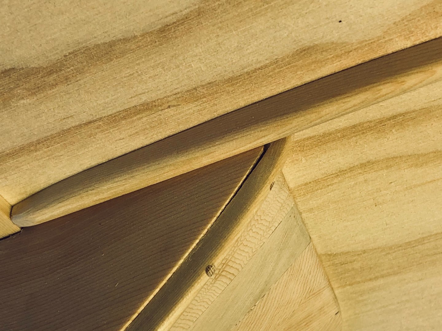
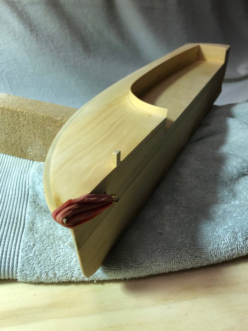
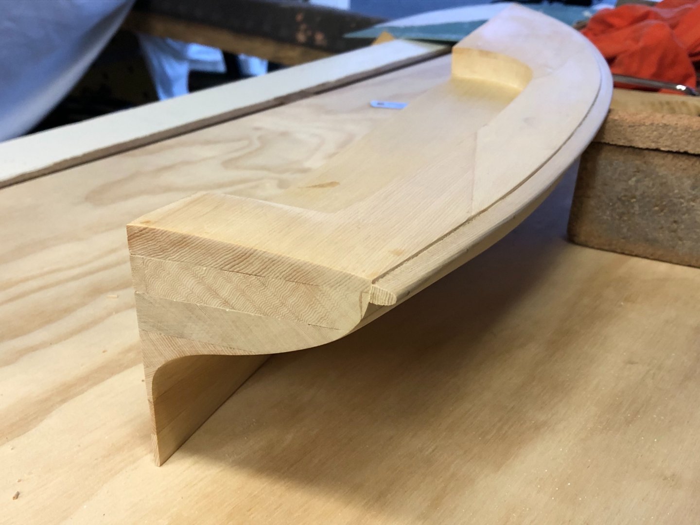
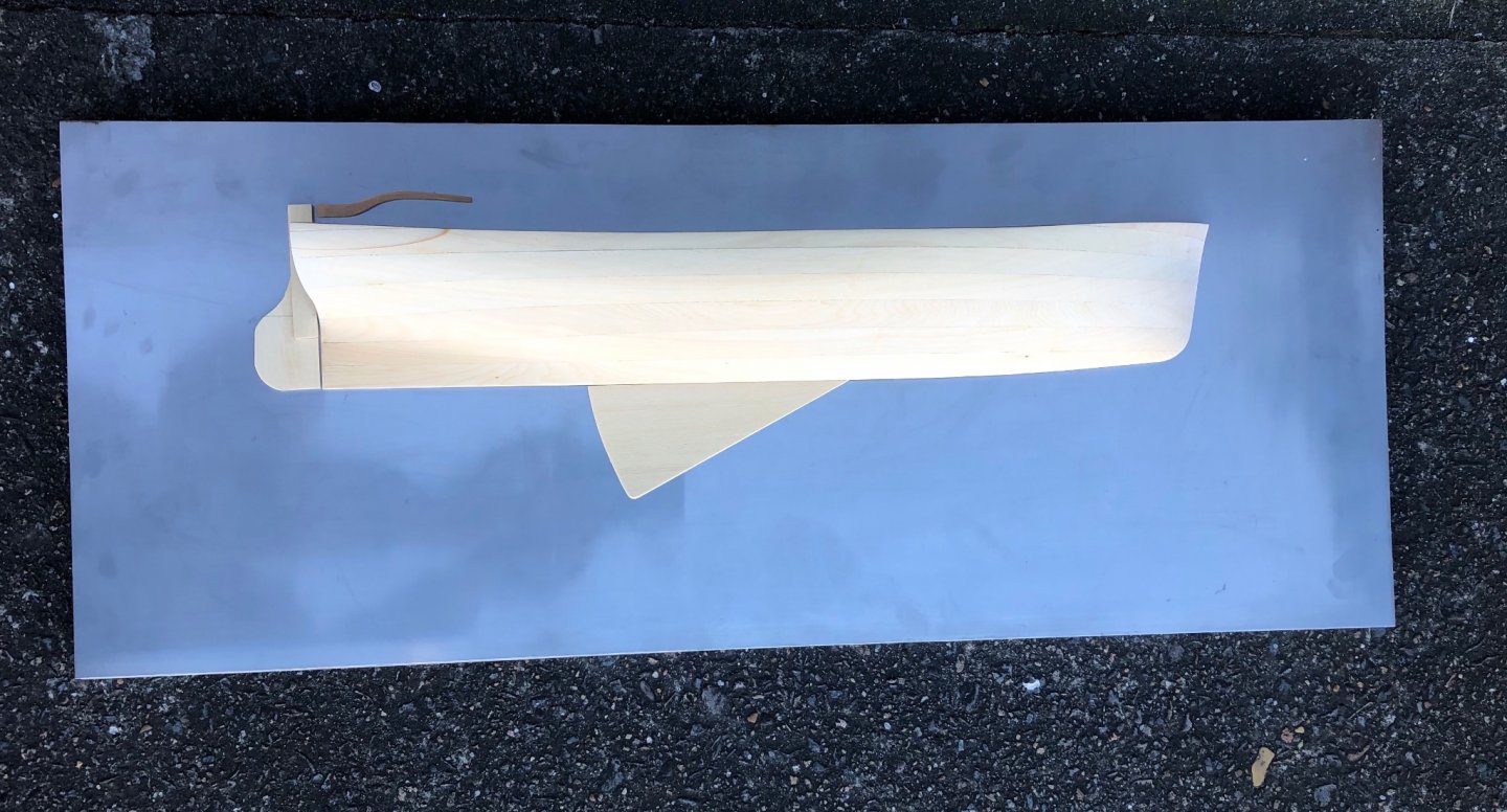
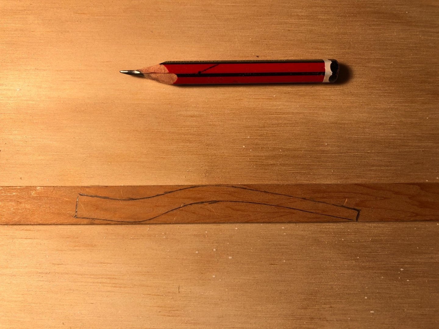
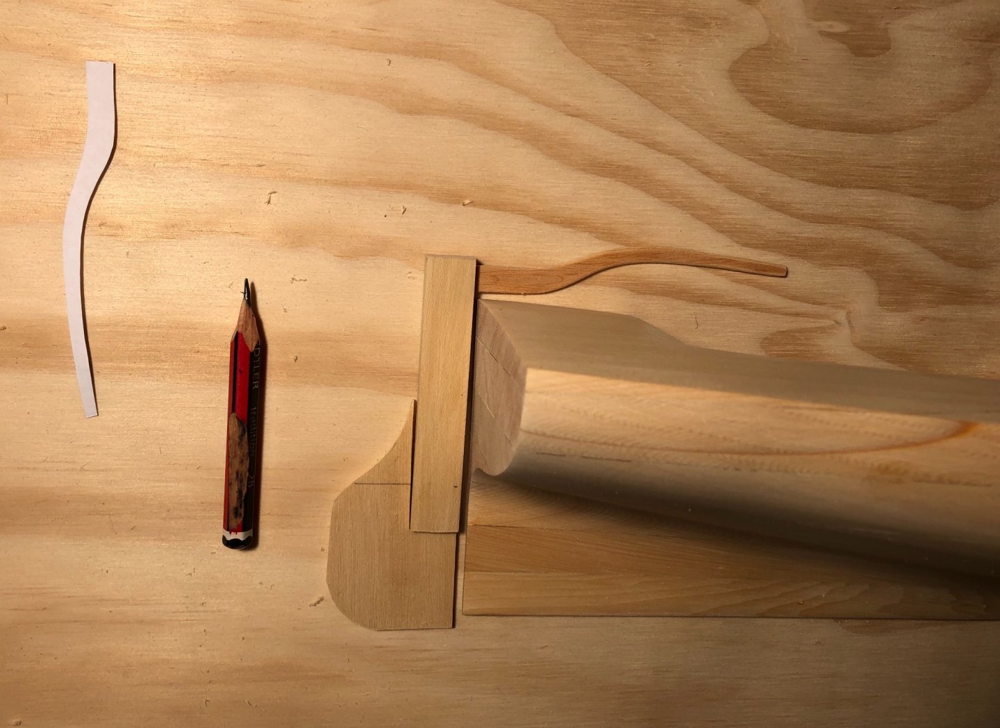
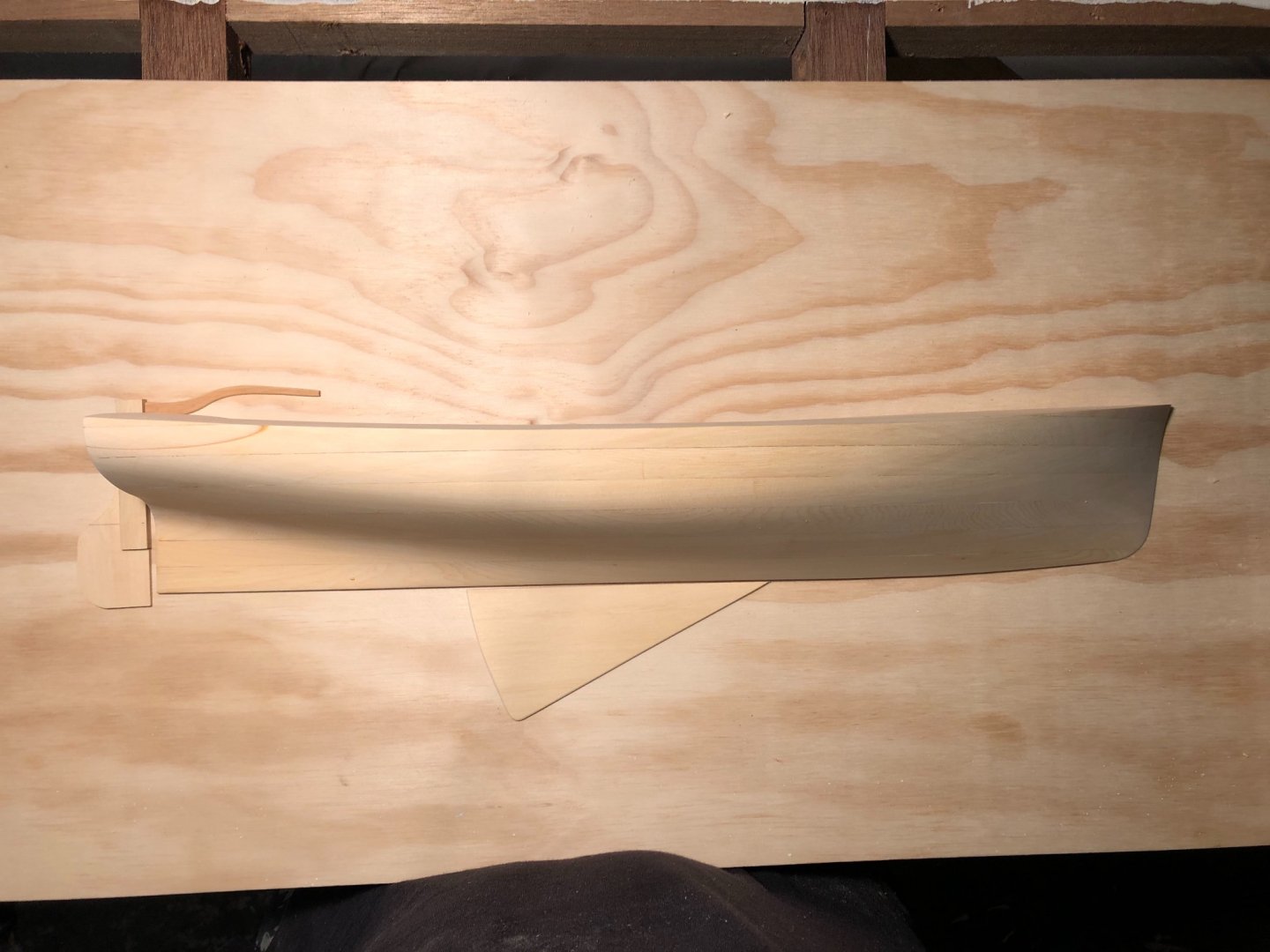
I'm working on the outer parts of the stem & keel. The lines drawing of the design appears to stop at the rabbet line, so I guessed the visible amount below the rabbet line at 45-50mm. This boat would have been lightly built. I'll glue the pieces on before doing final shaping where it meets the bow lines. I don't have a pic of the stem piece, but the curved part (name?) is below. I chose a part of the timber near a knot, that suits the shape. The bowsprit is roughly shaped, & it still looks a bit thick to my eye. The forward part of the gunwale is lifting, I've bound it with rubber bands & tried some epoxy. The hull is looking good. The virtue of adding the gunwales & other details in showing; compared to photos without these details the sweet lines are more visible. And the coaming is glued in - I managed to domesticate the Makita table saw enough to get a 1mm slice, & with the heat gun it bent easily. The bowsprit is definitely too heavy looking, & the coaming needs to be trimmed parallel to the deck line.


- 99 replies
-
- 10
-

-
Hi Keith I think your metalwork is getting even better, this batch is beautifully delicate. PS I know them as whisker stays.
-
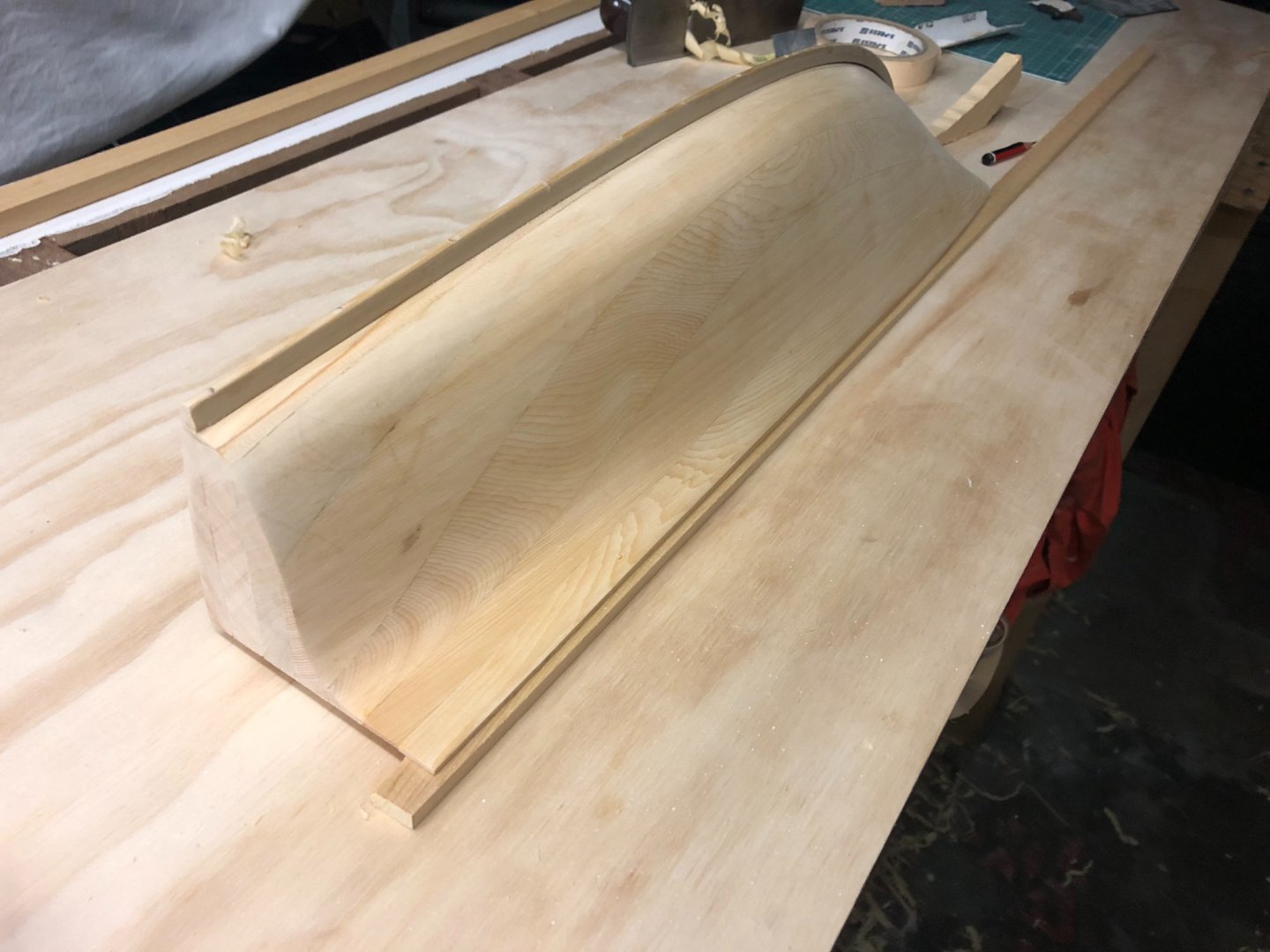
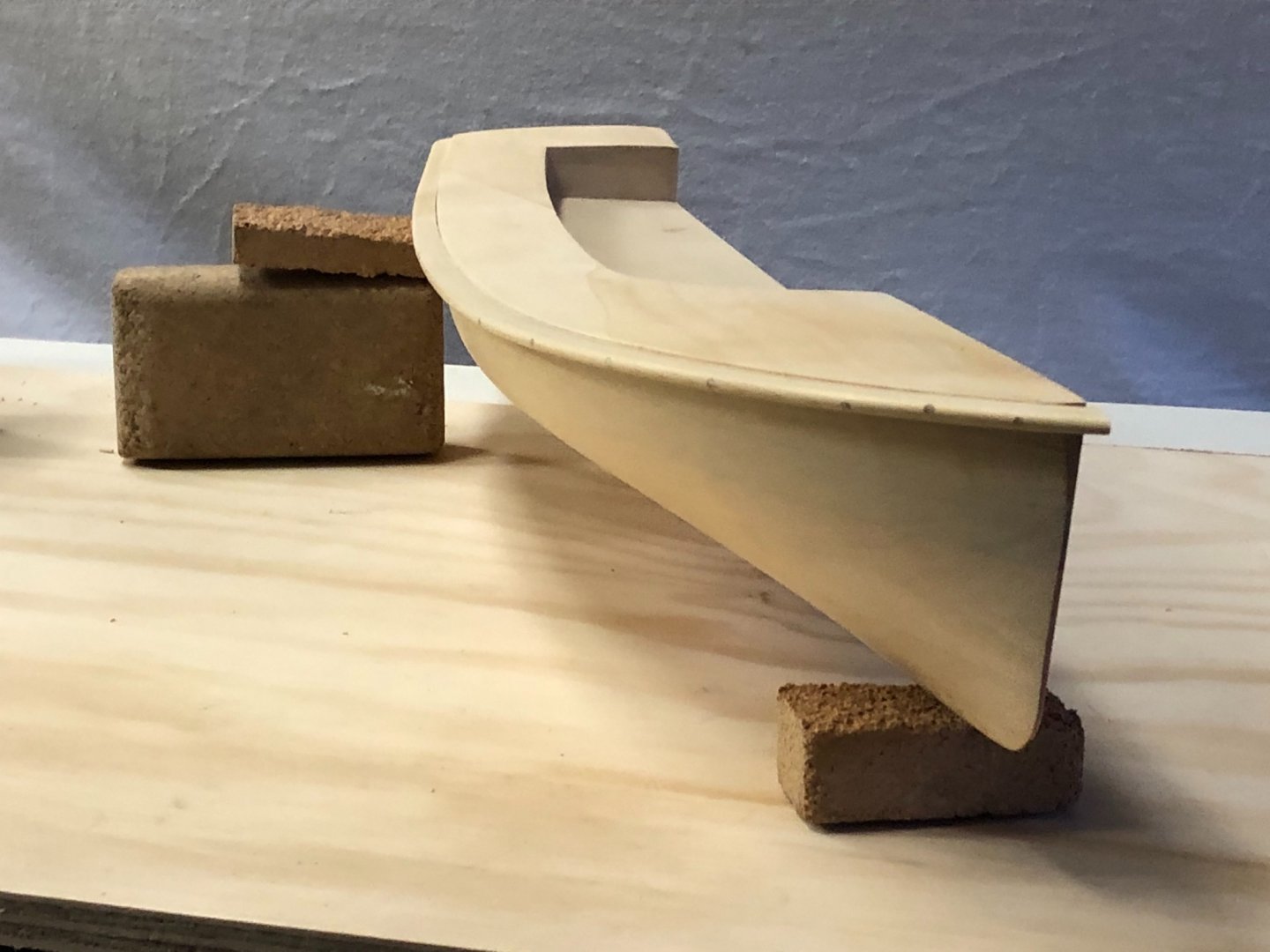
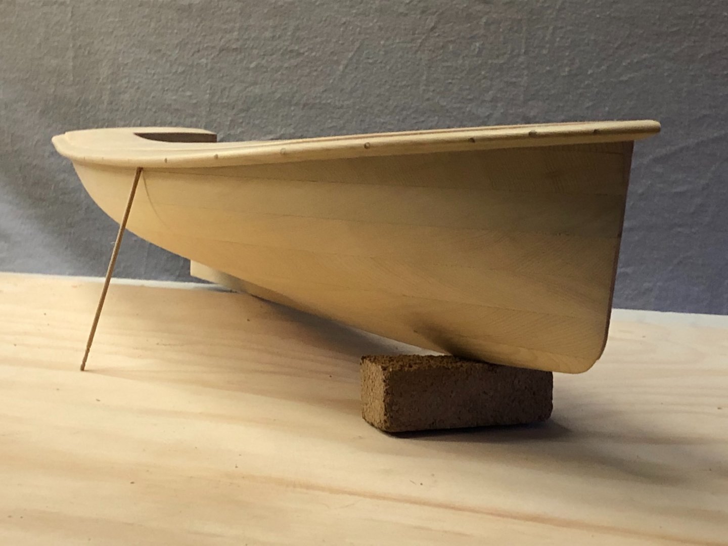
I made & attached the gunwale, first cutting a strip of Huon Pine: The shaping & bending it. Initially I used a heat gun to bend it, but although it was happy to curve that much it didn't want to stay there. Plus, because it was being bent against the wider dimension the timber wanted to twist away. So I used boiling water & clamped it for 24 hours, after which it still wanted to spring quite a lot. So the initial plan to just glue it was upgraded to plugs of timber (actually bamboo I think). The plugs stand out a bit, but I wondering about staining it, or maybe even painting the gunwale. Still just roughly sanded, but I love what adding a gunwale does for showing off the lines. She's really starting to show pedigree; & the fine entry & hollow exit lines are showing well. On an historical note, gunwales do seem to be larger & wider in the past. I carefully enlarged a stern photo of this boat & measured the size, & this is accurate, around 90mm wide actual.

- 99 replies
-
- 11
-
-
Hi Steve That looks very good. I like the delicacy of your design.
-
thank you everyone That is a big help. I'll experiment on a corner of the sheet soon & see how it goes.
-
Hi Shipman, thanks & sounds like a lovely motorbike. What compound, if any, did you use on the buffing wheel?
-
thank you Bob, I'll digest that before attempting anything
-
Jaager, Kurt, Roger - thank you for your thoughts. I'm not going to use glass because of that visual gap from the glass thickness when seen at acute angles, as Kurt noted. The front surface mirror is not something I've heard of & would bear investigation - except that am now the proud owner of a 1.6mm stainless steel sheet cut to size. Roger, I had wondered if something like this could work. Fortunately my brother has one of the rag wheels mounted to a heavy drill press. The polish acrylic mainly so I'd need to investigate the appropriate polishing bars, but probably a firm that sells them would advise. Any thoughts on the process below? Gently hand rub with some black scotch brite, then to white (maybe there's one between...), would get me close. Then perhaps the rag wheel trick. thanks
-
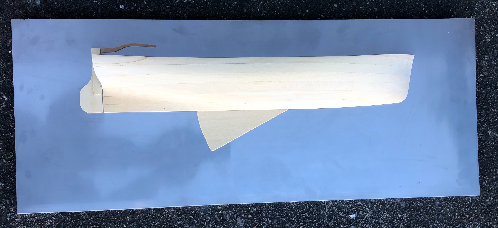
Hi everyone My current build is a half model & I plan to mount it on a sheet of mirror finish SS. I have a piece cut to size, it's 750 x 300mm, as per the poor quality photo below. The finish is some sort of mill finish, it's not brushed & it's smooth & relatively flawless but not polished. I want to polish to mirror finish, using straightforward tools like my hands, a drill etc. Has anyone any advice on a simple way to do this? thank you
-
well done, that is looking very nice
-
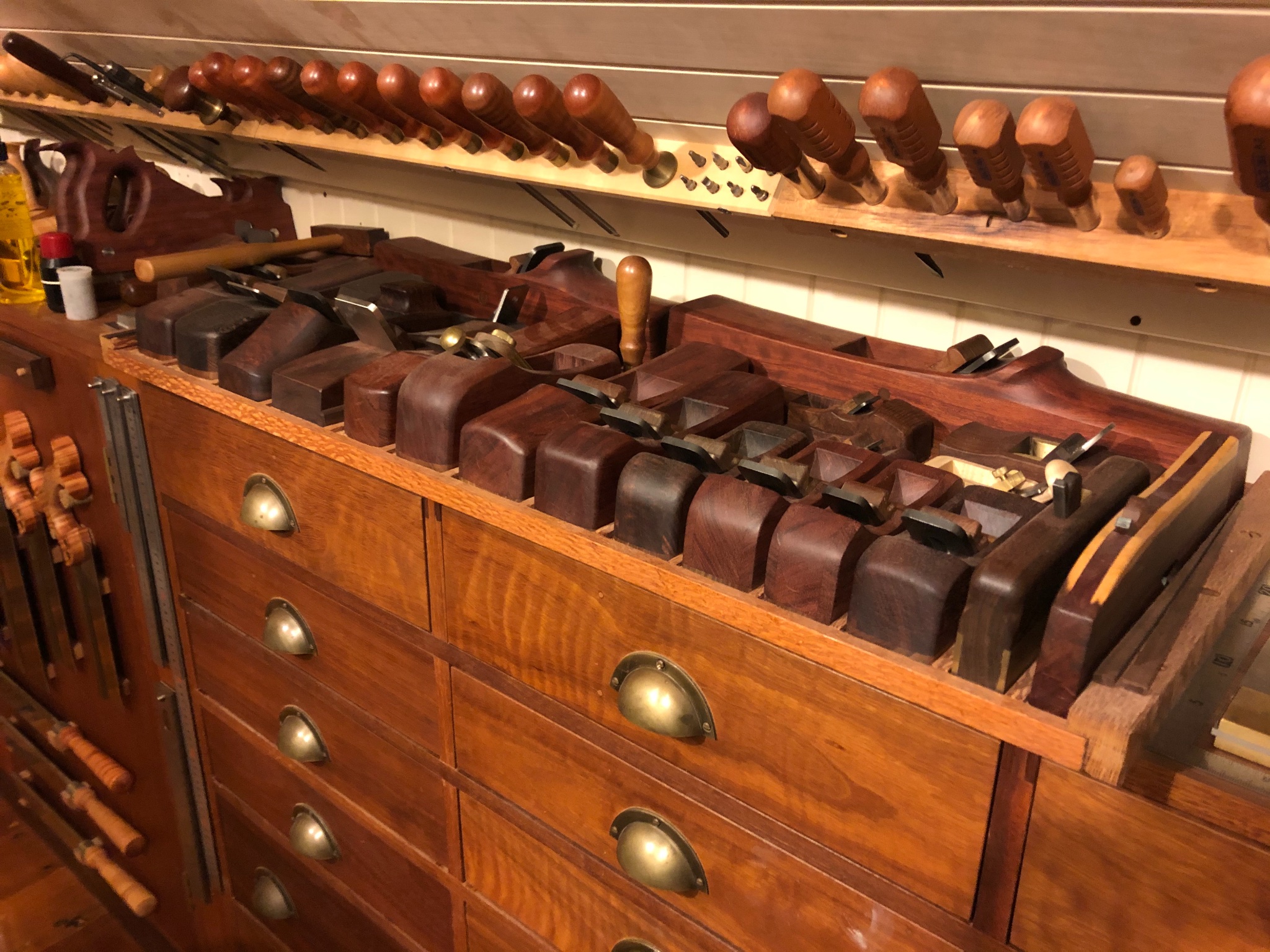
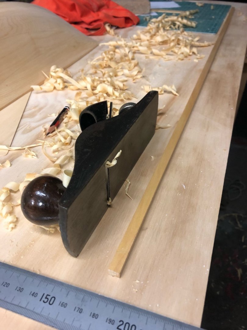
I have been reflecting a mirror surface for mounting the half model. Glass has issues in that the reflective surface is at the back of the glass & you would see that as a gap between the half model & its reflection. I thought about chrome or nickel plated brass, but in my experience there's some surface corrosion & it would need regular polishing to remove. I'd been investigating mirror finish stainless steel, even though the colour is a bit cool. Anyway, I managed to get an offcut at a good price. The SS sheet is 750 x 300mm, not yet polished. This poor photo gives an idea of the proportion. As an aside for those that love tools (which is probably everyone on this forum), the mate who I got the SS from makes acoustic guitars in his spare time. The pic below shows part of his workshop - the timber hand planes he made himself. I have never seen dovetail saws like these ones, they were a pleasure to hold.


-
Hi Druxey Just found this build. Such a lovely hull, I shall be following with interest.
- 433 replies
-
- 4
-
-
- open boat
- small boat
- (and 1 more)
-
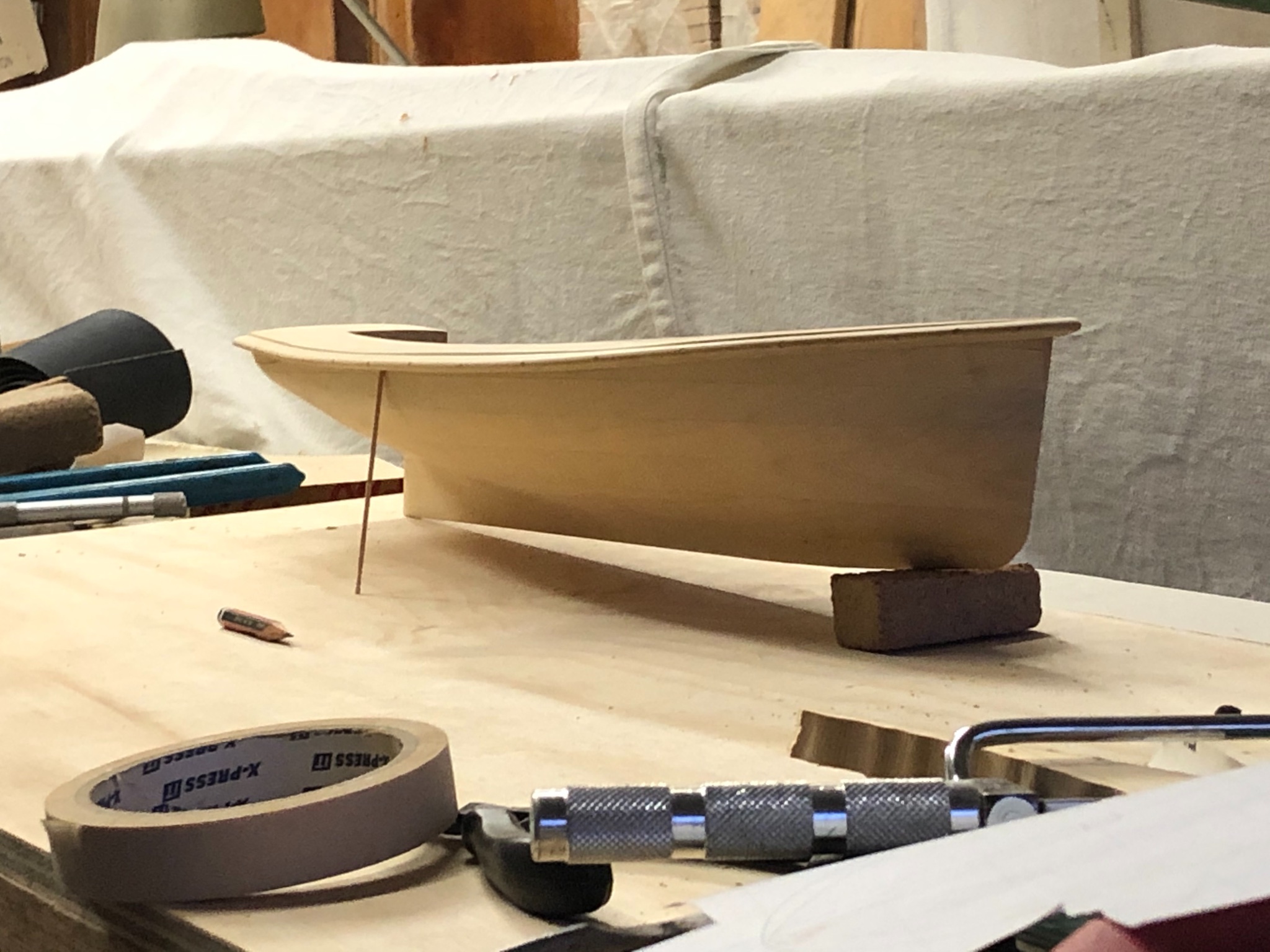
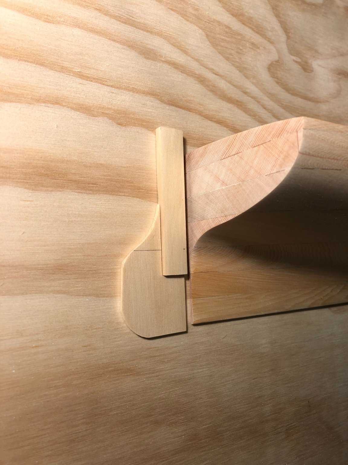
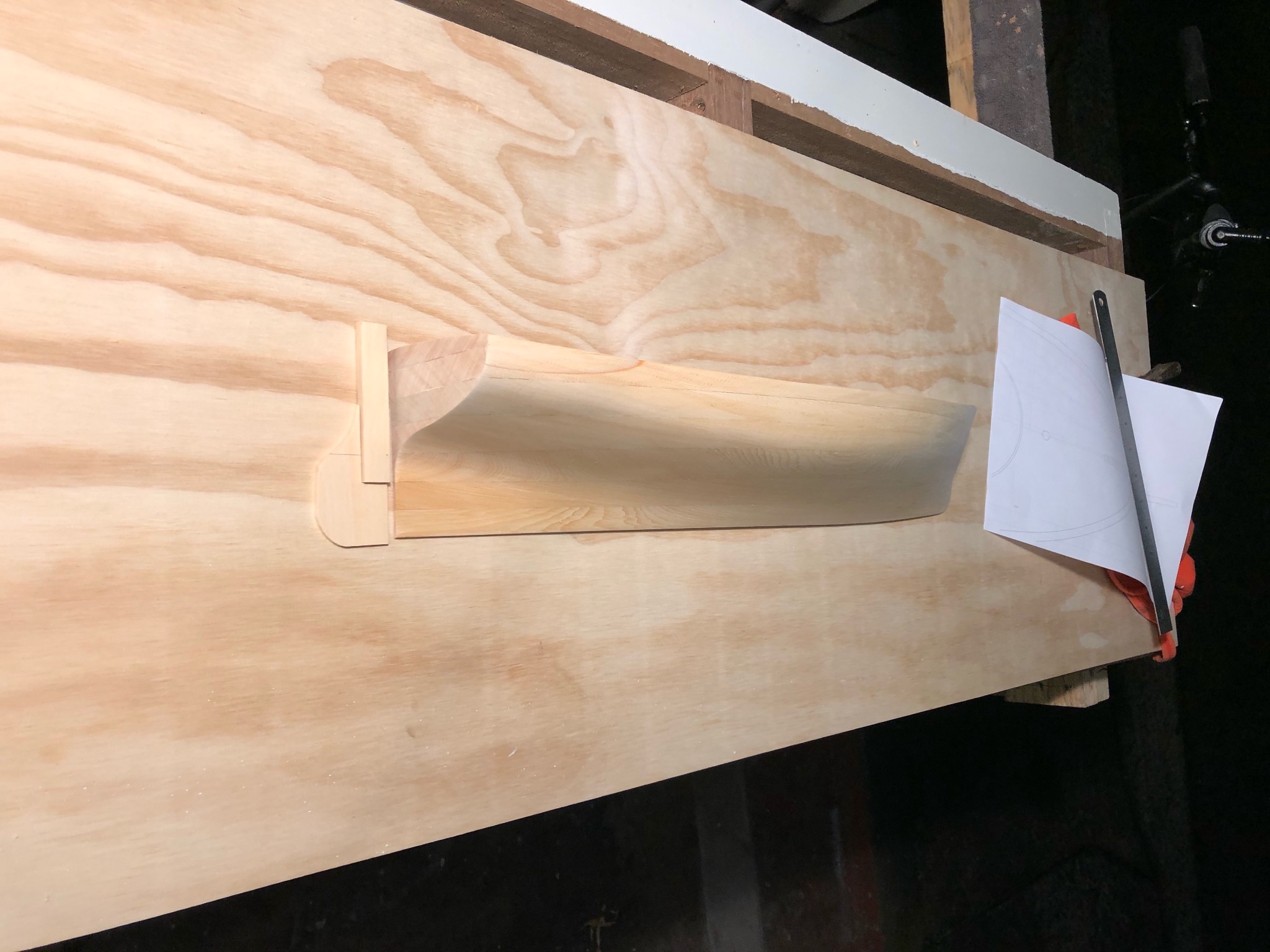
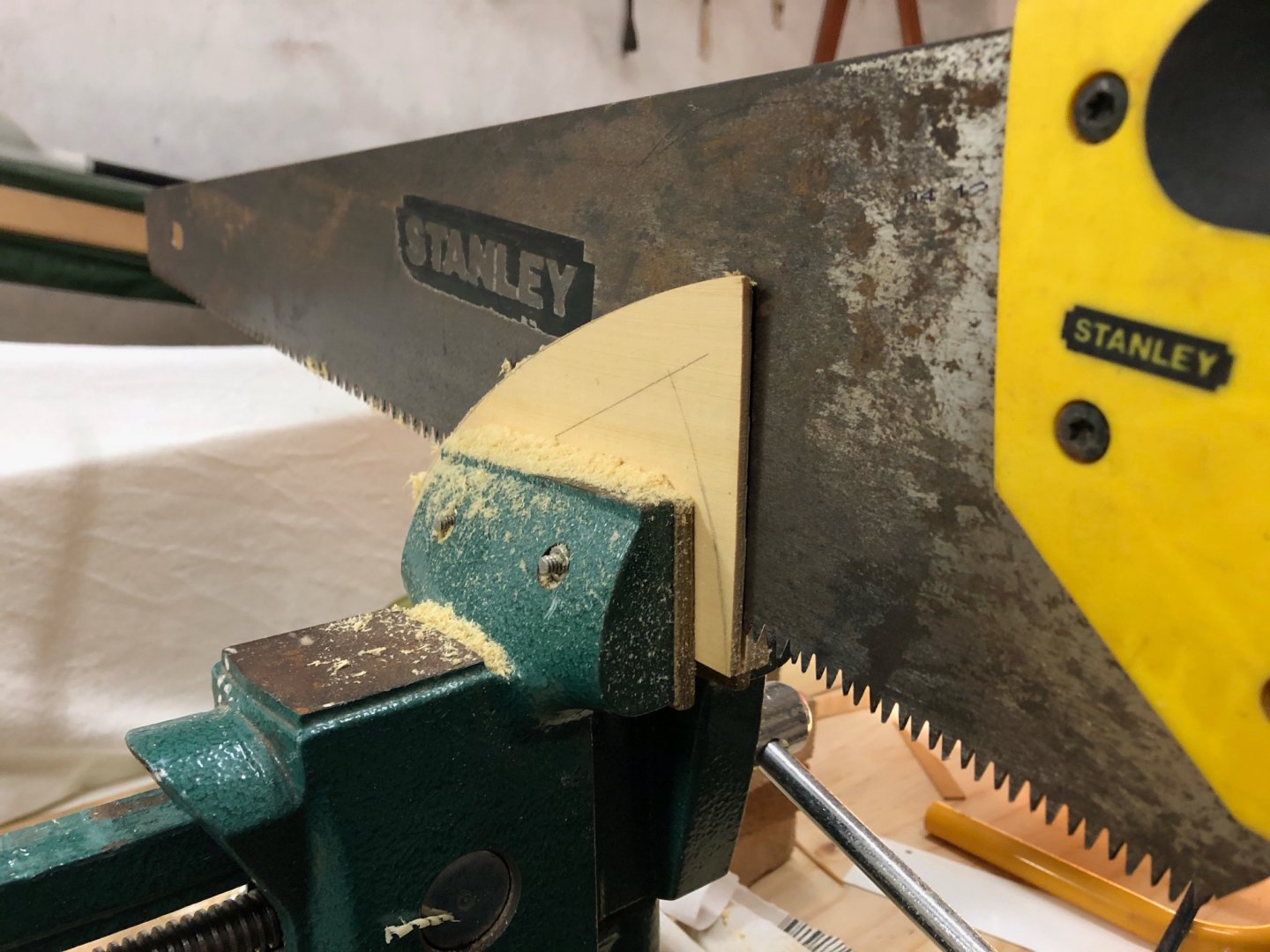
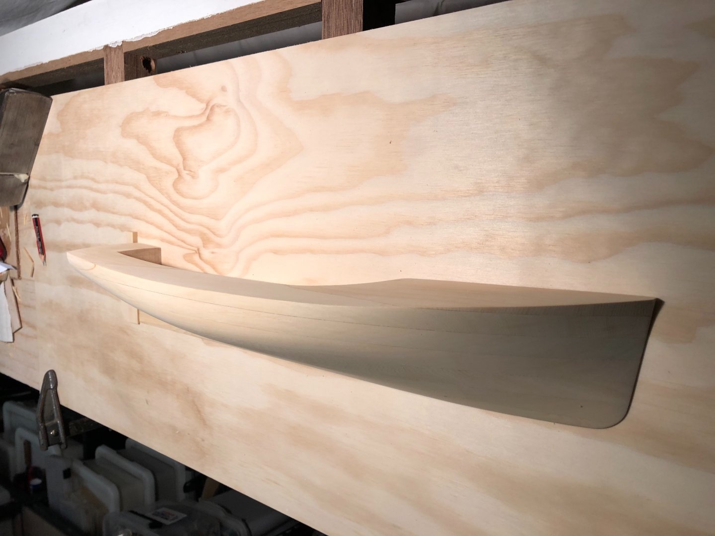
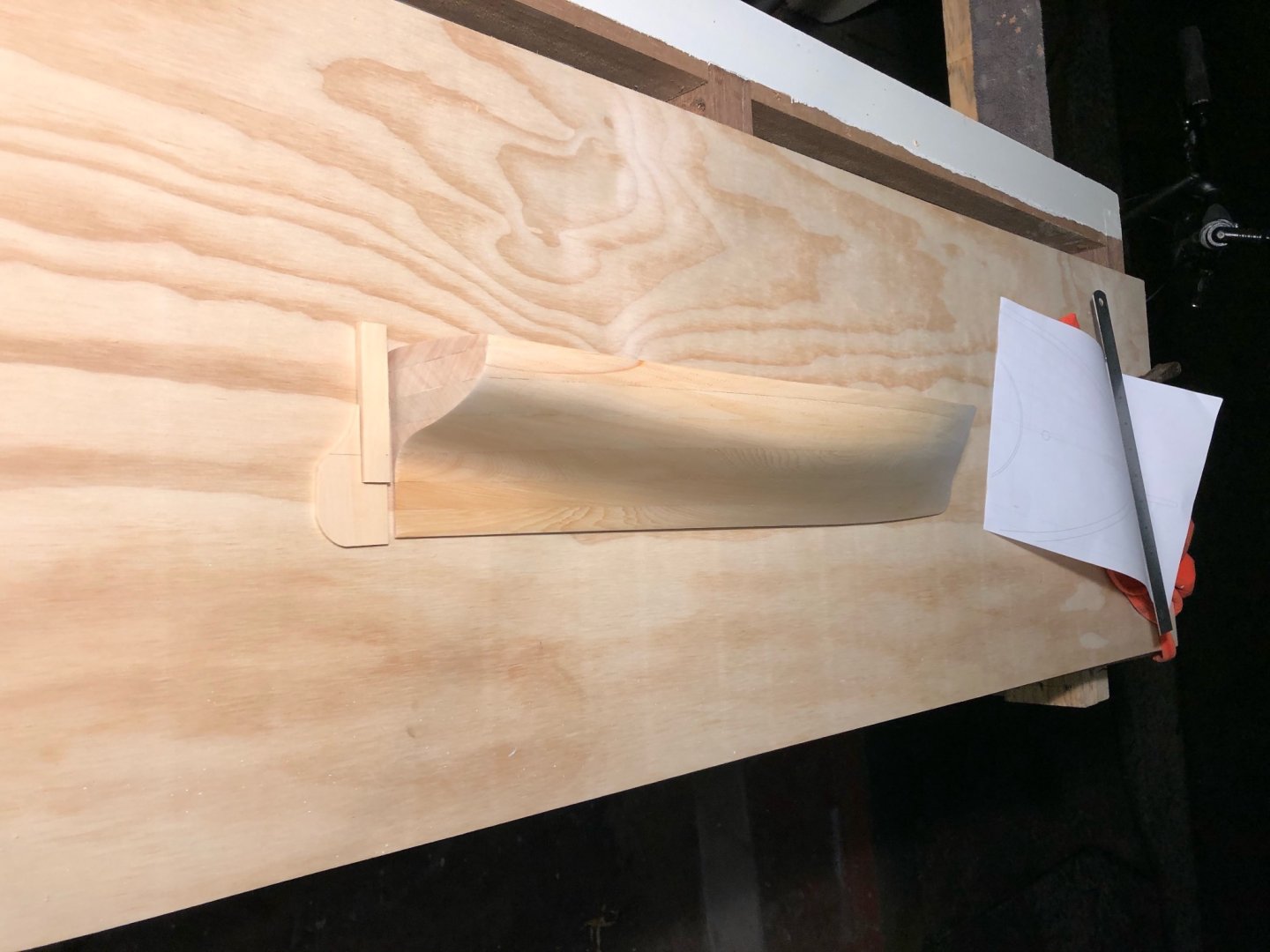
Thank you Steve, & welcome Pat. This one isn't one of the skiffs, although her shape is certainly influenced by them. More progress. Tiller arm roughed up & rough sanded. Next, the centreboard. Better get out the extra delicate thicknesser for this job... Sawn, planed, sanded, shaped & approximately in position. Looks little too far forward.
-
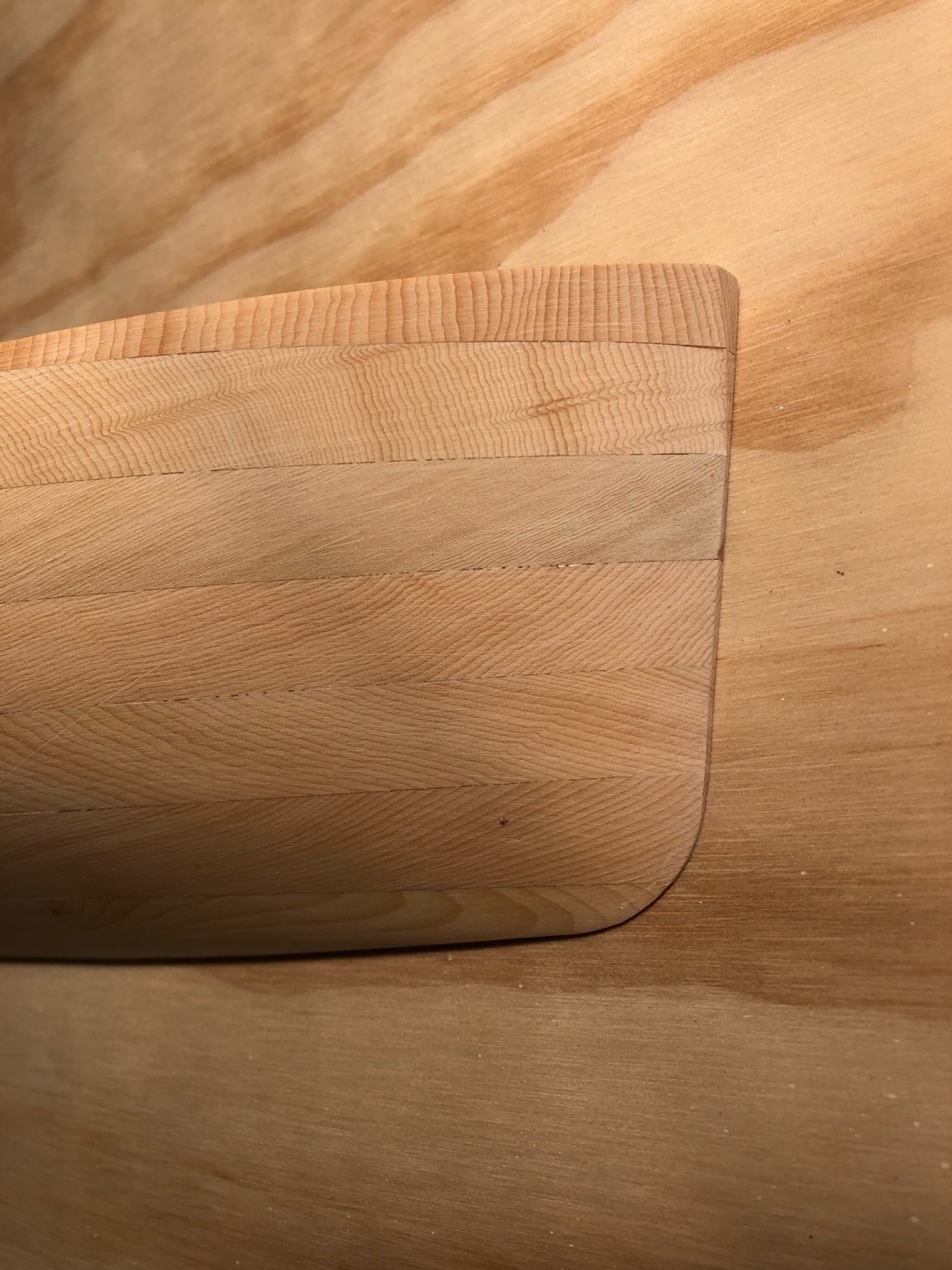
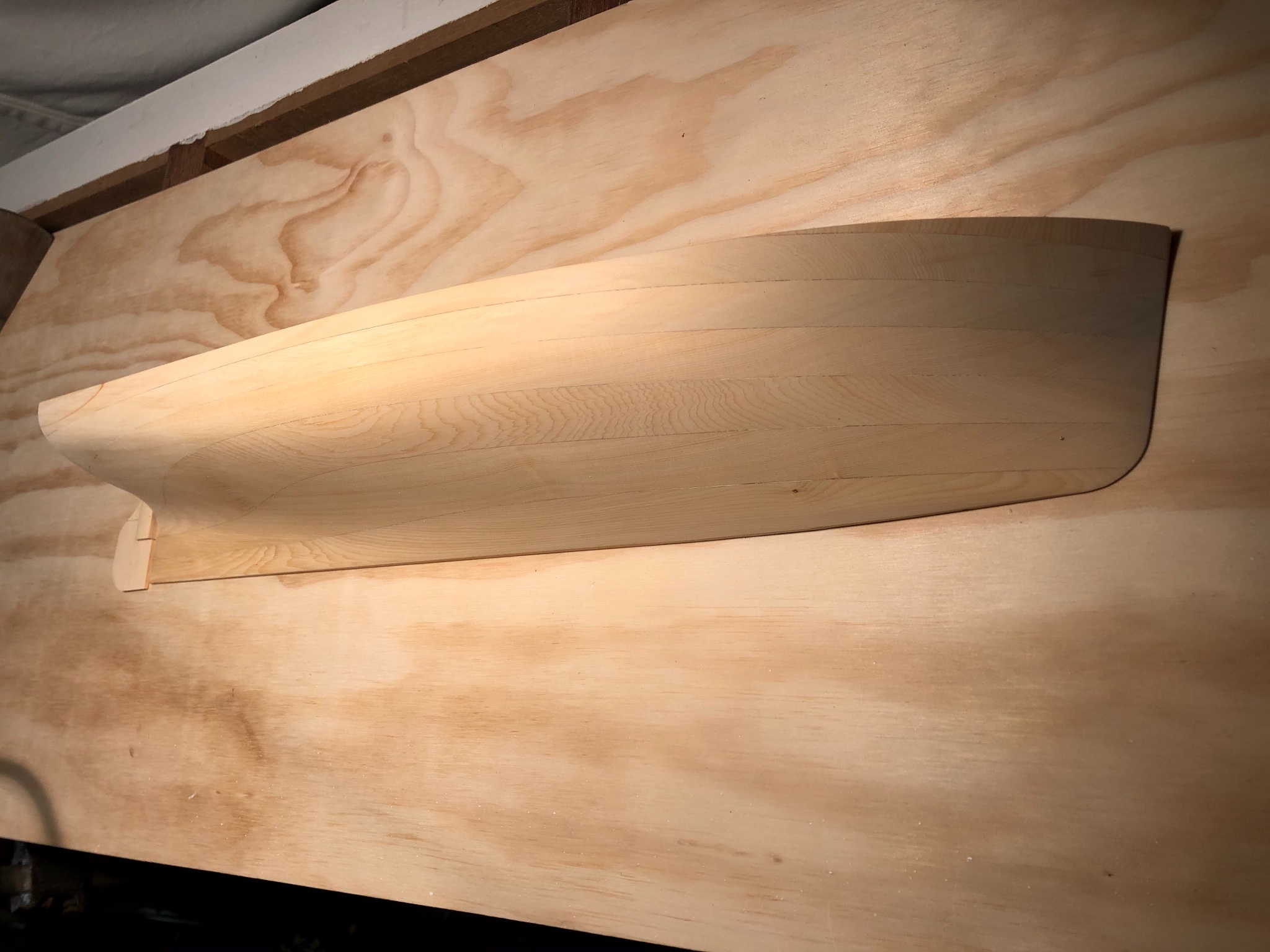
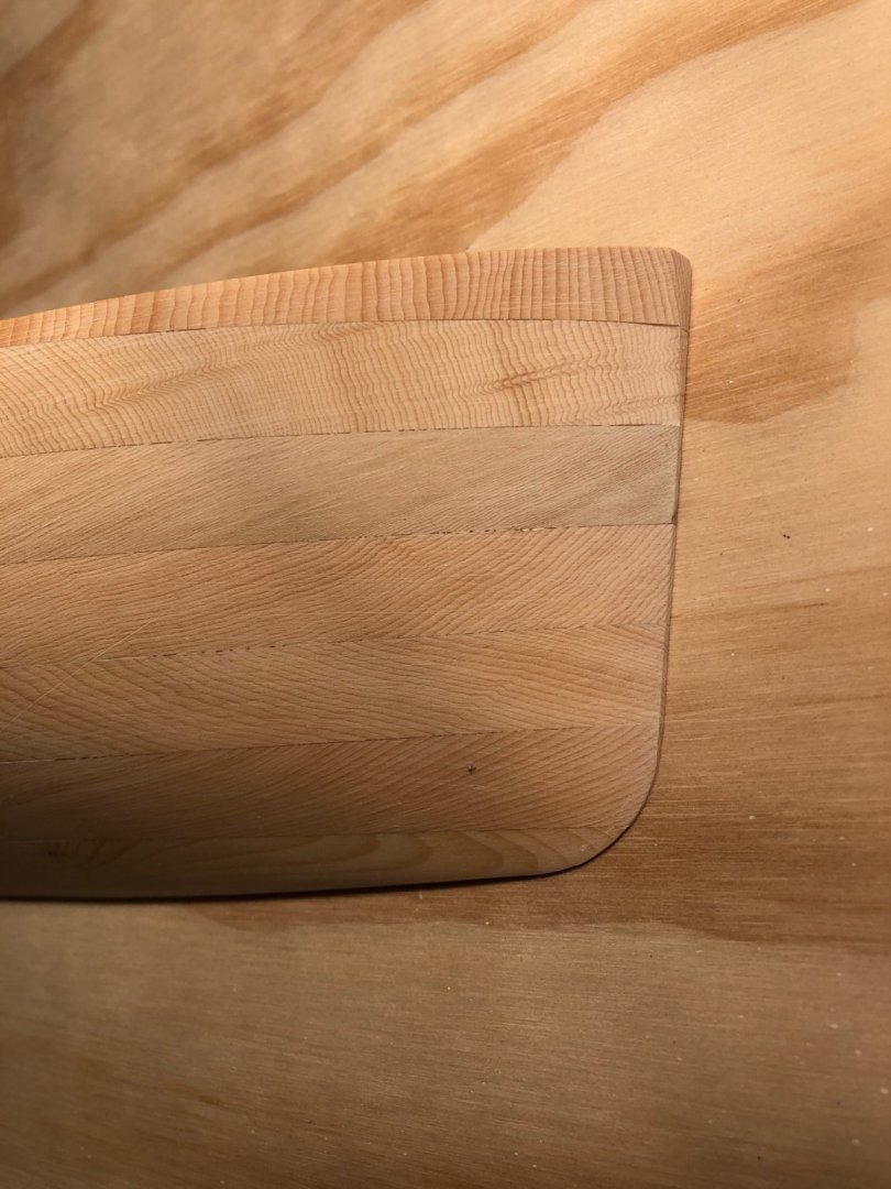
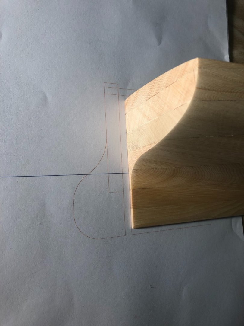
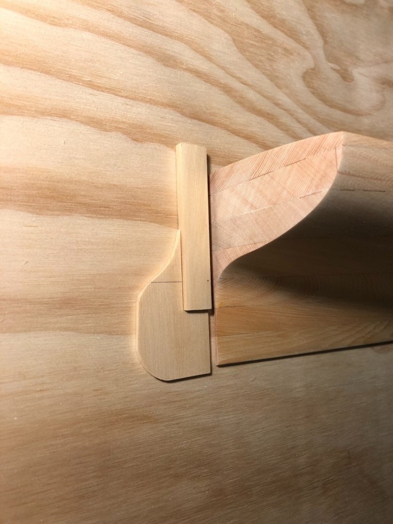
The hull has been sanded to shape, but not the final sanding. I've started making the extra pieces, rudder, tiller etc. I don't think a 'proper' half model has these, being a working tool to refine a hull shape. However, I am going to show them because it will show off a pretty hull all the better. The patch at the bow is difficult to see: But the patch on the topsides towards the stern is quite visible. The bow was done using epoxy with sawdust to colour; the topsides patch was using titebond, no colour added. I thought the titebond would disappear by being thin, however something didn't go to plan. I started with a drawing of the rudder, which is made from a thick stock & a thin blade. The stock tapers away behind the hull as the transom tapers at the waterline. Then made the pieces, unshaped below. The stock will remain squarish, this boat was generally a shapely hull with plain details. The rudder appears to hang below the hull, but I haven't yet added the lower part of the deadwood. That, plus the stem, will be an added strip. Previous patch clearly visible. Hmmm.


-
15' Dinghy by Bedford - FINISHED - 1:1 scale
Mark Pearse replied to Bedford's topic in Non-ship/categorised builds
without the #2 over? -
15' Dinghy by Bedford - FINISHED - 1:1 scale
Mark Pearse replied to Bedford's topic in Non-ship/categorised builds
Hi Steve They are very nicely shaped, remind me of the graceful oarlocks I saw on a Mediaeval long ship build. What oil do you use inside the hull? -
Golly - that's a remarkable boat. The hull appears to be very narrow near the tiller, & it must make some interesting moments for the helmsman when making a sharp turn.
- 179 replies
-
- 2
-
-
- longship
- Helga Holm
- (and 1 more)
-
lovely work Tobias; & the real oarlock is art & engineering
- 179 replies
-
- 2
-
-
- longship
- Helga Holm
- (and 1 more)
-
Hello Tobias Is there any evidence that they protected the planking from ballast?
- 179 replies
-
- 1
-
-
- longship
- Helga Holm
- (and 1 more)
-
I think this an inwale - on the inside of the planking & aligns with the gunwale on the outer side of the planking.
-
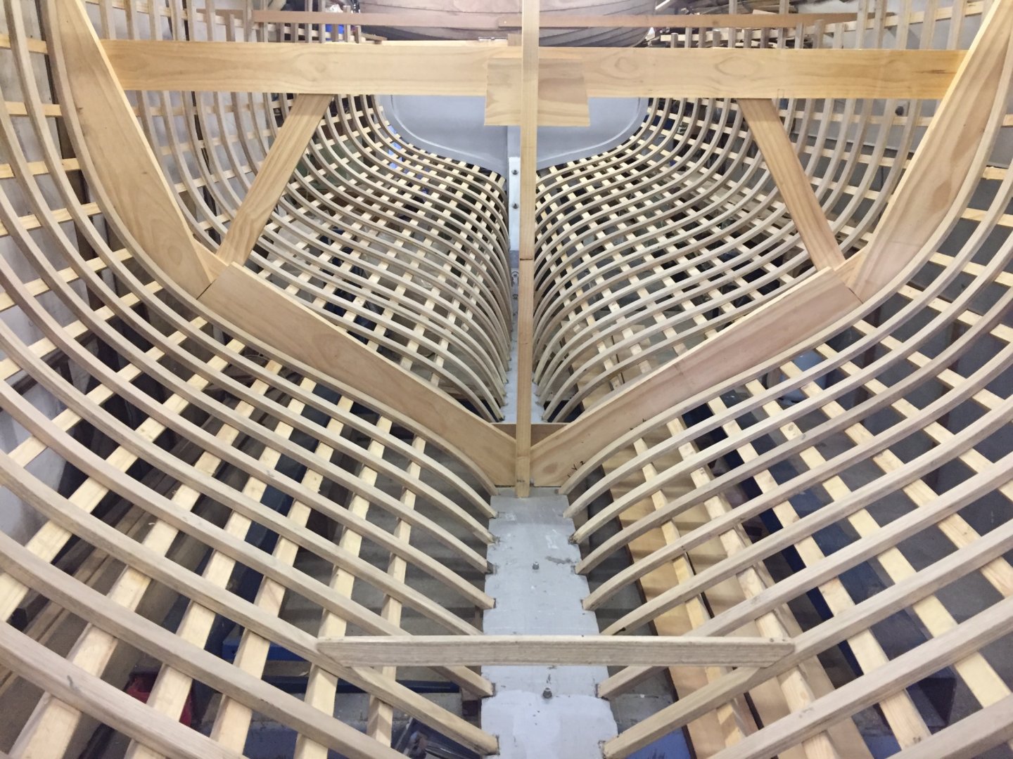
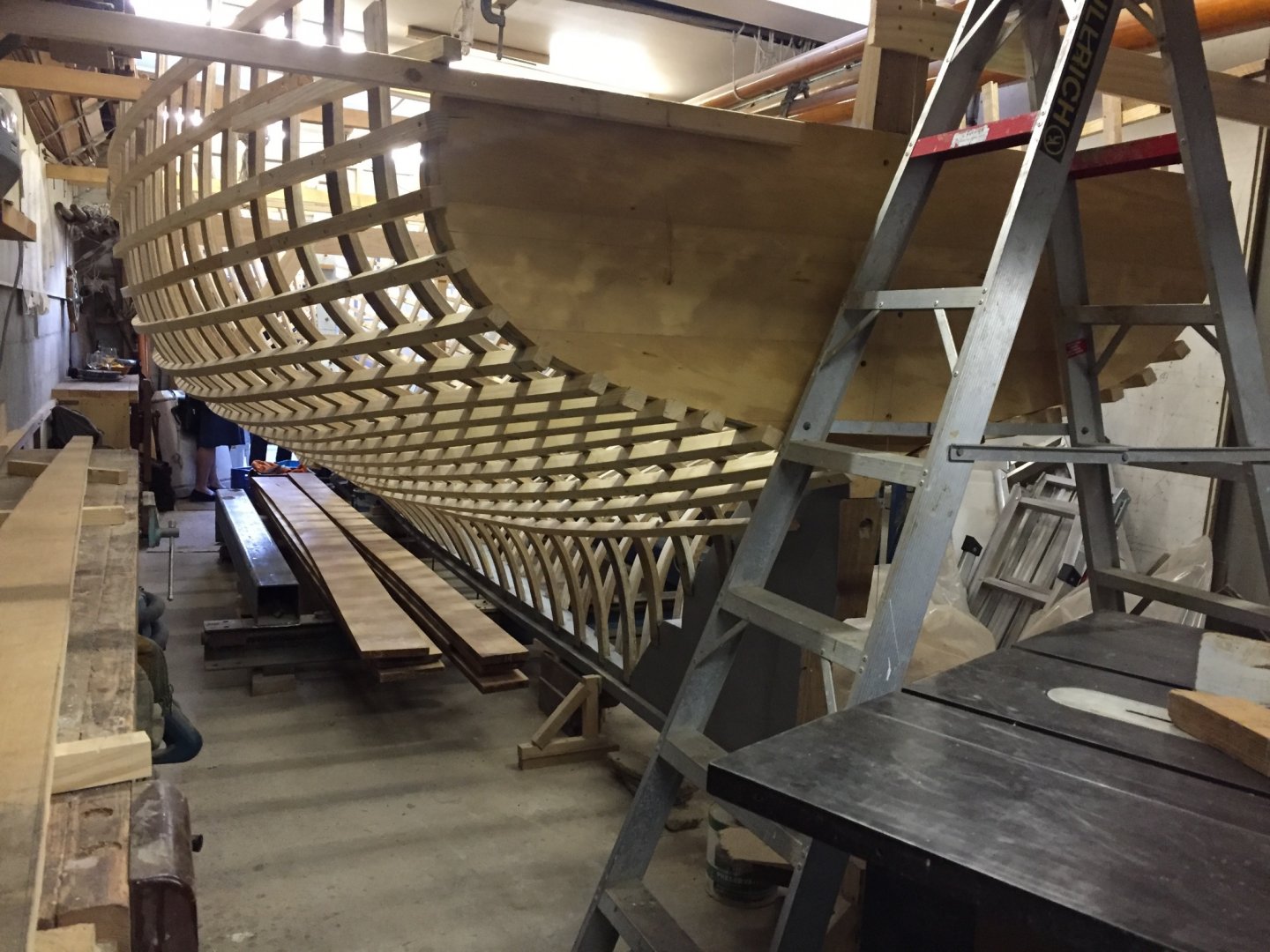
Hi Steve Yes, that's correct & Ian's boat is closely based on Ranger (her lines are a bit fuller than other versions of Ranger). If you search "youtube Ian Smith wooden boats" you'll find his channel, including recent videos on the Ranger build. My photos below are about 2 years ago. This video is from several weeks ago https://www.youtube.com/watch?v=DlJK3pfdWBs
-
perhaps they grew mussels on them, the captain was fond of seafood chowder.....
-
Hi Hakan The rivets have been very successful. Does the lump on the top of the keelson have any function apart from being the middle bearing of the floor beam? I could see something similar in Woodrats build. Also, it's surprising just how quickly the halyards wear the keel away, I wonder what they did when it was really wearing out - whether they replaced a large piece of keel or added a sacrificial piece.
- 179 replies
-
- 2
-
-
- longship
- Helga Holm
- (and 1 more)