Mark Pearse
-
Posts
842 -
Joined
-
Last visited
Content Type
Profiles
Forums
Gallery
Events
Everything posted by Mark Pearse
-
 Hi Vaddoc Nice to see the project back. My eyes are not good for close up work, but an optivisor has been great.
 -
Hi Keith Your machinery skills are a pleasure to follow. On the repair using paint question, wouldn't the deck darken over time but the paint stay the same?
-
HI Steve the work is very delicate. The way you've used two contrasting colours of the timber also looks superb. I like the idea of the stand, but have you tried it upside down? To me it needs a solid base & delicacy where it meets the hull - I like the concept but I think that design unfortunately obscures too much of the hull. The idea of making look like a 1:8 cradle is clever, & I encourage you to not discard the entire concept.
-
a great result Steve, very delicate
-
Hi Steve, lovely work, & it's great how a model is every bit as fascinating as a full sized boat. I'll be following along with great interest for the rest of the ride. PS If you are interested, the Balmain Regatta Sunday week has a waterman's boat event, I'm entering & launching across the bay at Woolwich....be in touch if you are interested, we could meet & row across together all the best, Mark
-
Hi John it's really nice to watch how the feel of the boat increases with each addition.
-
Hi Dick mysterious - what do you interpret the parts to be from the drawings?
- 263 replies
-
- 2
-

-
- nave tonda
- round ship
- (and 2 more)
-
Hi Vaddoc nice work all around, especially the leatherwork details. When you say 'near the gooseneck', I'm assuming that you mean on the boom near the gooseneck. In which case, be aware that you wouldn't usually put belaying pins - or another sort of cleat - on something that moves unless the rope that's going to be tied off there is moving with it. So a sail halyard that goes to the top of the mast can go to a pin or cleat on the mast. You can use a cleat near the gooseneck on the boom, but only for a line that does something on the boom (sail outhaul for example). all the best
-
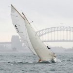
Hi GL that's beautiful, & it really looks like the boat. (It's a photo of our boat Cherub, which is 24' - 4' shorter than the model design, but with the same beam dimension & cockpit size). Very well done & I hope this one gives you encouragement to do some more marine paintings. I'm very glad you liked this photo enough to paint it. Mark
-
Hi Steven speaking as a practical sailor & not a marine archaeologist, I'd say that the reason for the three hole is clear - but I tend to leap to conclusions... One side of that block has 5 or 6 ropes, & say the capacity is 100kg each, the other side of the block needs to be able to take the total load of 500 or 600kg. The point of the block is leverage, 5 or 6 to 1 in this case, but the effect is to increase load. The other side of the block must be able to equalise the load, so it's the standing rigging multiplied to be able to withstand the load of the block - I reckon it's a rope wound around several times to take the load. If my idea is correct, it would be instead of the lateral hole & rope you put in.
-
Hi Vaddoc, a good result, very nice. My experience is that CA can be brittle if there's not much surface area for it to work with.
-
thank you all. Steve, the Maluka to Hobart article here will interest you: https://sasc.com.au/wp-content/uploads/SASC0217W.pdf
-
Hi Steve thank you, it was very good to meet you. I'm glad you enjoyed the event, Cliff's boats are getting more attention & interest these days - the attention is mainly because of their surprising performance in races against boats of any vintage...which is ironic as he designed them more to do simpler things well: fishing, picnicking, camp cruising & single handed sailing. I liked your idea of the scaled Tammie Norrie model - I hope you get to that one.
-
a nice & delicate result Keith - & I really like the way the gold bridges the contrast between the mahogany & white BTW, is it a pure white, or tinted?
-
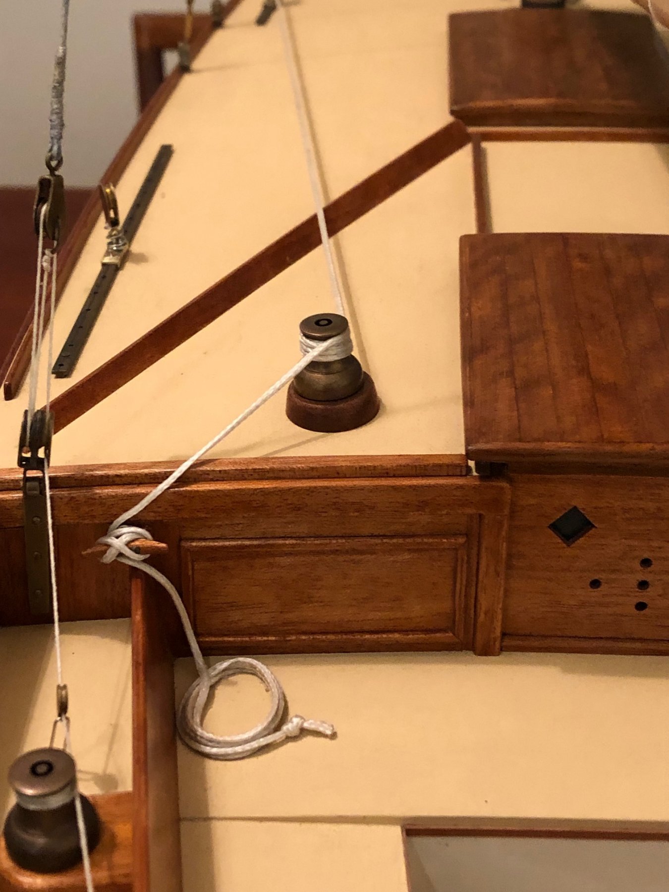
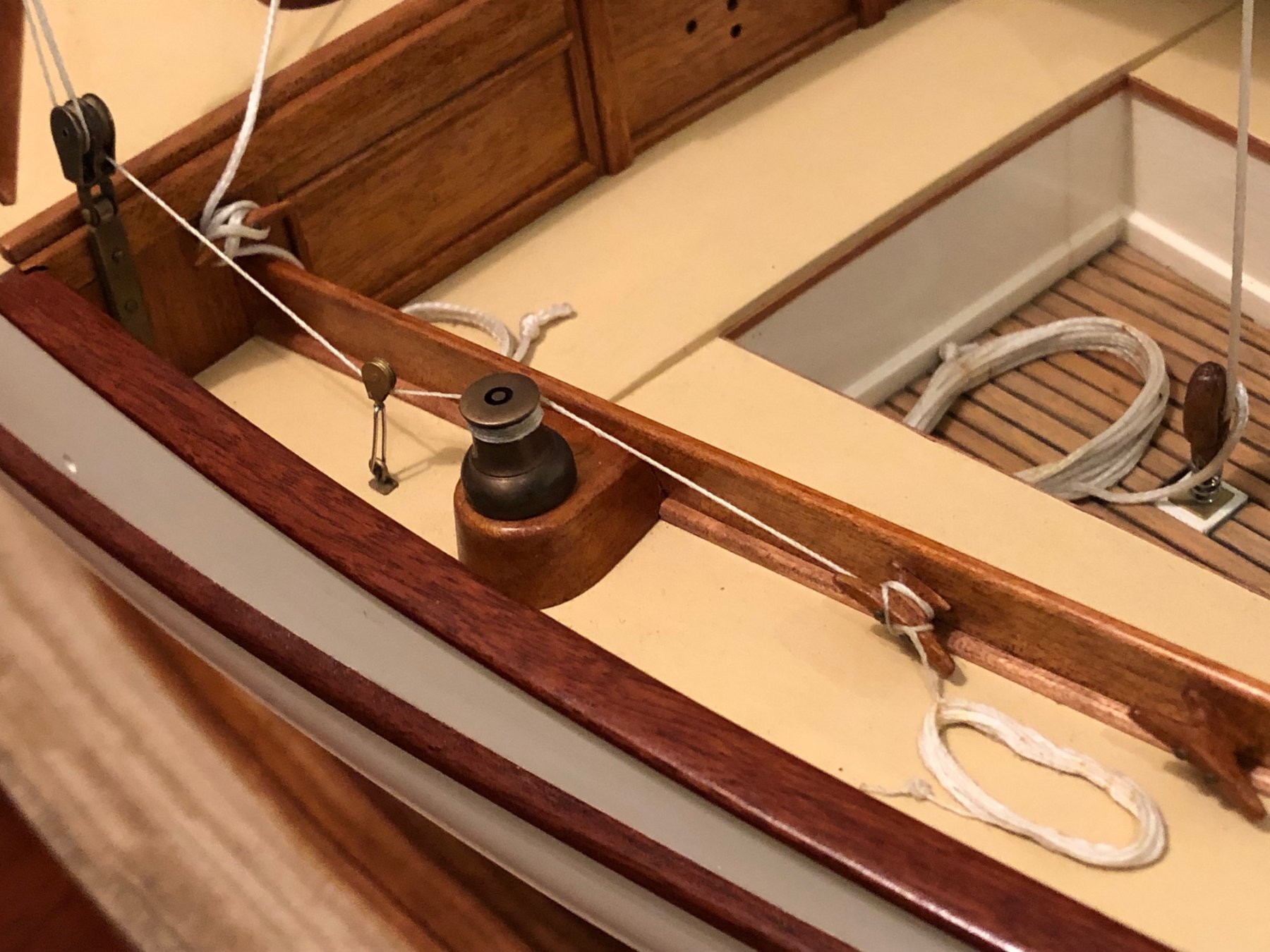
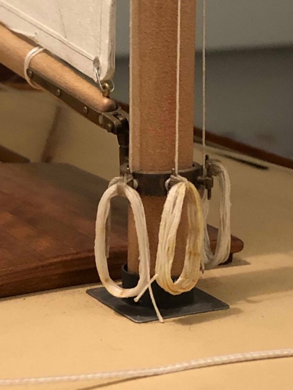
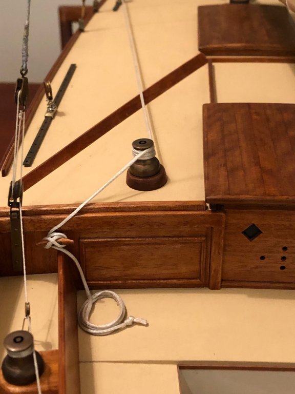
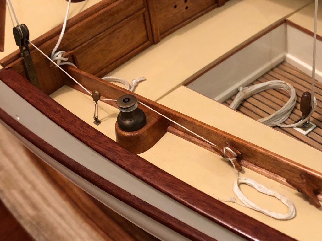
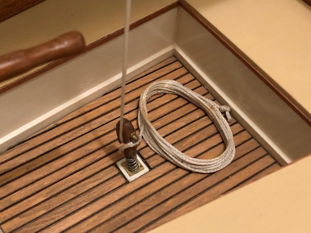
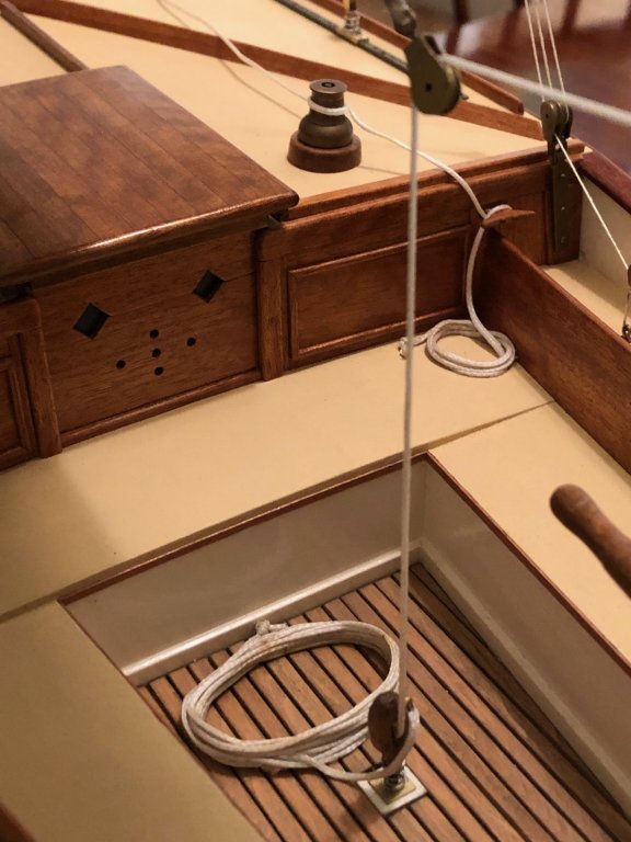
Most of the final details have now been done, but I haven't done a spinnaker pole, & it's an important detail so I'll probably make one. Below are photos of the rope coils etc. Initially I did a couple of coils by winding the rope around a piece of stick & then adding glue - & the result was realistic but I doubt that they would look good on a model. It became clear that the slightly messy yet realistic coils would catch the eye & stand out too much. I realised that the point of doing them neatly is that they don't stand out excessively on the model. The coils were done by drawing an ellipse on a cork base, putting a piece of clear plastic over, & putting a series of pins on the line. Glue was PVA/water about 2:1, then superglue for the lashings & ties. A sharp eye can see that the CA actually stains the thread a little. On some models that might be unacceptable, but I accepted it as part of the ropework colour variations generally. Anyway here's how they came up; halyards coiled at the mast: Running backstay: Jib sheet: Lazy jib sheet, mainsail sheet: Main sheet again: There's a few stains on the thread from the old pins; I scraped some of it off with the tip of a knife but left some on, the odd stain looks quite good.
- 411 replies
-
- 18
-
-
thanks - fascinating & beautiful drawings... & the blokes in the raised stern seem be enjoying their spare time in port.
- 263 replies
-
- 2
-
-
- nave tonda
- round ship
- (and 2 more)
-
Hi Dick, (speaking as someone that is new to these craft) could it be that if the yards were to be lowered for a period, that they are just stowed on the deck & lashed down? If that's not too simple, & it doesn't mean that the crutches don't have a purpose.
- 263 replies
-
- 1
-
-
- nave tonda
- round ship
- (and 2 more)
-
thanks everyone Hi Vaddoc, the sail numbers are self adhesive vinyl cut to order, but there aren't so many places that do 25mm size. I looked at 'Letraset' type lettering but it's more expensive & the range available is limited these days. For the adhesive stuff, you order a few extras & it might not cost any more but it gives you a couple of sets to try your hand with. The transom lettering is also adhesive vinyl, but I had to go to the USA to order them - http://smalllettering.com They were helpful & good to deal with, & likewise I was able to order extras in different fonts/italics etc & then select when they arrived & experiment with the others.