

Chuck Seiler
-
Posts
1,784 -
Joined
-
Last visited
Reputation Activity
-

 Chuck Seiler reacted to Coyote_6 in Prince de Neufchatel by Coyote_6 – Constructo – 1/58 scale - American privateer
@Chuck Seiler Wedges and rigging it will be then! (Thanks for the kind words!)
As far as the rigging goes the "ayes" have it @Dr PR @GrandpaPhil - Chapelle and "The Search for Speed Under Sail" are the plans to follow going forward. Appreciate the assists as always!!
-
Chuck Seiler reacted to rcweir in Pinas by rcweir - Kolderstok - Scale 1:50 - Cross-Section - Dutch 17th Century ship
I like your jig. I'm going to need something like that, too and it helps a lot to have these photos.
Bob
-

 Chuck Seiler got a reaction from Coyote_6 in Prince de Neufchatel by Coyote_6 – Constructo – 1/58 scale - American privateer
Both. On my crappier builds, glue will do. In a model as well made as yours, wedges and rigging.
-
 Chuck Seiler got a reaction from Glen McGuire in Prince de Neufchatel by Coyote_6 – Constructo – 1/58 scale - American privateer
Both. On my crappier builds, glue will do. In a model as well made as yours, wedges and rigging.
-
Chuck Seiler reacted to Dr PR in Masts and Bowsprit - Glue or Not?
Glue isn't needed. After all the rigging is installed the masts and bowsprit aren't going anywhere!
I prefer to install the cradles for the bases of the mast on the keel/keelson and frames for just below the deck planking while the hull is open to work on. I get everything aligned so the masts are aligned and raked correctly. Then when the masts are finally inserted into the hull they will be aligned correctly.
The same is true for the bowsprit. It should have a heel and tenon that fits tightly between the bitts/knightheads, timberheads (whatever you want to call them). This should prevent the bowsprit from slipping backwards between the posts, and it should hold the bowsprit in alignment. If the bowsprit can slip between the posts drill a hole down through the assembly and install a pin to hold it in place.
-
Chuck Seiler reacted to RossR in Masts and Bowsprit - Glue or Not?
I am fairly new to the hobby, so I can’t speak to longevity. On my first build I use PVA, but I don’t think I needed to. On my second build I didn’t use any glue. The bow sprit, foremast and main mast went in straight and are held there by the shrouds. The mizzen mast wanted to lean a little so I used some wedges to get it straight and then relied on the shrouds to keep it straight.
-
Chuck Seiler reacted to Coyote_6 in Prince de Neufchatel by Coyote_6 – Constructo – 1/58 scale - American privateer
A show of hands please - do you folks glue the masts and bowsprit in place or do you use wedges and let the rigging hold them in place?
-
Chuck Seiler reacted to rcweir in Pinas by rcweir - Kolderstok - Scale 1:50 - Cross-Section - Dutch 17th Century ship
In the pictures below you can see the two frames glued up on the keel. The keel was laser etched to help with alignment, and I was careful during the glue up to ensure the frames were perpendicular to the keel and level. When the glue dried I flipped the assembly over and ran the spider test again - i.e. made sure that all four futtocks were touching the glass.
Then I glued in all of the other floor timbers. The kit comes with four spacing "combs" that are used to ensure that frames are spaced exactly right. With the combs, which can be used at any convenient point along the frames, installing the remaining floor timbers is a simple task.
That brings this log up to date with the state of my build. I hope I get some time on it this weekend, but it's not looking too promising at the moment.
Thanks for looking!
Bob
-
Chuck Seiler reacted to rcweir in Pinas by rcweir - Kolderstok - Scale 1:50 - Cross-Section - Dutch 17th Century ship
After assembling the keel and stand, the next step is to assemble the floor timbers and lower futtocks for the forward and after frames. This is a critical step: the shape of the rest of the hull depends on the accuracy with which these two assemblies are made. The kit supplies a printed section of the hull and the instructions say to lay the three parts over their locations on the drawing, and glue it all up. There are no other assembly aids to ensure the positions are correct.
To do this, I started with a piece of tempered glass to have a dead flat, perfectly smooth working surface. I taped the printed section onto the glass and then a sheet of mylar on top of it. The floor timber was stuck to the mylar with double-sided tape over its location on the drawing. On top of that timber I laid the two first futtocks and then carefully checked (with a small square) that each was in the right position over the drawing. Then I stuck a number of wood blocks to the mylar at strategic points to make a jig that would hold the three frame pieces in place during glue up and - most importantly - to ensure that the second assembly was identical to the first.
After both frame sections were glued up, I temporarily clamped them to the keel and turned the structure upside down on the glass: the tops of all four futtocks touched the glass and there was no wobble at all. Comparing the two assemblies front to front showed that, within my ability to measure, they were identical. But, when I compared them front to back there was about 1-½ mm difference at the turn of the bilge. I thought about that for a while, but decided that it probably doesn't matter if the two sides differ slightly - the two sides are going to be constructed quite differently anyhow since one side is planked and the other just open frames. The deck beams, of course, might have a different opinion - we'll see.
Bob
-
Chuck Seiler reacted to tlevine in NRG Rigging Project by tlevine
Most kits come with deadeyes and partially completed chains. Usually, the upper link (the link that goes around the deadeye) is pre-formed, with the bottom cut for insertion of the deadeye. Wire is provided for the builder to form the other two links but the entire assembly has very little strength and the cut ends of wire are ugly. The only way to make this assembly stronger and better looking is to solder the links closed. I prefer silver soldering, even though regular soldering will give sufficient strength. The benefit of silver soldering is that the metal is fused together rather than connected by a dissimilar metal, tin. This makes it easier to bend the part without worrying about the solder joint breaking. The downside is that there is a learning curve and the tools are more expensive. Silver solder also blackens well. There are also low melting point silver bearing solders (Tix) which can be blackened.
The measurements for all the parts of a British warship were determined by the Admiralty. There are reference books that contain this information such as Steel’s Tables. An easily read version of the tables is sold in the NRG store. The main mast diameter is given on the plans as 18”. Using the information from the tables, I determined that the main stay is 9” and the shrouds are 5.5”. Lines are measured by their circumference. The diameter of the deadeye is 1.5 times the size of the shroud or stay it is attached to, in this case 8 ¼”. A spreadsheet comes in handy in determining all the measurements.
Let me start by saying that my metal work has a bit to be desired. The chains are made from 1 ¼” wire, which is 22 gauge. I temper the wire by drawing it through a gas flame until it glows red. This makes the wire more malleable and removes any factory applied coating.
The deadeye chain is the same length for all the deadeyes. Make one and use it as a template for the others. I wrapped wire around the deadeye, leaving long tails, and inserted this into the slot in the channel. The tails were cut long enough to be able form the loop below the channel. I removed the deadeye and applied a finish.
The lower links are all the same length. From the plans I knew that the toe of the lower link is bolted 5” below the top of the wale and that its overall length was 9”. Two T-pins were inserted into the soldering board and the wire was wrapped around them, with the cut ends on the side. The middle link is different for every shroud because each is at a different angle to the mast as seen in the two pictures below. The link becomes longer with greater angulation of the shroud. You can see the difference in the shroud angles and how this would affect the length of the middle link.
To determine the angle of the chains, I put masking tape on the hull above and below the channel. A loop of rope was placed over the mast head and inserted through a slot in the channel. The angles made by the shroud were transferred to the tape. I dimpled the wale where the toe of the lower link and the lower preventer chain bolts will be located and removed the tape.
A hole was drilled through the wale where the toe of the lower link would later be bolted. The lower link and deadeye were temporarily installed. The length of the middle chains was determined by trial and error. With the deadeye and lower link in place, I formed the middle link from rope the same thickness as the wire and transferred those lengths to wire. I formed the middle link and soldered it closed, keeping the joint on one of the long sides. Then I inserted the lower link through the middle link and soldered it.
A T-pin was pushed into the soldering board and used to form the lower link toe. The lower link is also bent at the toe, allowing it to lay flat against the wale.
Finally, the wire for the upper link was passed through the middle link and soldered. The deadeye was inserted into the loop and the wire was crimped around it to fit into the channel slot, placing the solder joint in the slot camouflaged it.
And here are the ten chains, ready for blackening. The blackening chemical did not damage the wood deadeyes.
After blackening, the chains were installed. I have a piece of wire temporarily holding the lower link to the wale.
The preventer plate prevents the bolt securing the lower link from going all the way through the toe. It was made from square bar stock that was forged to the correct shape. Mine are made from sheet brass, cut and filed to the correct shape. Just like the middle links, they varied in length. The top of the plate makes a step over the bottom of the lower link toe to cover it. To determine the distance between the bolt holes on the plate, I measured the distance between the toe bolt and the previously marked lower preventer plate bolt and added the diameter of the wire the link was made from. The sequence is shown in the drawing below. After they were finished, they were blackened and installed.
To hold the upper links in the channels, a strip of molding was placed over them. Next up, the rigging begins.
-
 Chuck Seiler got a reaction from ccoyle in Gunboat PHILADELPHIA 1776 by Chuck Seiler - Scale 1:48 - from Model Shipways plans
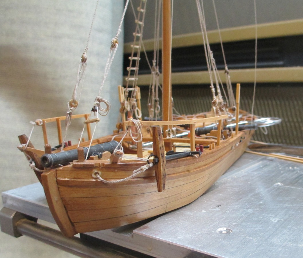
Philly at the Fair.
I got some horrendous "blooms" from reflection. Sunday (when I am back at the Fair) I will see If I can remove the case and get some shots. Meanwhile, I tried to blot out the worst of them.
I managed to eek out an honourable mention.
-
 Chuck Seiler got a reaction from robert952 in Are you an NRG Member???
I suspect some of that 40k+ number are those that joined, stayed for awhile and just never returned.
-
 Chuck Seiler got a reaction from Scottish Guy in Are you an NRG Member???
I suspect some of that 40k+ number are those that joined, stayed for awhile and just never returned.
-
 Chuck Seiler got a reaction from Ryland Craze in Are you an NRG Member???
I suspect some of that 40k+ number are those that joined, stayed for awhile and just never returned.
-
Chuck Seiler reacted to Coyote_6 in Are you an NRG Member???
That free Zoom presentation for NRG members with Ian McLaughlan on "The Sloop of War" last month or so was fabulous. Worth the cost of admission right there.
I know I wouldn't be nearly as far without the MSW and NRG family - you guys rock. Member if you can or want, and just continue to post and share if you can't or don't want to.
Oh yeah, and like $2 off on NRG's uber-legible "Steele's Tables" was awesome as well.
Love this corner of the internet.
-
 Chuck Seiler got a reaction from Keith Black in Are you an NRG Member???
I suspect some of that 40k+ number are those that joined, stayed for awhile and just never returned.
-
 Chuck Seiler got a reaction from mtaylor in Are you an NRG Member???
I suspect some of that 40k+ number are those that joined, stayed for awhile and just never returned.
-
 Chuck Seiler got a reaction from Nirvana in Are you an NRG Member???
I suspect some of that 40k+ number are those that joined, stayed for awhile and just never returned.
-
Chuck Seiler reacted to Snug Harbor Johnny in For Beginners -- A Cautionary Tale
I'll tell you a good model to start with that many on the forum may agree with ...
-
Chuck Seiler got a reaction from Scottish Guy in For Beginners -- A Cautionary Tale
In my opinion, that which makes a log good also makes it hard to keep up. I have often gotten bogged down on a model because I am taking so much time and effort to get pictures at the right point, get thoughts on paper and compile a good post. I don't know if that ever came through in my logs, but I tried.
Here is what I think makes a good post:
Explain what you are doing as you go along. Looking at pictures of how your model is progressing is nice, but looking at the process you are using to get to that point is even better. How did you make that thingamabob? What problems are you having? Detailed info on how you make something can be enlightening. There is a fine line between going into TOO much detail and no enough. I have seen things that I have tried to make many times and I cannot get them to look that good. How did you do it? I guess that is what IMs are for.
A lot of pictures. Close ups, full model, different angles, high resolution. The latter is important particularly when illustrating a lot of detail. I find it frustrating to click on a photo to blow it up, only to find it is not very large or poor quality. My rule of thumb when I was a newsletter editor was I should be able to expand the photo to 200% and still get good detail. Different angles are good. I have been trying to find some shots of where the wales come together at the bow, both sides. I cannot find many. Most shots are of one side or the other, but not both. Same goes for other areas we don't normally see.
In my opinion, a very good example of a good build log is Dan Vadas' "VULTURE" log.
PS. His VULTURE cross section isn't bad either.
-
Chuck Seiler got a reaction from Scottish Guy in For Beginners -- A Cautionary Tale
I think it is because they have a few moments to take in the entire model, whereas you have had hours to create, then agonize over that mistake (and the 3 mistakes you made trying to correct the one mistake).
I look at my PHILADELPHIA model and look at the many rope coils. A casual observer would say "Wow! A lot of rope coils" and move on. I will look at it and remember how THAT coil took 3 tries to make. THAT coil replaced the one I made and somehow lost. THAT coil I accidentally glued to my finger.
-
Chuck Seiler got a reaction from Scottish Guy in For Beginners -- A Cautionary Tale
Roger,
Well said. You are EXPECTED to make mistakes on your first one, that's why is should be something like the Virginia Pilot Boat (or whatever is on sale). I have had several early models where I have essentially made twice. Build a part, throw it away, build it again. Build an assembly, tear it apart, build it again. The value is in the learning.
-
Chuck Seiler got a reaction from Scottish Guy in For Beginners -- A Cautionary Tale
I would not recommend this. I believe I would have been ill served if I had been forced to go into the kiddies pool until I learned how to swim when I first signed aboard. Being able to see the various levels of accomplishment helped highlight what I was getting into and let me know there were many like me. Meanwhile it also gave me a goal to strive for.
Looking at the build logs of some of the more accomplished modelers helped me learn the terminology and gave me an appreciation for the quality that could be achieved. I was also able to take away little pieces of "how to do it". I may not be able to build a whole model like a master, but I can plank like one (that's my story and I'm sticking to it), or I can paint like one, or make thingamabobs like one.
Throwing out a question while bobbing around in the main pool ensures that everybody sees it. If there was just a beginners section, the question might only be seen by other beginners and those veterans who might specifically be there to do some mentoring.
I see nothing wrong with the way it is now. Just my 2 euro's worth.
-
Chuck Seiler got a reaction from Scottish Guy in For Beginners -- A Cautionary Tale
Jud,
I strongly disagree. I take Chris' original post for what it is, a warning. I provide the same warning anytime I speak to a perspective modeler, whether it be at a club meeting or at our Ship Modeling booth at the county fair. Most people don't realize how difficult building a wooden ship is and how many sub-skills need to be developed before you can do a bang up job on a complicated model.
As seasoned modelers, we owe it to them to give them reasonable advice.
-
Chuck Seiler reacted to kurtvd19 in Are you an NRG Member???
Something that we offer to members are the Virtual Workshops we offer throughout the year on Saturday mornings (10:30 AM Central). We record the workshops and within a week or two they are available on the website for members to view as often as they want.
We have a new workshop on May 4 on Basics of the Air Brush. We also have a two part one on June 15 on Creating Realistic Working Sails and Creating Furled Sails. Check out the recordings in the Events section of the website. Also, they are priced right - FREE! All members will get an email with the Zoom link real soon.