HOLIDAY DONATION DRIVE - SUPPORT MSW - DO YOUR PART TO KEEP THIS GREAT FORUM GOING! (83 donations so far out of 49,000 members - C'mon guys!)
×


*Hans*
-
Posts
465 -
Joined
-
Last visited
Content Type
Profiles
Forums
Gallery
Events
Everything posted by *Hans*
-
 Hey Vivian, what about if I send you some right sail cloth and you make one of your nice hot jalapeno dishes in return? (although sending cloth to Brasil is easy, but sending food to the Netherlands is very difficult). Please post your updates - we're eager to see!
 -
And for the stops on the servo I would go for a mechanical stop at the gate arm, with some flexible connecting in between the arm and the servo - in case the servo would turn a bit more then 180º But that's me - being a mechanical engineer (with some interest in electronics).
-
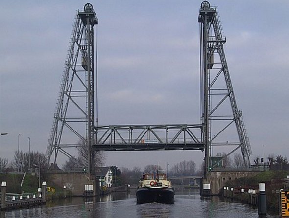
I think the type of bridge is a very common one - used all over the world. This one is in the Netherlands - close to Alphen a/d Rijn
-
Ohw - nice! I used to learn these kind of things at University, but have forgotten almost everything of it, it seems. Maybe you could use some fixed stops at the servo to achieve the 180º
-
Hey Tecko, what a nice (no - superb) building is this! I like it not only for the model work you are doing, but also all the electronics wiring and mechanical parts in it. Chapo!
-
Tecko, thank you! As said - I'm busy with some other ships as well, so it might take some time.
-
Hello Messis - thank you! The oars are something which will be done somewhere in the end of the build. So you have to wait for some more time - sorry! I am currently working on three different vessels, so it goes all a little bit slow.
-
Hi Anton! Long time no see. Is your Leeuwin already finished?
- 322 replies
-
- 3
-

-
- sergal
- sovereign of the seas
- (and 5 more)
-
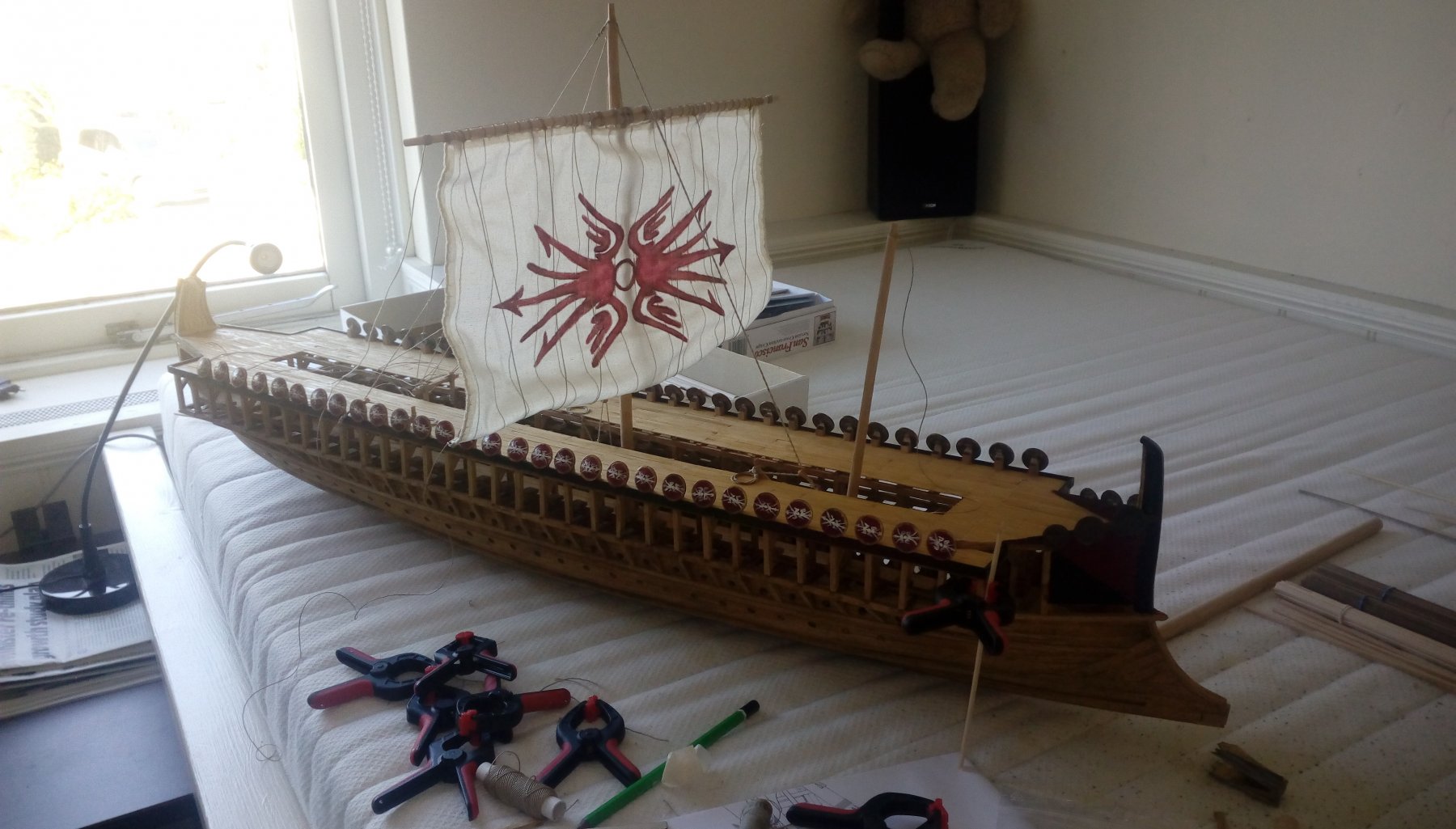
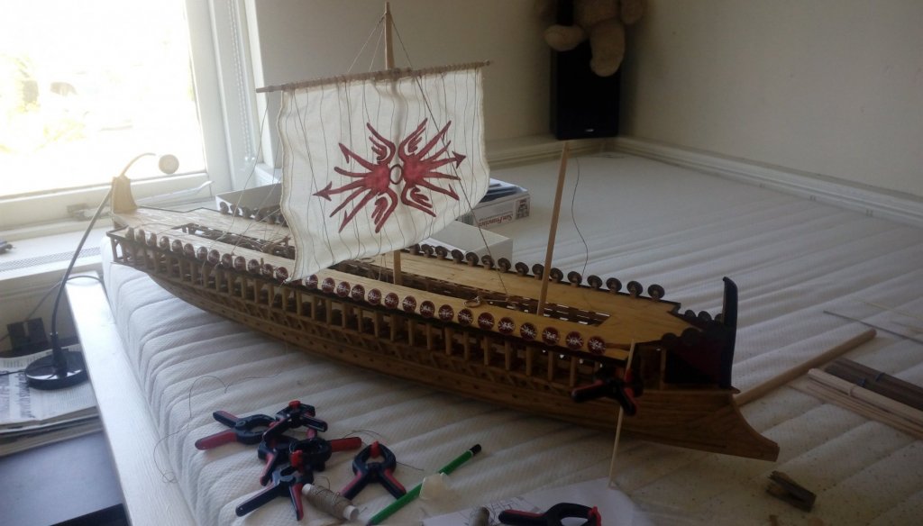
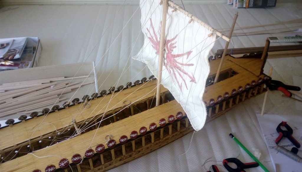
As I am working on three ships at the same time it all goes a bit slower (beginning of May we have a little show with ancient sailing ships in Rotterdam, NL, and I want to show four vessels which all have to be in some state of finish). The Trireme fits very good to this show - as she has one of her sails attached:
-
I drill four small holes on the four corners (about 0,6 - 0,8 mm) - in such a way that the hole is complete inside the outlines of the gun port. Then cut out with a sharp knife and as last thing with a square file make the corners square
-
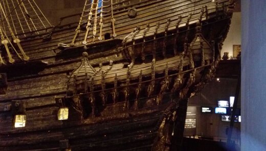
We can start a nice discussion about this - as a parallelogram shaped gun port where the turning axle of the hinges are not in the same line simply cannot be opened. Two hinges beside each other need the same axle line to function properly. And if you mount the hinges under a specific angle so there turning lines are the same then the form of the port gives trouble to open. The vertical sides of a gun port were vertical - that's correct, but regarding the horizontal lines: the lower one could follow the deck (but this was surely not always the case), but the upper one was always under a 90º angle with the vertical sides. So a square gun port is very original. Attached a photo of the Vasa (Wasa) which is the excisting proof of how it was done (this is the original ship from 1628 - same time as the Batavia). Due to the back light the form of the gun ports is clearly visible.
-
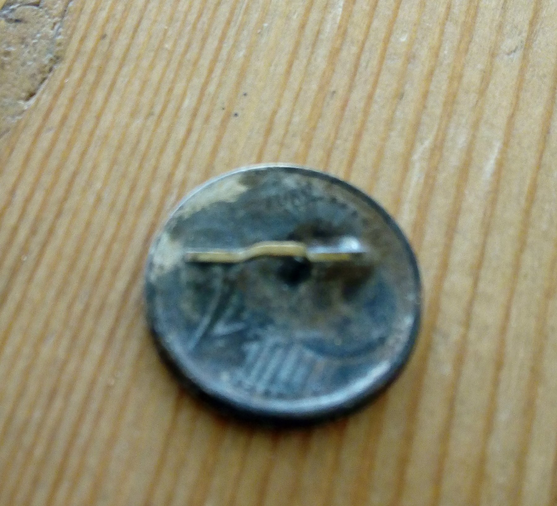
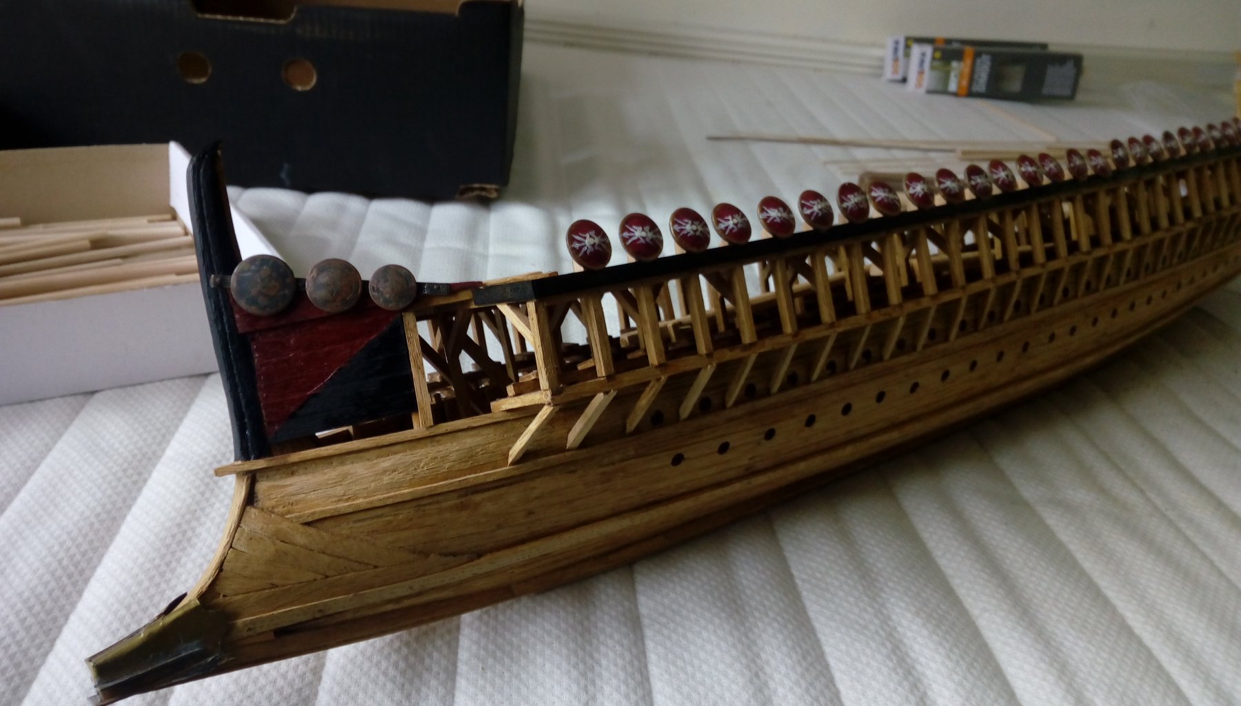
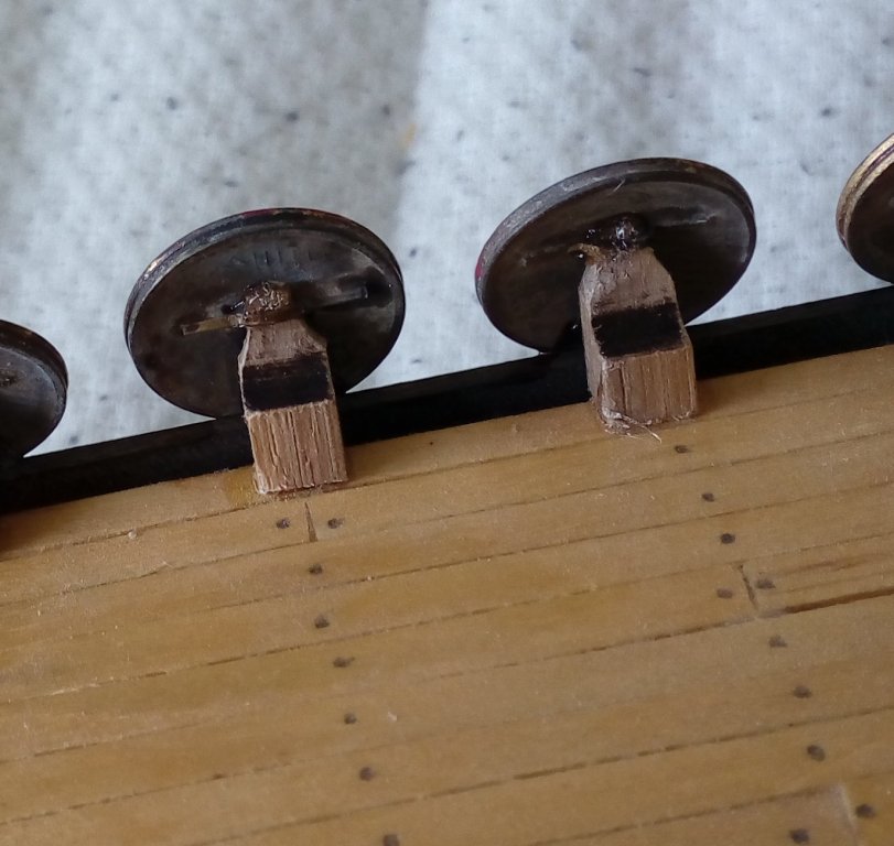
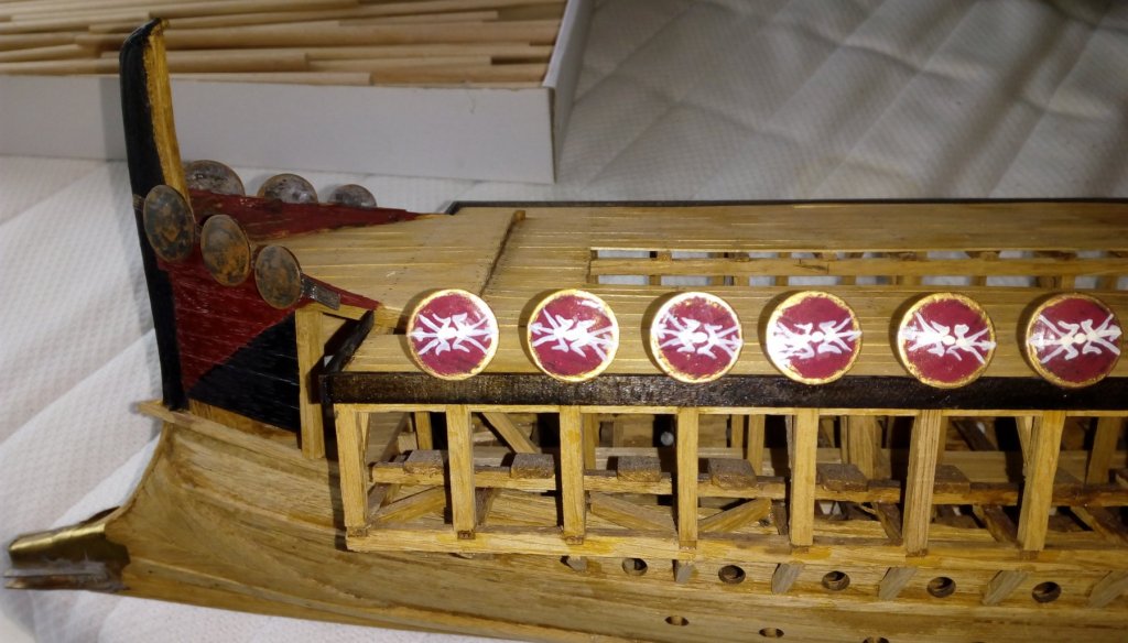
Made them with my cell phone, so not the highest quality - sorry. Backside of the shield. These are in fact 2-cent coins - made convex - tinned and then soldered a small brass handle onto it. On the ship itself I have placed poles - with a sharp end sanded to it: And the shield can be put with its handle over this pole: It looks a bit fuzzy due to the glue. Normally it should not be glued of course, but I don't want them to get lost during building etc.


-
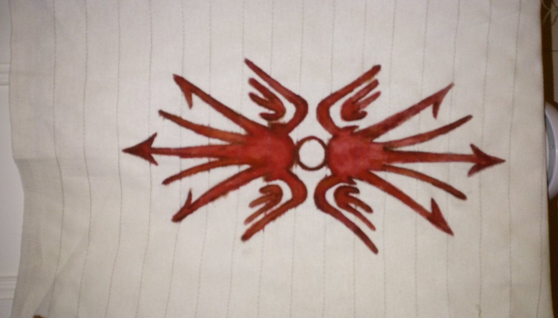
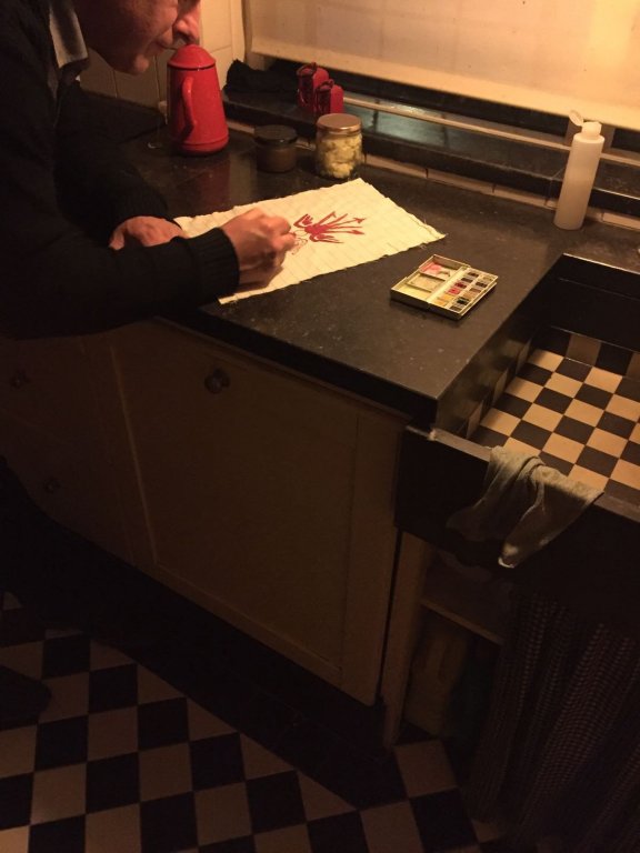
Modelling is a lot of standing for me (I don't like sitting and doing things). Standing in the kitchen, doing some art work: This is going to be the main sail:

-
Hey Robin, Didn't have a look at your Bireme build until now. Looking good. I made a Bireme as well for my son (ho studied archeology) and than started a scratch trireme in the same scale. This turned out to be a huge thing of about 1 meter length. Picture of how far I am now:

- 473 replies
-
- 11
-
-
- greek bireme
- dusek
- (and 1 more)
-
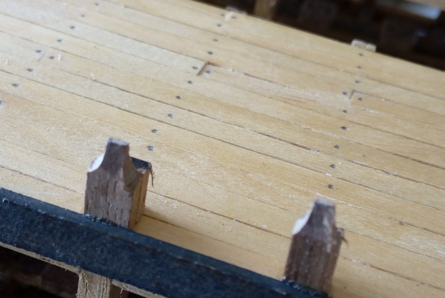
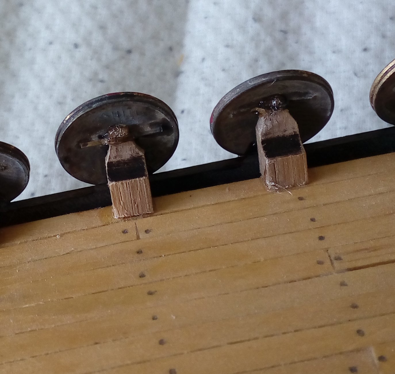
I sanded a sharp tip at the side-end of small piece of oak 3x3 mm (roughly 1 cm length) and glued this pole onto the deck. The shield has a handle on the backside and this fits onto the sharp end of the pole. In this way the shields hang loose on the side, so they could easily be taken of when needed during battle. In my case the shields are glued onto the pole so they stay in place. But mind you: there is no evidence whatsoever that this was done in real. It is just my imagination that this could have been done in this way (and it gives a nice extra to the model).
-
Beside all the other projects I am doing I just did something on the Trireme as well (again). The shields (60 of them) have been made, painted and given a personal touch. One side of the ship is now done in the way as described earlier in this topic.

-
Which is in fact the best way to do it. After knotting the first ratline just put the planks on top of it - correct the level when necessary and knot the second ratline. Correct the level again by tapping the knot a bit down or up - white glue over it (you can do this in the end as well) and proceed to the top. Another fact almost no one knows: due to shrinking of the rope the ratlines always had some more length than the space between the shrouds, they always hung a bit loose. So don't knot them as tight as possible - and the hourglass effect will not occur as well. Nowadays, with other qualities of rope it is different of course.
-
The most simple solutions are often the hardest ones to find...
-
It is such a simple and easy solution for making the ratlines! (and sorry to say John - I did it in exact the same way as you did - already some years ago for my Batavia ) And you say you are a novice - but seeing your pictures I don't believe you... Regarding the space between the ratlines we've had some discussions here the last years. Was it a step of roughly 30 cm - or 1ft. (and many steps to get up) or was it more onto a step of 50 cm (1,5 ft.) The Dutch were known as a bit scrooge, frugal (well, let's say economical) and bigger steps meant quicker on top, so less time wasted - and less rope! So I go for the 50 cm. If you use a 6 mm plank (how many inches is that?) on a scale of 1 to 72 (which the Batavia kit is) you end up with a distance of 43 mm. Including the knot and correction in level to my opinion you are pretty good in line. If you have a 1:50 model take 8 mm planks, and if you are building at a 1:100 scale a 4 mm plank is the right one.
-
Vivian (and all the others), Thank you for all the likes. This topic is a bit messed up due to the fact I am currently building three ships at the same time...
-
It has indeed been a while since your last post. Nice to see you back :-)
-
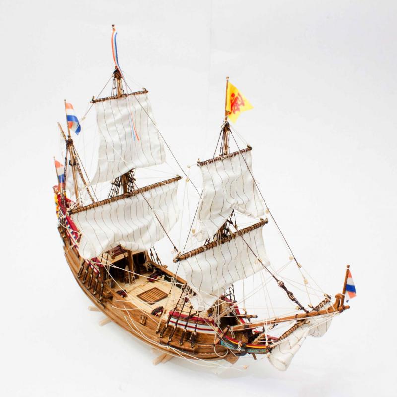
@Carl, Size of the model: approx. 65 cm long (including sprit), 55 cm high, 25 cm width - which is actually a very reasonable size. Not to big to fill the whole mantelpiece, but also not to small to get lost in the corner. @Steven, she is a pretty cute ship, indeed! I was very pleased by the shape and looks of it during my construction. If I find some time I will start an after-build topic about the Duyfken.
-
My last post here was in januari, and now we're talking september. Haven't done nothing in the meantime though. In januari I started the scratch build Duyfken 1595 - finished it in July and made it into a model kit which is now available: I think I should do something on the Trireme again...
-
Piet, What a great picture is that! I really do like it - but can't tell why. Maybe because it reflects the old days when the world was going up again after WW II (won't say it was a better time than it is now - but sure it was going forward). The picture behind him - 6 kids, and when I look close 5 girls and one boy - am I correct? One of them must be your wife then. The radio on the wall! We have the same one here on our dresser. Unfortunately it doesn't work anymore, but it is the real type - with radiotubes. (btw - still playing my music via a tube amp - but that is "hot" again). Ok - drifting away - I am getting older as well. But I like the info on the Musi as displayed here above!
-
I think Piet is going to build a Cliffhanger....