


schiffebastler
-
Posts
322 -
Joined
-
Last visited
Content Type
Profiles
Forums
Gallery
Events
Posts posted by schiffebastler
-
-
Hello everybody,
it is going on with some parts of the bowsprit.
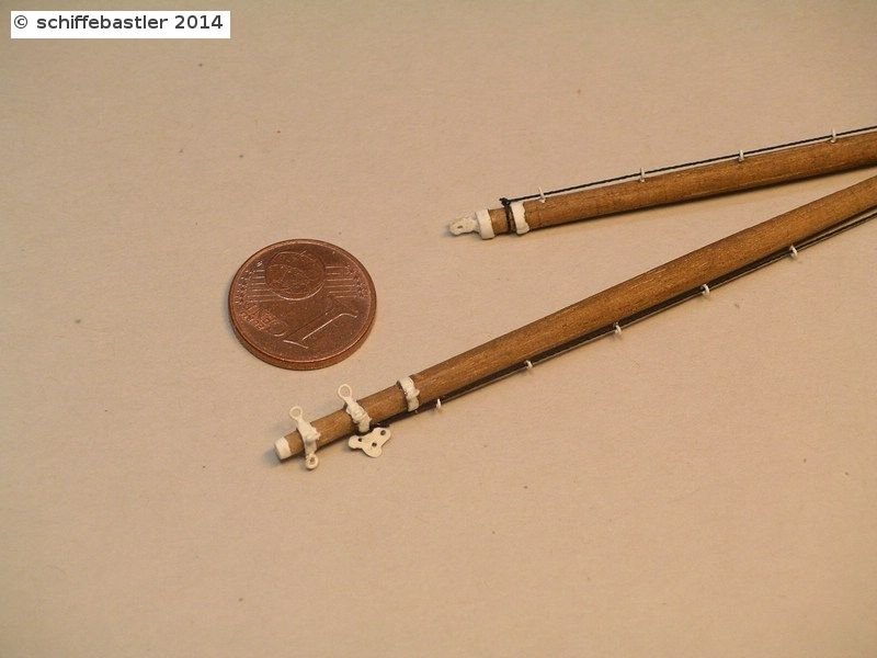
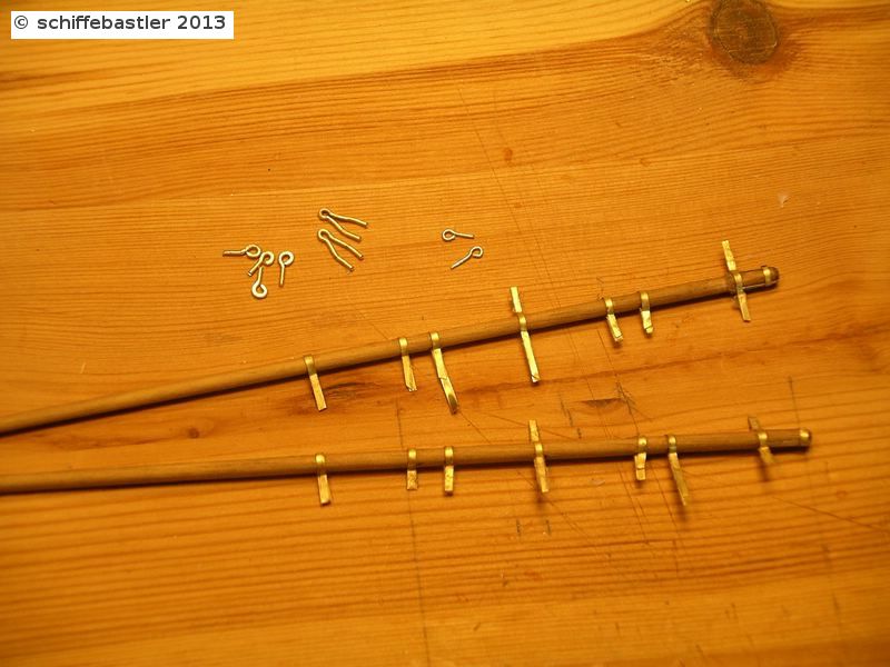
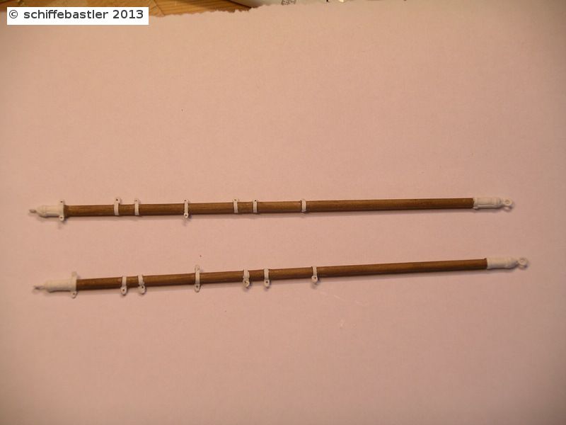
The Amerigo has two spares which are fixed to the right and left of the martingale boom where some ropes are fixed. Unfortunately, I don't know how it is called.
Some parts are soldered, which has been quite difficult because the metal sheet is only 0.1mm thick...
but ofter some tryes, I succeeded.
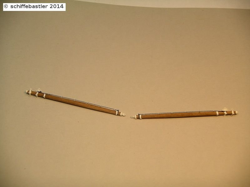
Along both spares there is fixed a rope. Later there will be fixed a net at those ropes.
Regards, Joachim
-
Hi Lars,
thank you very much for your interest. I'll try to proceed quickly with the next steps (hope I succeed
 ).
).Regards Joachim
-
Wish you also a happy new year! Well done Lars, I like it!
Bye, Joachim
-
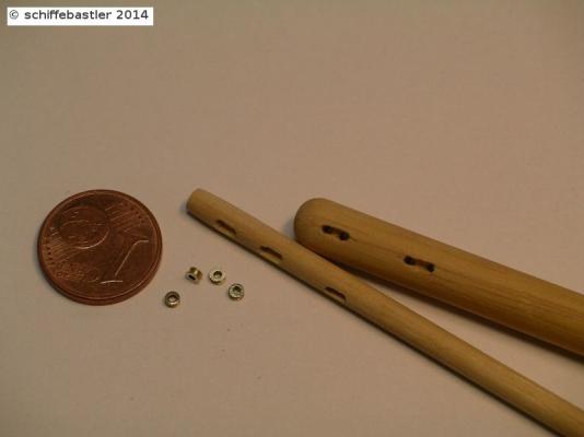
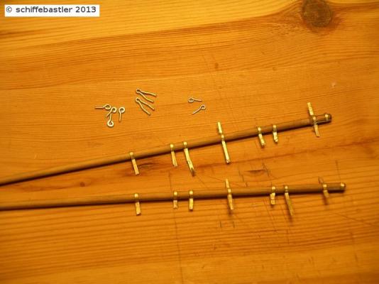
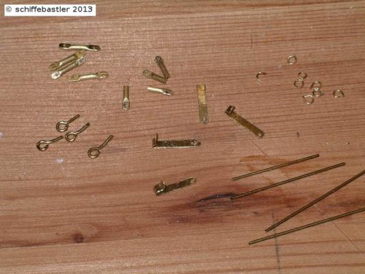
Now, a small continuation. The martingale boom usually is not spectacular but it still took me some time with all the small parts.
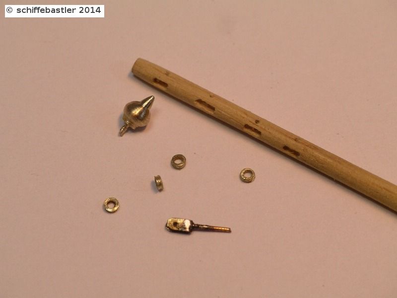
On the first picture you can see some of the parts, e.g. the 4 reels with an width of 0,4 mm. On the top there is a metal part to connect the boom to the bowsprit. The parts are soldered together.
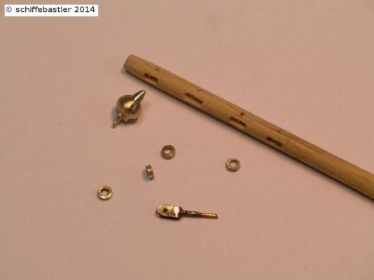
Below there is a golden part at the end of the boom. I produced this from a small part of brass and painted it with golden colour.
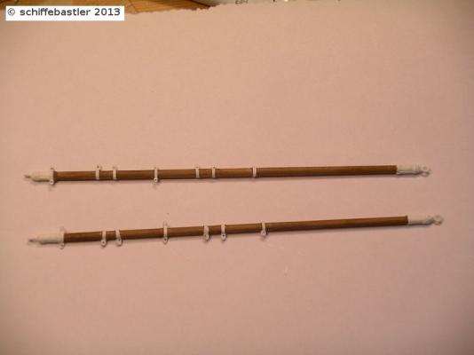
Here you can see the final boom with all parts, also some metal part which contains eyelets where chains are connected later.
So far today,
Bye Joachim
-
Thank you Michael, it is really necessary to produce own ropes. The kit contains only 2 types of ropes, a black and a brown one...
For the Amerigo I need about 10-12 different types and those I cannot bye with the necessary size and quality.
As mentioned before, I could not use any rigging plan of the kit, the reality is quite different from these. So it took lots of weeks, and still will take weeks to achieve good and correct plans of the rigging.
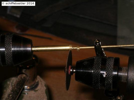
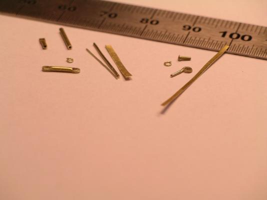
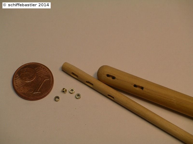
Now I start with the bowsprit. So far it is still a very rough shell. One of the unimpressive parts are the thimbles where I need hundresds of different sizes. How you can see on the picture, I use brass tubes in different sizes from 1 to 3 mm diameter. With two drill machines I sand a small groove in it and cut it. On the picture you can see the biggest ones.
The bowsprit contains of 3 spares, the biggest two on iron and the last one on wood. There are different reels which have to be put into the spares. Theese have a diameter of 1,2mm.
Beside of theese there also needed a lot of metal parts in order to connect the parts of the bowsprit together and fix ropes on it. But as you can see, all parts are not ready so far.

And now, to get a first impression of it ....
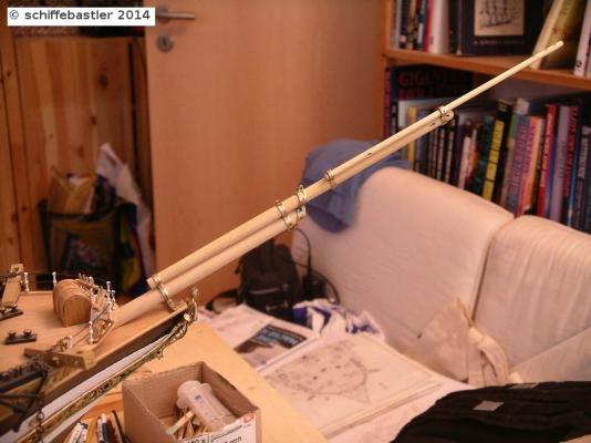
Bye, Joachim
-
Again and again I am astonished about the fantastic results you achieve with your work. Based on a good kit you manage to achive a much higher level than any kit could supply.
regards, Joachim
-
Thank you very much, Greg!
Bye Joachim
-
At least a flexible holder for yards. Within this holder the yards with different length and thickness can be fixed. The it is easier to fix all the different small part, where always an additional hand is missed.
 Now I wish you all a happy new year!Bye Joachim
- dafi, WackoWolf and popeye the sailor
-
 3
3
-
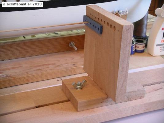
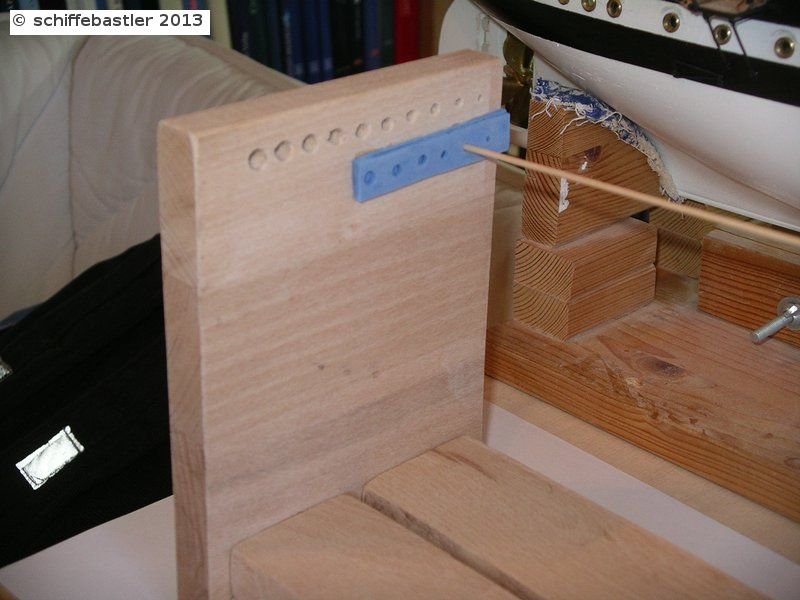
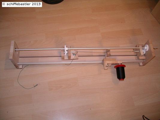
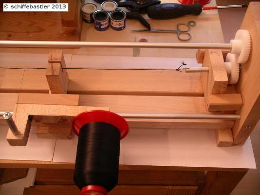
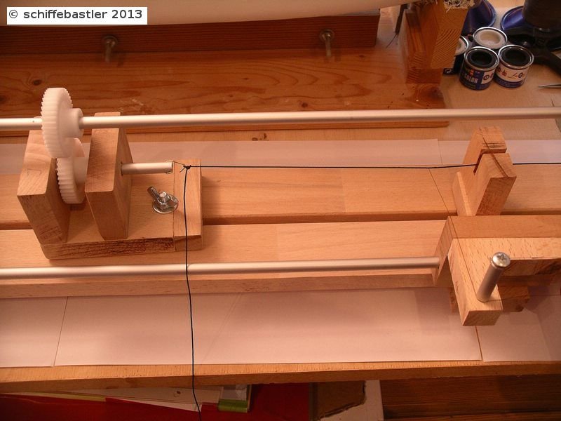
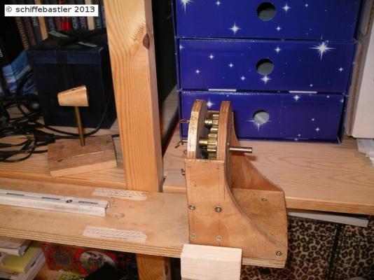
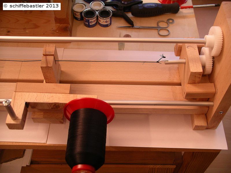
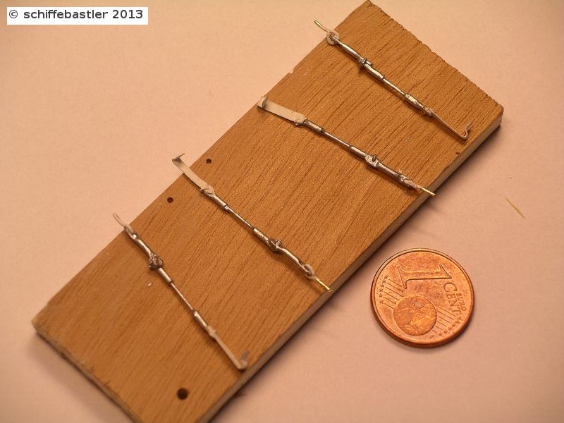
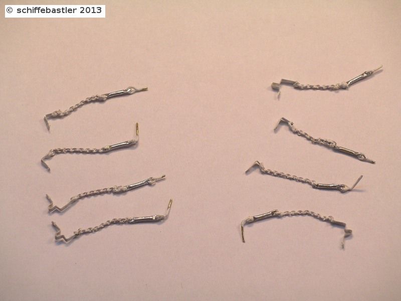
And now, the next preparations, a jig to serving ropes.Due to the fact, that the Americo Vespucci contains steel shrouds I need a jig to serving these ropes. I took the plans from Jürgen Nicklis, but enlarged it a bit. It can be used manually or by adapting a drill machine.
 Here you can see some examples. In the middle the basic rope which was build of three strands. It has a diameter or 0,8 mm. The upper rope was produced by using a drill machine, the handling is not easy and the result is not good enough. The lower rope is build with manual usage of this jig. It is much better to control and it looks better. But still it needs some practice.
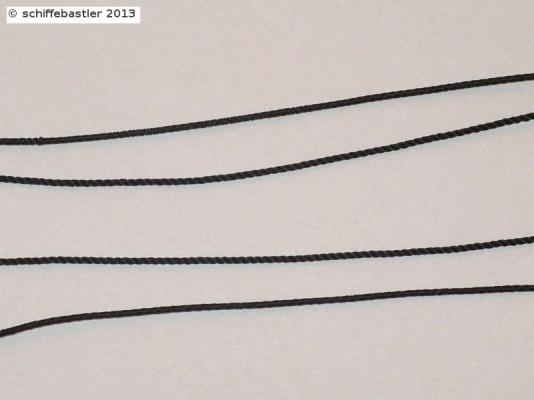 Bye, Joachim
- dafi and popeye the sailor
-
2
-
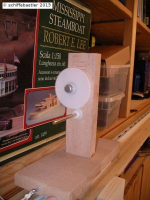
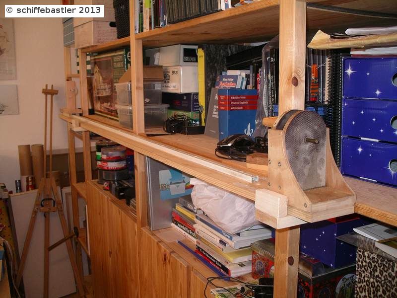
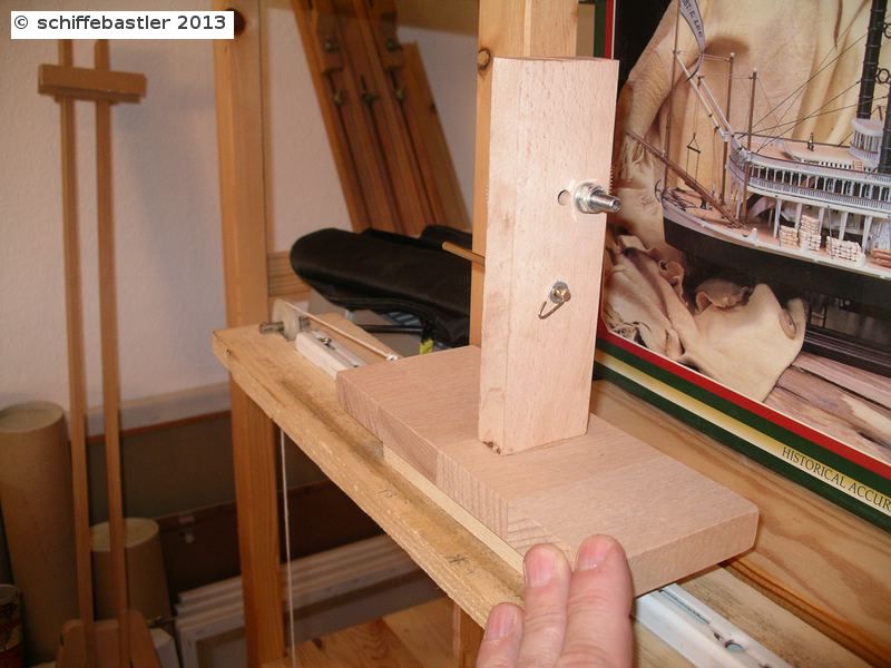
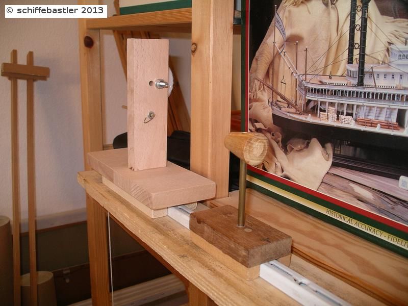
Hello everybody,now a continuation of the Amerigo. The last few weeks I made some tests concerning rigging and I finalised the calculation of thickness of the ropes. For doing this, I based on the lists and calculation rules from Wolfram zu Mondfeld within his book "Historische Schiffsmodelle".First of all I build a rope walk for producing own rops according to the needs.Here you can see the rope walk, fixed on a shelf.


 And as you can see, the fist results are ready for waste...
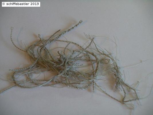 At the end I succeeded with some examples of the major type ofropes, needed for the Amerigo.
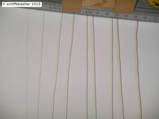 Bye, Joachim
- dafi and popeye the sailor
-
2
-
Hi Michael,
I love your courage for modifications, and you are always right doing this!
Hope after Christmas I will have a bit more time for my own build log.
Now, I wish you a Merry Christmas, Michael
Regards, Joachim
-
Hi Michael,
congratulations to your new machine! I am sure, after some attempts with it, you will realize wonderful results.
Concerning rigging, I see no major problems for you. In the past you showed us so much skill, therefore I am sure, you will also solve the rigging perfectely.
Bye Joachim
-
Many thanks Grant! So, step by step I will always learn a bit more .
Bye Joachim
-
Hi Wacko,
thank you for your interest. And of course I like to show you some details.
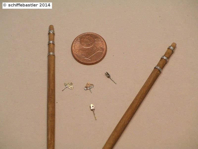
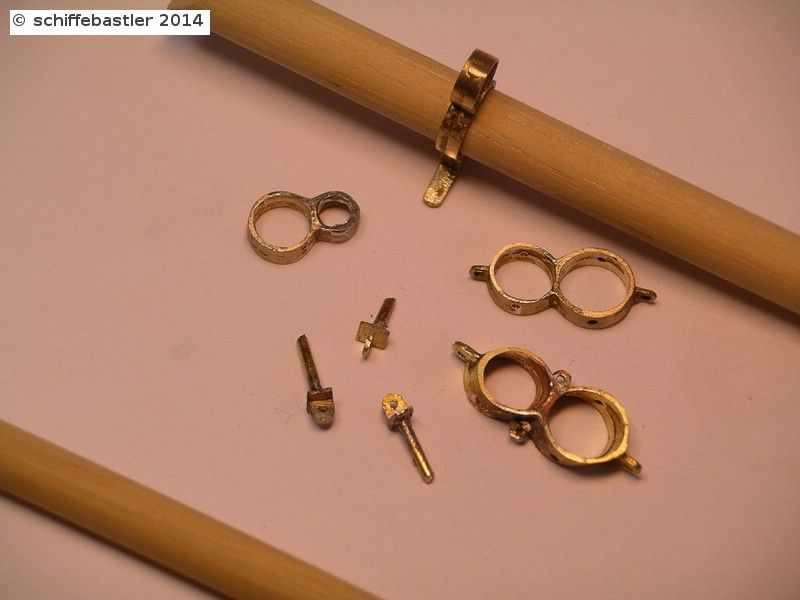
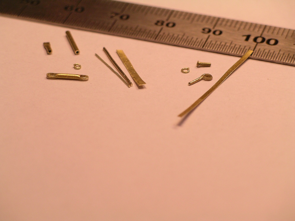
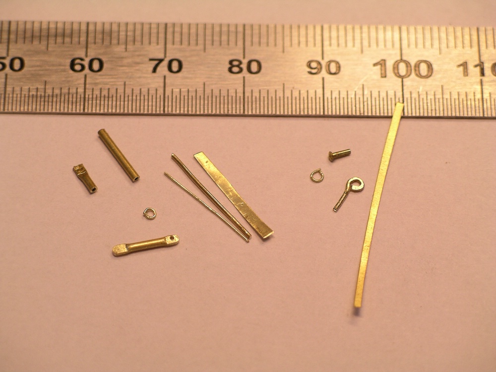
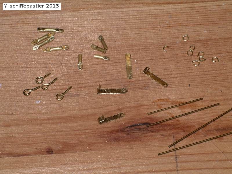
On the enclosed pictures you can see some spare parts, on the left the basic parts of the lashings and on the right some of the basic parts of the fittings for the spares.
I used brass plates with a thickness of 0.1mm and cut strips of it with a width of 1 to 1.2 mm, depending on the needs.
The clamping screws I build of small brass tubes with an outher diameter of 1mm and an inner diameter of 0.5mm. After cutting parts with a length between 5 and 8 mm (depending on the type), I could easyly press the end of the parts, hone down it and drill a hole (0.5 mm) in it. The connection of the parts of the clamping screws is build with 0.5 mm wire. The connection of the parts is done with rings of 0.3 mm wire, wich I had to build.
Similar material is used for the fittings of the spares. The connection is build of small rings which have been honed a bit and connected with small parts of nails.

Hope, my description is not too confusing and my english is not too bad, but unfortunately I made no photo while assembling the parts.
Bye, Joachim
- dafi and popeye the sailor
-
2
-
You are so kind Michael, thank you very much for your compliments!
Bye, Joachim
-
Thank you very much Wacko!
Will continue soon, but actually the Amerigo is displayed on a German model ship fair. Next week I will come back and continue.
Bye, Joachim
-
Very nice, it is going on! Looks really good
Bye, Joachim
-
And now the last update for today.
These are the last parts before finally starting with the rig.
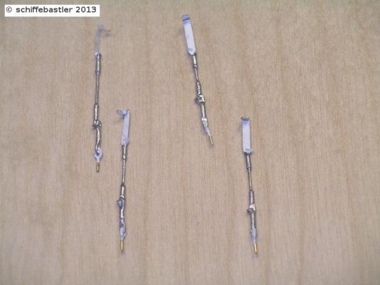
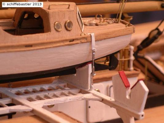
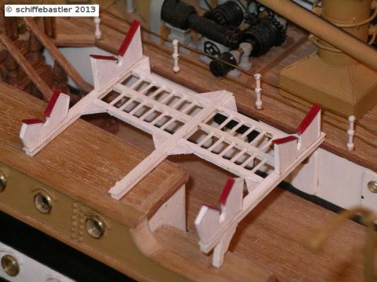
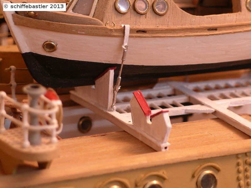
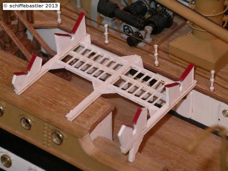
On each front side of the ship there is fixed one spare (sorry, don't know the right english word ...). These are fixed with a head fitting and can swing outside. They are used to attach the boats whenever the ship lays on road and the boats have been launched.
In this case a handrail is fixed on top of the spare and the ladders are fixed. Then it is possible to go into the boats via the leashes or the ladders. You can see this on this picture.
Also this video shows, how it is used (after 40seconds video).
But the spares are also used in order to fix the studding sails, which you can see on this picture.
Now, how I made these parts.
Fixed on the ship

here you can see the head fitting
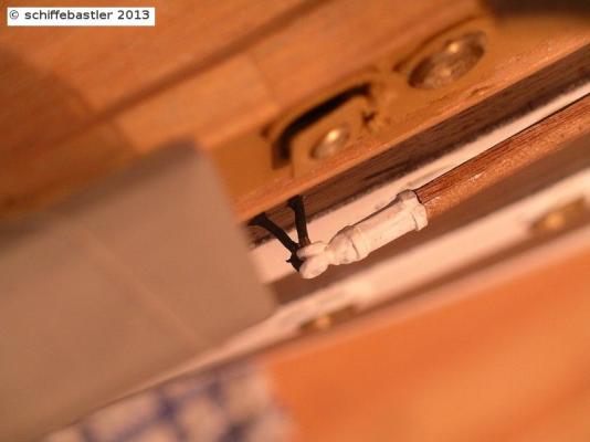
on the back the spare is fixed at the side of the ship with a special fitting, which can be opened.

And again a picture of the whole spare
Bye, Joachim
- Mirabell61, popeye the sailor and dafi
-
3
-
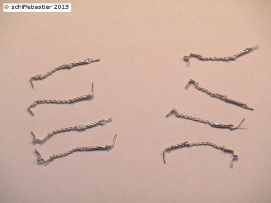
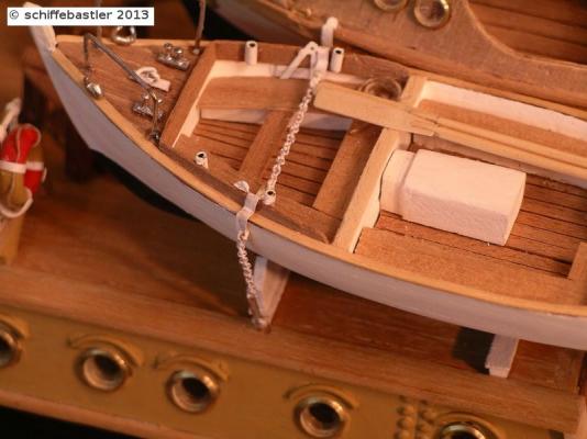
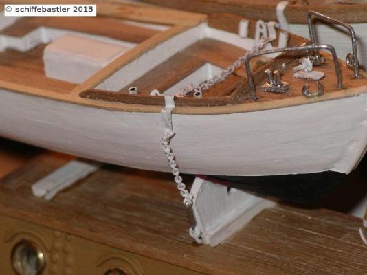
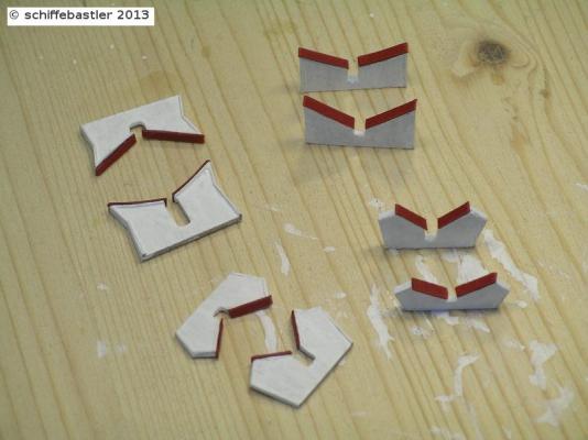
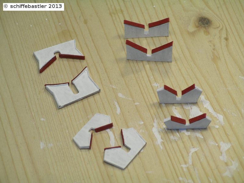
and now again some lashings for the open boats, which are build very similar to the others but contains chains and are also tightened together with chaines.
All of the lashings have not been within the kit and had to be designed according to pictures of the ship.
First a picture which shows the size of the parts.

and now the lashings for the open boats
Bye, Joachim
- dafi, hexnut and popeye the sailor
-
3
-
After the boats had tested the clamps, the had to be removed again, because there have to be build individual lashings. They are build of metal strips and fixed on top of the boats. The lashings are tightened with clamping screws. The parts are really small, e.g the metal strips are 1.2mm wide.

Bye, Joachim
- popeye the sailor and dafi
-
2
-
Hello everybody,
the last post has been long, long time ago.... but it is going on now. Perhaps, somebody will find the way again to the Amerigo...
Now the last things, which have been made.
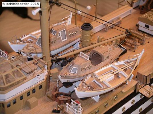
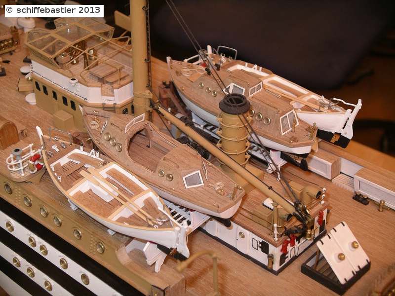
First of all the boatclamps. Again they are build according to pictures from the ship. They have to be fixed on the frames on deck. And then the boats test their clamps.

Bye, Joachim
-
Hi Michael,
I really love that pictures of the whole ship, it looks wonderful!
Regards, Joachim
-
Congratulations, Michael, there is no doubt about your decission to rebuild these parts, great result!! It looks also much more realistic, well done, I like it !
Regards, Joachim
-


Amerigo Vespucci 1931 by schiffebastler - Mantua - scale 1:84 - Italian sail training ship build
in - Kit build logs for subjects built from 1901 - Present Day
Posted · Edited by schiffebastler
lost pictures
Hello,
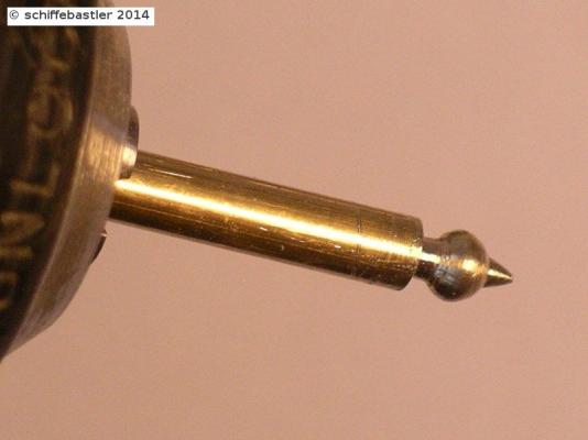
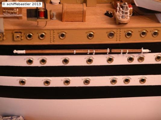
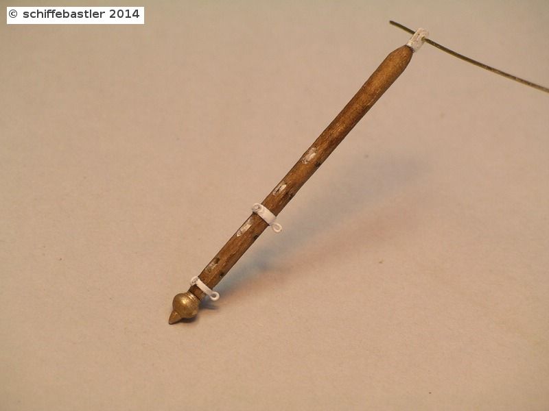
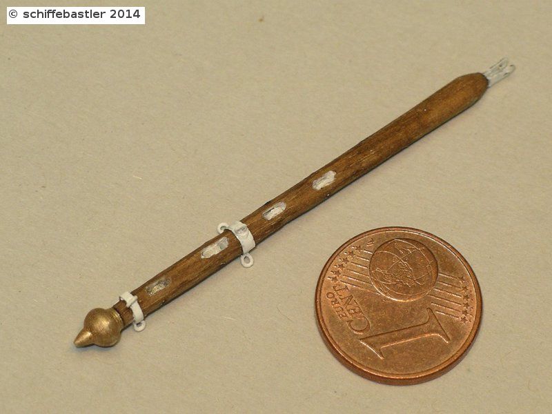
before assembling the bowsprit, I made the flagpole which will be fixed at the bowsprit.
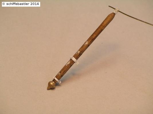
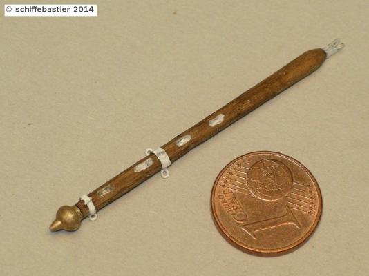
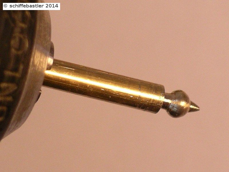
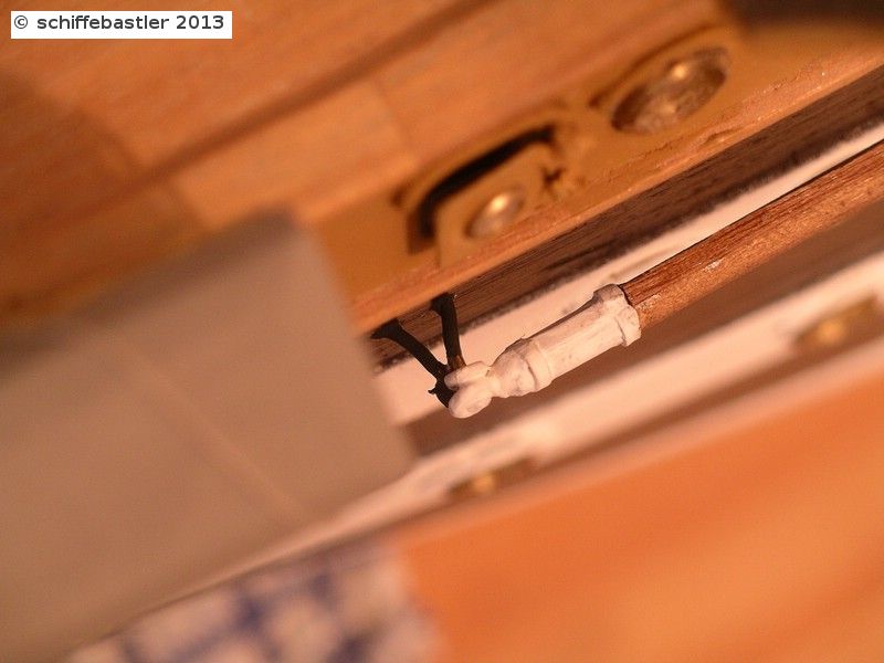
Through the head of the flagpole (1mm thick) I drilled a hole for the flagline and made a metal fitting on it. The head of the flagpole will get golden colour. At the lower part of the flagpole is soldered a cleat.
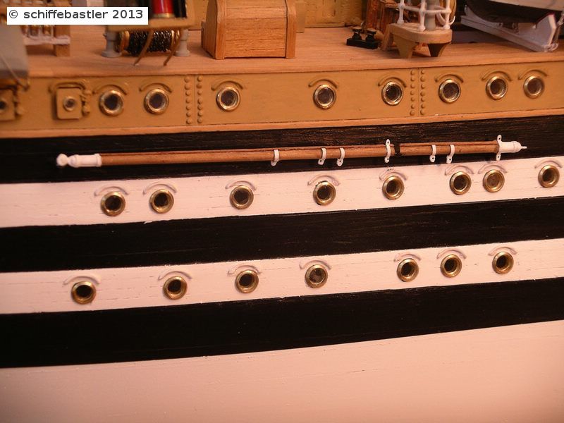
This is the final, coloured flagline, put on the bowsprit.
Regards, Joachim