HOLIDAY DONATION DRIVE - SUPPORT MSW - DO YOUR PART TO KEEP THIS GREAT FORUM GOING! (Only 20 donations so far - C'mon guys!)
×

SawdustDave
-
Posts
1,770 -
Joined
-
Last visited
Content Type
Profiles
Forums
Gallery
Events
Everything posted by SawdustDave
-
 Thanks Jon.... So glad to see you dropping in. You're right about the lids, and I gave it a lot of thought and decided to add them now, realizing I may have to re-glue a few of them that get bumped out of place while working around them. Actually,the lids are surprisingly sturdy the way I mounted them. The cutaway sections of the spar deck.... I can't tell you how many different configurations I went through in my mind and on paper. My personal favorite, of all the ships I have build over the years, is the Confederacy, which has a similar cutaway. I always wished the Captains quarters was more visible.... that is why I have left that area more open on my Connie. Just wish I could have come up with a way to leave those bilge pumps more visible. Cheers Dave
- 742 replies
-
- 7
-

-
- constitution
- frigate
- (and 1 more)
-
Beautiful work Tom. I am excited for you.... just to see your mast rigging coming together so nicely. Few people in the world could possibly understand the amount of time and precision crafting that goes into the rigging of a tall frigate. I am always as impressed as if I have never done one. Looking great! Dave
- 1,348 replies
-
- 3
-
-
- constitution
- model shipways
- (and 1 more)
-
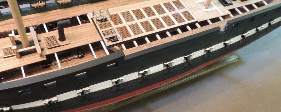
Gun Port Lids - Starboard side finished..... We can finally return to spar deck fixtures. After applying stain to the new decking, I expect I'll begin with fife rails before I take on that beautiful steering wheel....
- 742 replies
-
- 15
-
-
- constitution
- frigate
- (and 1 more)
-
Feel the same way about leaving the cut away Piet. Thanks for the visit. Dave
- 742 replies
-
- 4
-
-
- constitution
- frigate
- (and 1 more)
-
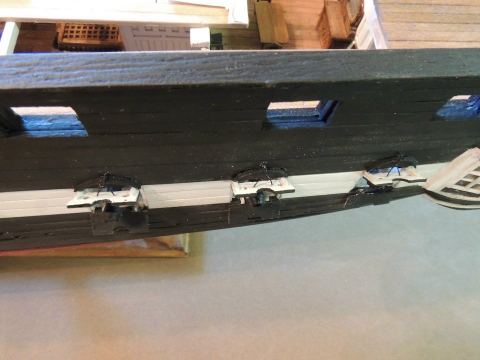
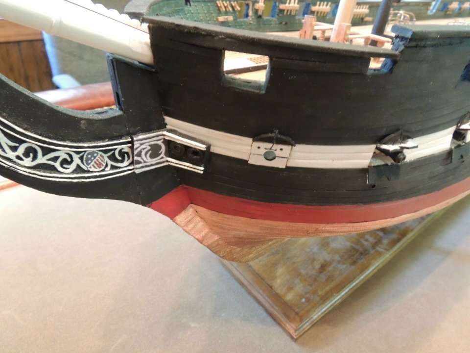
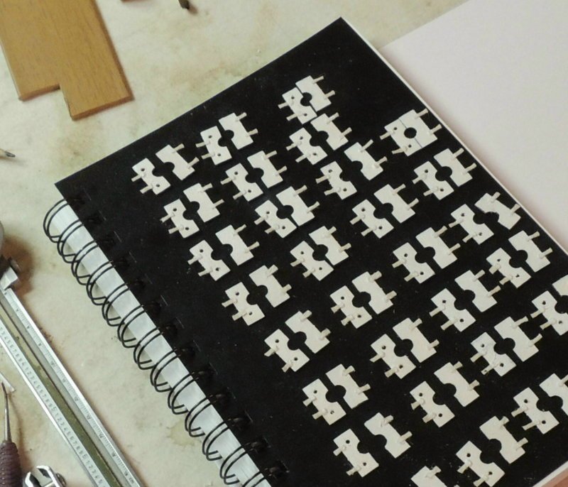
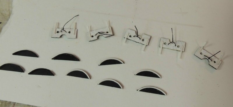
Gun port lids.... Man! After a dozen models over the years, this is the toughest gun port lids I've ever run across. Obviously, the split lids simply double the task. Not only the cutting and shaping and painting and hinging of both lids, but also drilling the two port holes in the top lids, and fitting the tricky split cords. Then, there's the little arched "carving" above each gun port opening (seen below)....
- 742 replies
-
- 10
-
-
- constitution
- frigate
- (and 1 more)
-
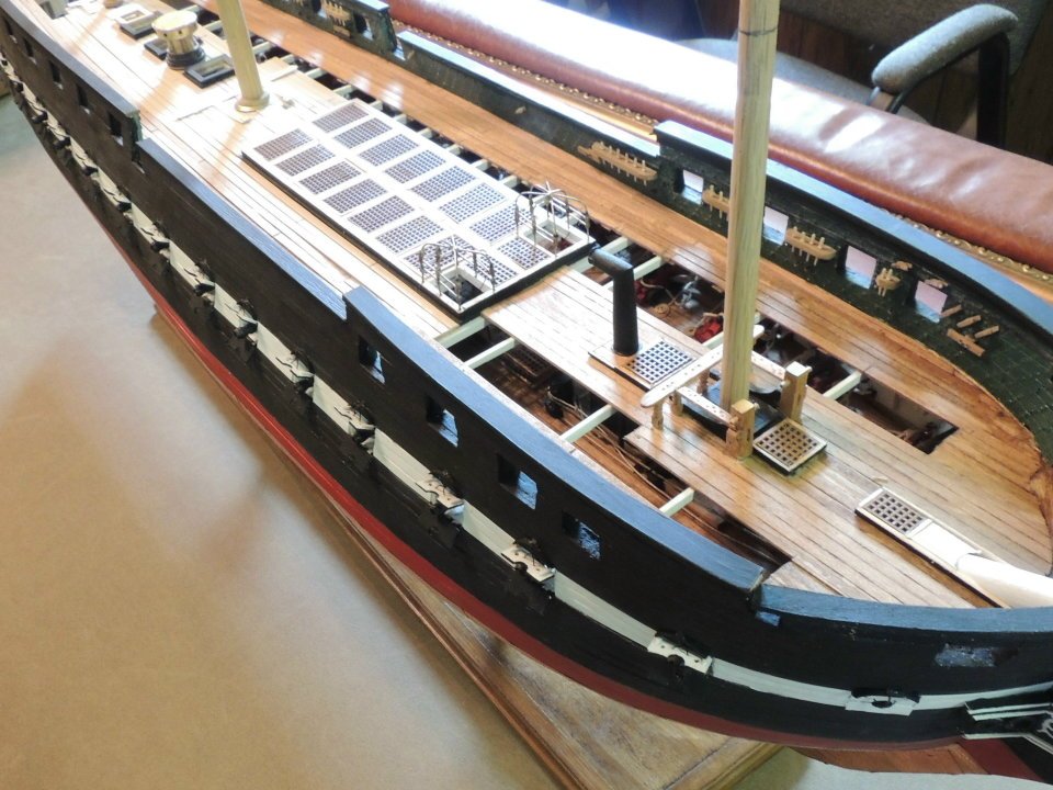
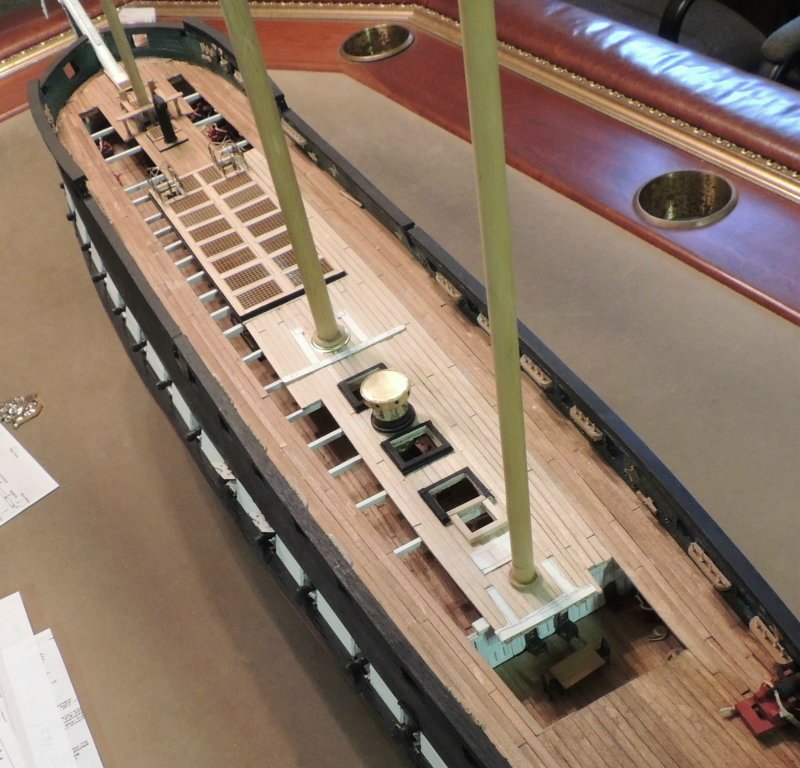
Back to work.... I did not realize it has been six weeks since my last posting. Time really flies when you're having fun. Reason being, my normal ship yard time has been disrupted with a fund raising project I've been working on for my favorite charity.... Hope For The Warriors. I did, however, manage to get in a few licks along the way.... The spar decking progress is now completed, with the port side cut-away allowing a view of the gun deck details.... also leaving the deck above the Captains great room completely cut away.... Note, I have not stained the new planking yet, and the masts are dry fitted at this point. Also note, the openings for the companionways have been rough cut and the fife rails are represented by paper templates. Long way to go........
- 742 replies
-
- 12
-
-
- constitution
- frigate
- (and 1 more)
-
YEA! The Dutchman is back on line! Great to finally hear from you Piet. Hope you've got the homestead all ship shape again my friend. Dave
- 742 replies
-
- 6
-
-
- constitution
- frigate
- (and 1 more)
-
Thanks Ken.... I do have a lathe, but have never used it for anything other than turning wood. I have have no tailstock chuck, which I would need in order to turn metal..... so I just placed an order for one with MicroMark. By the time I get around to those other three frames, I should be in business. Also Mark.... Thanks for the visit. Always a pleasure to hear from you Mate. Dave
- 742 replies
-
- 7
-
-
- constitution
- frigate
- (and 1 more)
-
Tom.... I must admit, after so many failed attempts, I was very tempted to scrap the idea of modeling the canvas frames with the same reasoning as you stated. But then Ken's work is so inspiring....I guess I'm just too stubborn to walk away from a good scrap, even when I'm getting my butt clobbered!
- 742 replies
-
- 6
-
-
- constitution
- frigate
- (and 1 more)
-
Canvas Frames Progress.... I don't really like to admit this, but at some point, we have to accept things and move on.... right? The brass canvas frames may be the most challenging tasks I have personally attempted in the ten years I've been hooked on tall ship modeling. I am saying this as a wood worker, having very limited experience soldering tiny brass parts together.... getting 32 connection points together without leaving a big blob of solder took a bit of trial and error and a lot of scrap pieces for me to develop a little bit of technique.... not perfect, but they do pass the 36" test. Back to work on developing the Spar deck. It has been almost a month since I have made a single grain of sawdust!
- 742 replies
-
- 12
-
-
- constitution
- frigate
- (and 1 more)
-
Great to hear all's well with you guys Piet. Thanks for the report. Dave
-
Report? How did Palm Coast fair? How are you and Gwen? Anxious to hear from you this morning Piet.
-
Great to hear from you Piet. As I figured, you've got your home engineered to stand up to about anything Irma will throw at it.... short of devastating storm surge, which I assume will not likely hit you on the eastern coast according to her westerly tracking. Then the numerous "twisters" that spin off from these things are another major concern. (that's what got us in Louisiana when Rita ripped up my little factory) So....We're gonna be worried like a mother hen for you and Gwen 'til this thing is over. Stay safe old man. Dave
-
Thank you Carl. Can't help but worry about our friend. As much as I trust his judgement, there are things like a Cat 4 or 5 monster hurricane you just do not challenge. please advise if you hear from him. Dave
-
Where are you and Gwen old man? Hope you got the heck out of there!
-
Wish I wasn't totally strapped to my Connie build right now. Would dearly love to build this one along with you Chuck. So I'll take a front row seat and learn. Dave
- 1,784 replies
-
- 5
-
-
- winchelsea
- Syren Ship Model Company
- (and 1 more)
-
Thanks Piet.... And knowing you as well, you would have knocked this one out of the park on the first pitch. Actually, the reason I'm fretting so over these first two frames is 'cuz there's three more companionways and the skylight once I get past the main hatch area. Using soft solder and a mini butane torch. Getting there, slowly but surely mate. Of course, if you want to take another road trip up my way, I'll save this little task for the master. Personally, I would dearly love to be building the first of several launches right now. Cheers
- 742 replies
-
- 5
-
-
- constitution
- frigate
- (and 1 more)
-
Still not happy with the brass frames. Stay tuned mates.
- 742 replies
-
- 4
-
-
- constitution
- frigate
- (and 1 more)
-
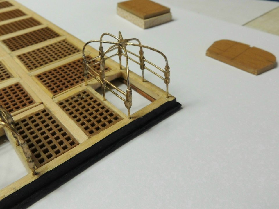
RE-DOING THE CANVAS FRAMES.... Due to a fund raiser project I've become deeply involved in, I haven't been able to focus a lot of time in the shop since my last posting. Unless I manage to get some help, this might be the case for the next several weeks. For the couple of early morning hours I do have, here's a short progress photo.... Wasn't real happy with the first attempt at creating canopy frames seen in my last post.... so I did what we all do.... tear it out and do it over. Other than the improved assembly technique, the biggest, and perhaps only notable difference would be the shaping of the top joint blocks which now have an upper bead turned into them. Secondly, since I'm definitely not much of a metal worker, it took a little practice and a lot of wasted brass rods to develop the technique for soldering the frame stanchions where they come together in the center of the module. Seen here, I've not added the little ball to the top nor painted over the solder.

- 742 replies
-
- 14
-
-
- constitution
- frigate
- (and 1 more)
-
Cutty Sark by NenadM
SawdustDave replied to NenadM's topic in - Build logs for subjects built 1851 - 1900
Amazing photo's Nenad. Thanks for sharing. Dave- 4,152 replies
-
- 8
-
-
- cutty sark
- tehnodidakta
- (and 1 more)
-
Congratulations Ken, and thanks again for providing this amazing tutorial log.... especially for those of us who will be using it as a resource in our efforts to build this great war ship.
-
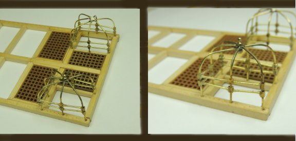
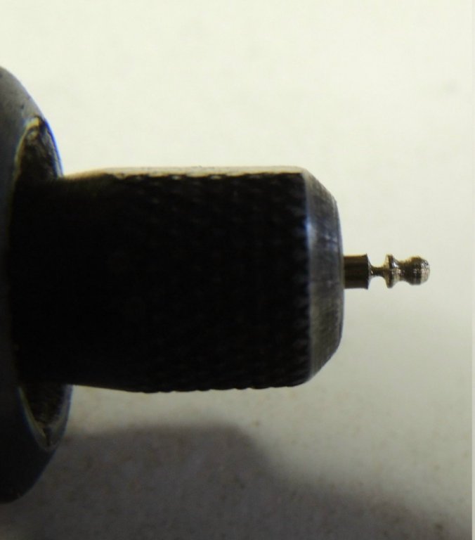
CANOPY FRAMES.... After some frustration with how brass canopy frames can be built without a milling machine, here's the best I can come up with mates. As noted in my previous post, the joints were absolute hair pulling, to say the least. Tried soldering.... failed. Tried CA.... not so good. Tried epoxy Jon.... not much better, mainly because of the long cure time. Then discovered the solution was actually in the method of assembly! After tacking all of the corner connecting blocks into their carefully measured position on the formed stanchions, I drilled out the stanchion holes in the coaming frame, Then inserted the stanchions into the appropriate holes with NO RAILS. I then soldered the center of the stanchion assembly, thus firming up the assembly. From there, the task of adding the rails became a matter of careful measurement and forcing them into the holes in the corner blocks. Although you will see some CA tacking in this photo, I'm not sure it was even necessary because the "spring tension" of the stanchion frame tends to hold the rails quite secure with no tacking except for the tiniest dab of CA on the tip of the rail as it is forced in place. Here's that little center top ball... shaped by spinning two Dremels (one with a diamond cutting wheel). I still have to polish the brass a little and paint the soldered joint with some brilliant gold metallic. I haven't decided if I will try to add a little foundation block at the foot of each stanchion. Playing around with that detail now. NOTE.... I will be taking a break from the shop this afternoon to go outside and watch the solar eclipse, as we are very close to the path of "totality".... yes, we do have our special glasses.
- 742 replies
-
- 12
-
-
- constitution
- frigate
- (and 1 more)
-
Thanks for the suggestion Jon. Had not considered epoxy glue. As for the tiny drill.... I sacrificed one of my Dremal bits with tiny burr tip. Had to grind the burr off and carefully grind the tip into a cutter point. So far I have only had to re-dress it once. Cheers
- 742 replies
-
- 5
-
-
- constitution
- frigate
- (and 1 more)
-
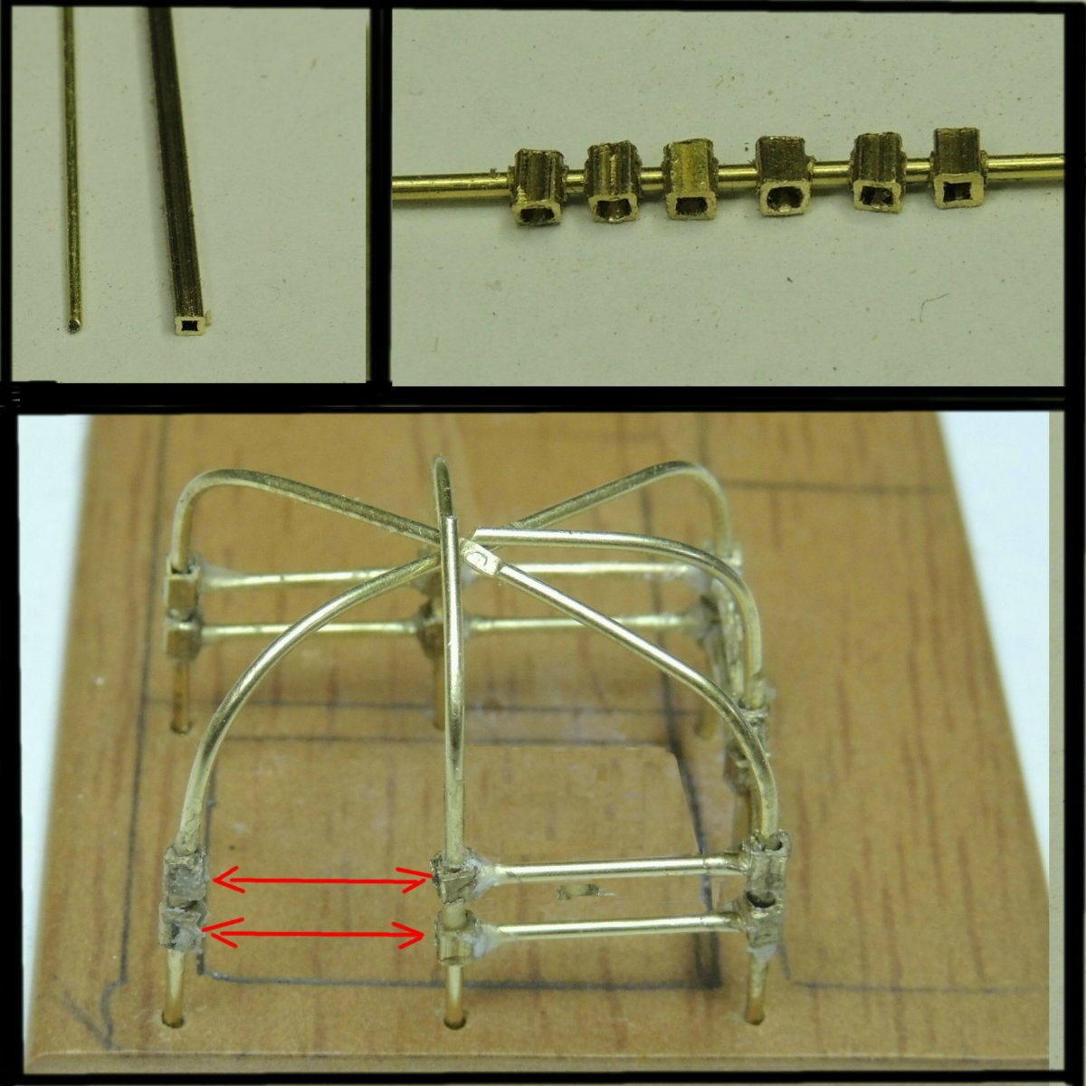
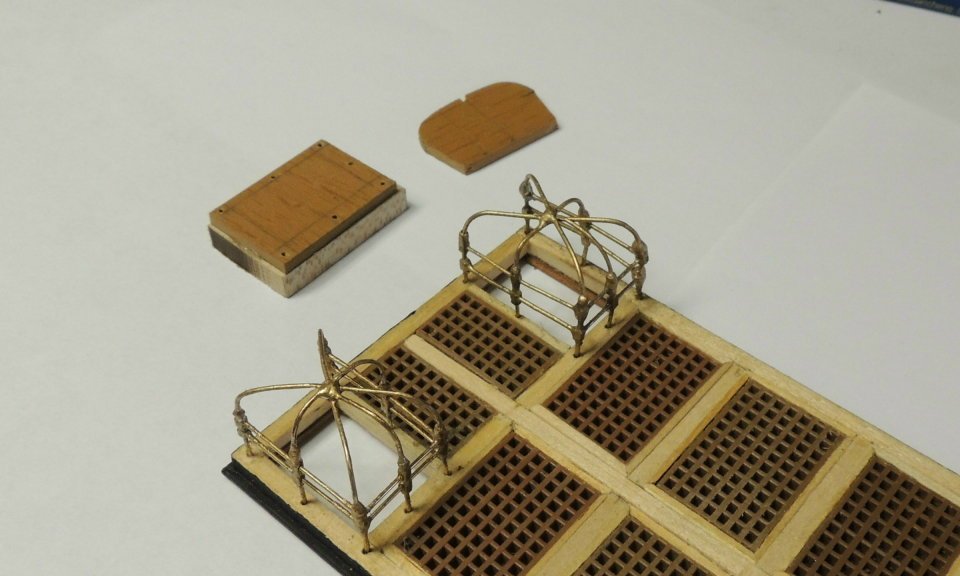
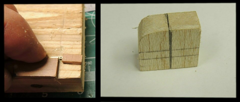
CANOPY FRAMES.... We all stand in awe of Ken's canopy frames. As much as I would love to immolate his method, without having the milling machine capability he used so beautifully , I simply cannot go there. So I have to attempt to tackle these canopy frames best as I can with what I have.... 0.032" brass rod and 0.058" square brass tube. Seen here, I have drilled out the connection blocks for the three center stanchions.... stowing them on a scrap rod. The corner connection blocks are drilled for the appropriate corner with single holes on the entrance corners, or two holes for the rear corners. The assembly seen here is in progress, with two more rails to be added as indicated by the red arrows. The platform is a assembly jig created to hold the stanchions in place and to insure the second module is precisely the same as the first. Note.... I created two other jigs that are obviously critical to this build. First.... The corner block cut-off jig is used to insure that each of the corner connection blocks are the exact same length. Second....The stanchion forming block used to shape the arc of each stanchion and also marked for the precise height location of each connection block. As much as I would have preferred soldered joints, I simply do not have the soldering skill to make 24 perfect soldered joints without having a big blob occur at some point and create a complete mess. After several hours of attempting to solder the joints.... destroying at least a dozen corner blocks.... pulling out hand fulls of gray hair I can ill afford to lose.... I reluctantly gave up! So I am now looking at one of several "liquid solder" solutions. Any suggestions? I do plan to solder the top center connection where the five brass rods come together. The CA glued joints in the above assembly will be touched up with brilliant gold metallic paint.

- 742 replies
-
- 7
-
-
- constitution
- frigate
- (and 1 more)