HOLIDAY DONATION DRIVE - SUPPORT MSW - DO YOUR PART TO KEEP THIS GREAT FORUM GOING! (Only 24 donations so far out of 49,000 members - C'mon guys!)
×

nikbud
-
Posts
203 -
Joined
-
Last visited
Content Type
Profiles
Forums
Gallery
Events
Everything posted by nikbud
-
 Lovely neat work, you never fail to impress!
 -
Thank you Katsumoto. I was convinced over a walnut keel from your build. I was initially debating wether to have the keel in a lighter wood like on my Virginia build, but seeing how good it looked on your build helped me decide - it also fits in with the story that the ship was built from a single log of "wizardwood". Cheers, Paul
-
Lovely work, I really like the look of the walnut hull planking.
-
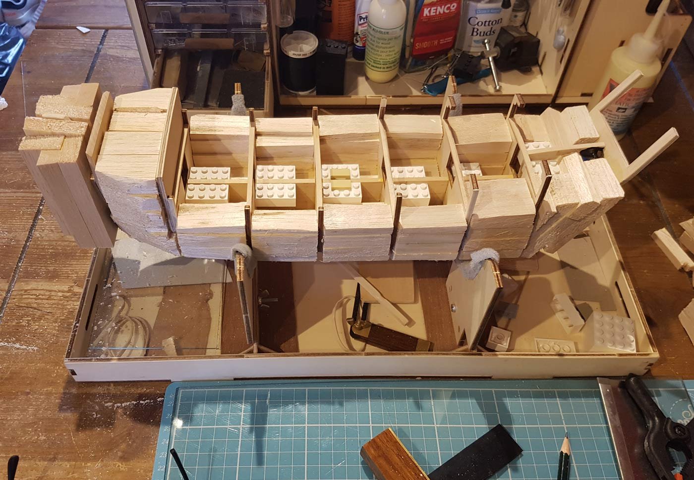
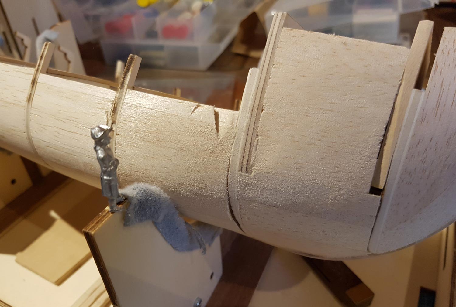
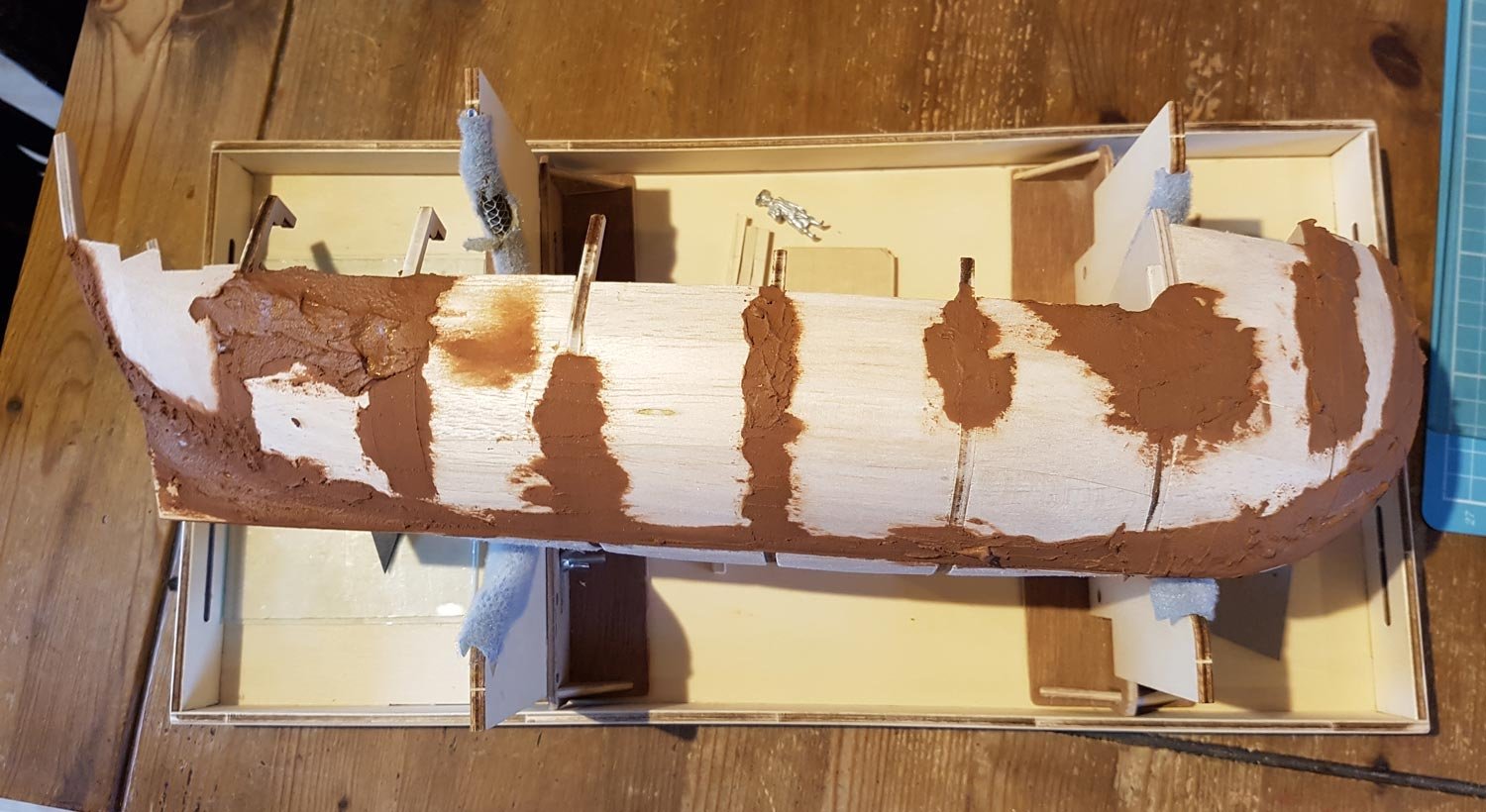
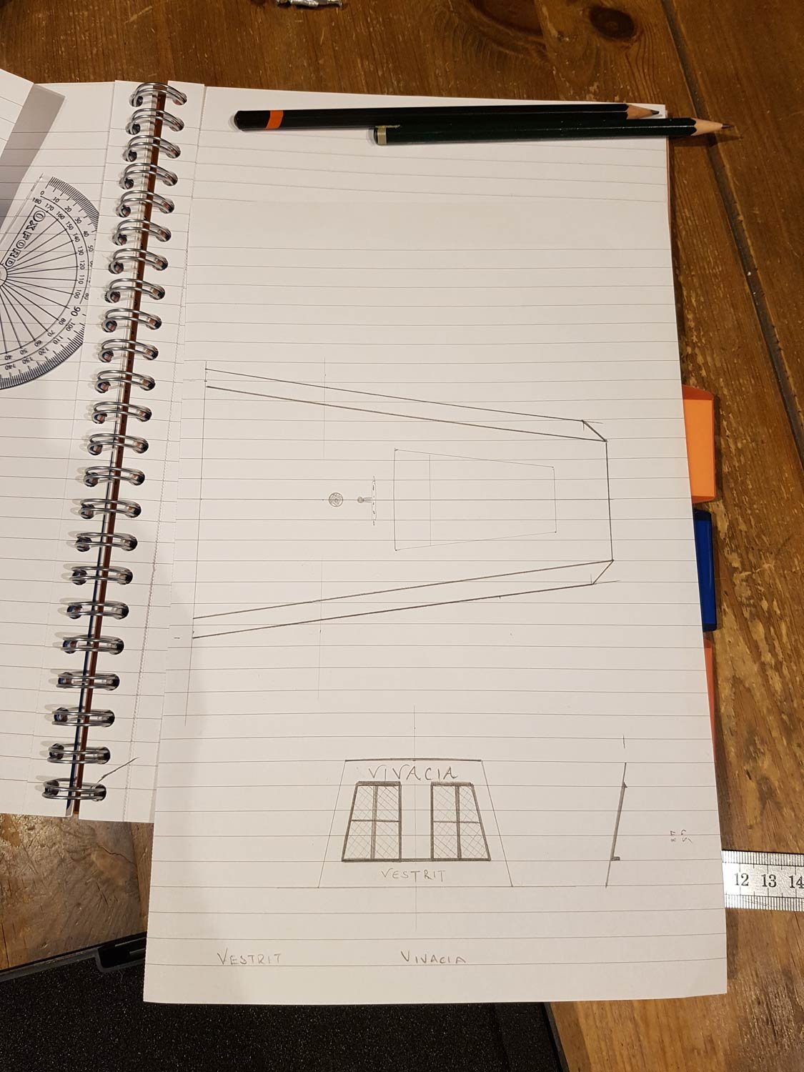
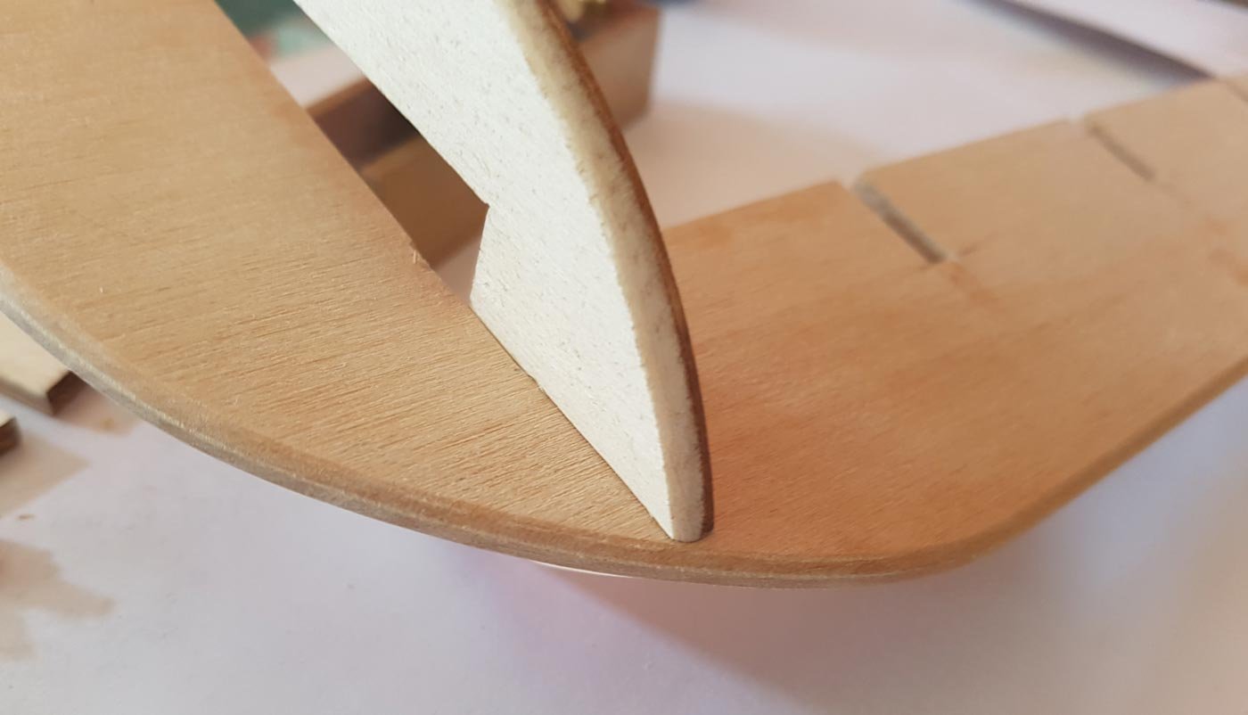
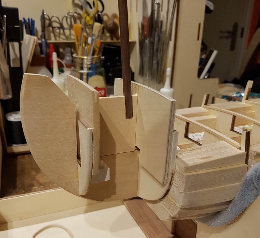
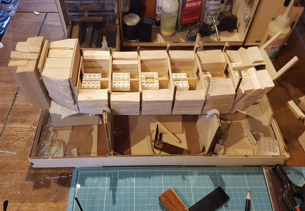
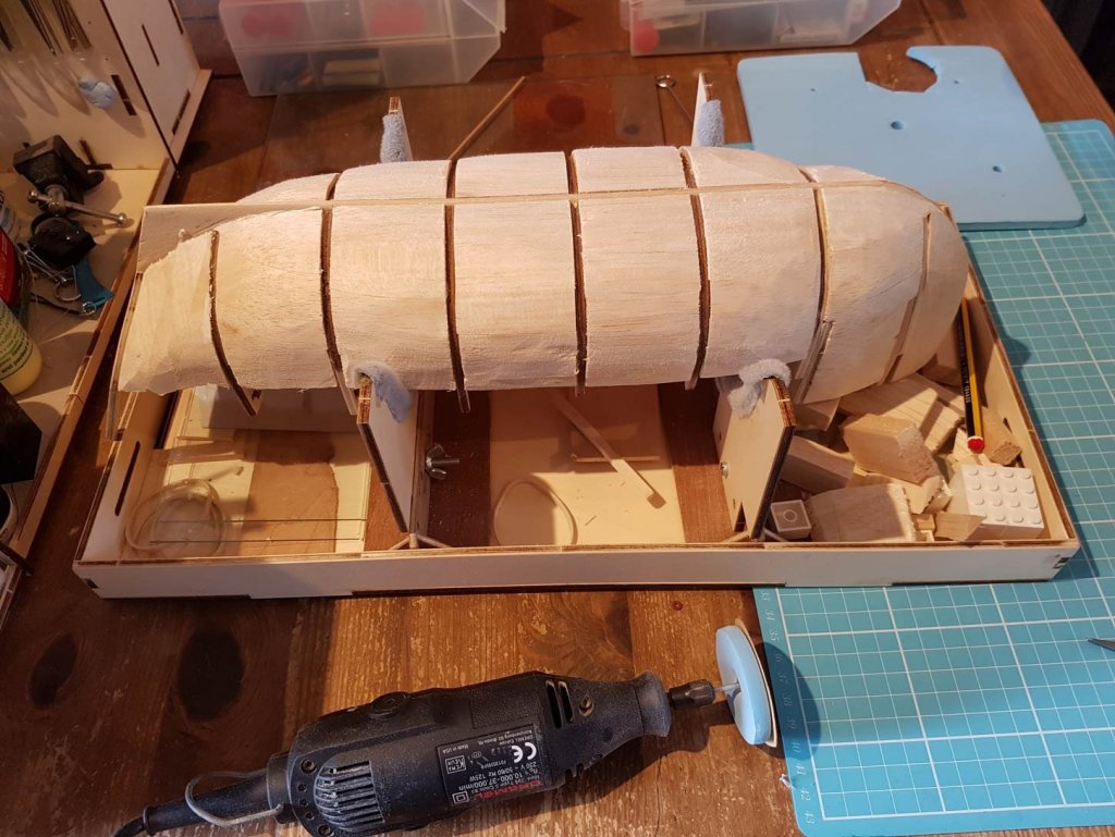
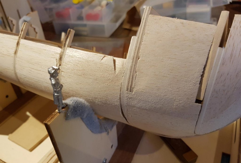
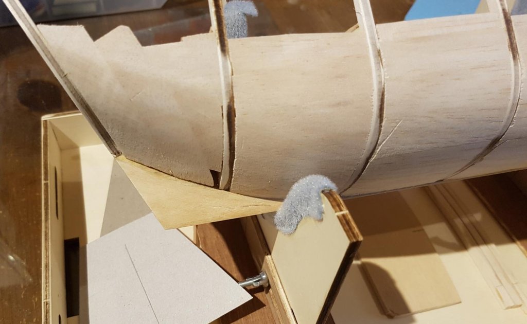
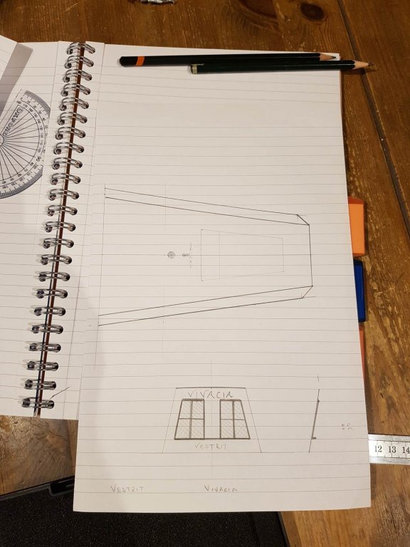
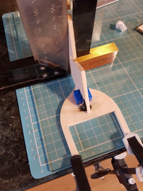
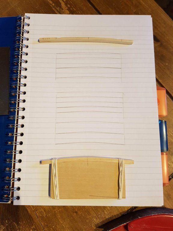
Hi all, not much has been happening in the shipyard the last couple of weeks, I have done a fair bit of thinking, changed my mind half a dozen times, and nearly threw the whole lot in the bin at one point! I think that the biggest mistake I have made up to this point is that I started building far too early. I should have spent much more time making accurate drawings of what I wanted to achieve. In part this is down to my flaw of rushing things. I really need to slow myself down and enjoy what I am doing rather than having an eye on what I want to do next, I always seem to want to hurry up an complete this bit so I can start the next bit. I am going to have to force myself to SLOW DOWN!! Anyway enough of my rant, onto the build; I fashioned a piece to hold the foremast and inserted it between bulkheads 1 and 2. I made it at an angle of 5 degrees from the vertical. I filled the hull with balsa blocks.. ..and did some initial sanding with the dremel; After some hand sanding the Captain helpfully pointed out where I had been over zealous; The transition between the false keel and the hull needs some work, at the moment it is too sharp, It will need some filler, in fact there are one or two places on the hull that need a bit… After many measurements and much thinking I have decided to build the aftercastle off the hull. The tumblehome will be 10 degrees. I will build a framework out of 5x5mm stock so I made an initial drawing of the expected size. I will use this to make a detailed drawing of the framework Like I said not much work, but I am trying now to take my time. I’m going to be making more detailed drawings so I can hopefully avoid some of the mistakes I have made so far and to enable me to be more accurate…….. See you next time…

-
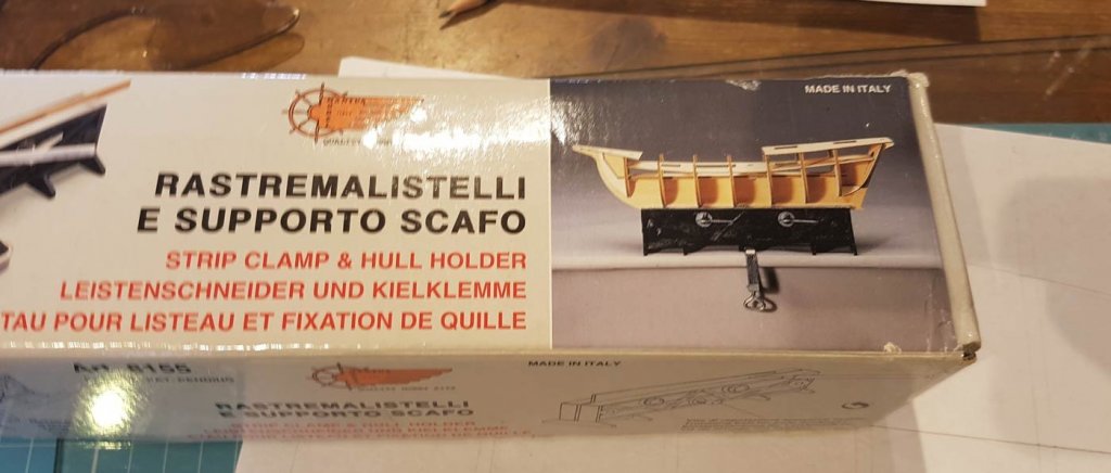
Thanks for the kind words Mark, although despite my meticulous planning I had a bit of a disaster today. I had cut out the space for the stern windows in bulkhead 8 painted the tiller cutout and pleased that things were going well, I glued the bulkhead to the false keel ensuring all was straight; Only when the glue was dry and a couple of other bulkheads had been glued on did I notice that the false keel had developed a slight warp between bulkheads 7 and 8. Initially I had thought that bulkhead 8 wasn’t glued on straight so I had tried to remove it but the CA and aliphatic glue wouldn’t loosen up at all. Eventually I realised that the keel itself was warped; it took a fair bit of soaking, clamping and heating to get the keel looking ok-ish. It’s not perfect but I’m worried that if I fiddle about too much I’ll create a worse problem. Luckily bulkhead 8 won’t be seen as the cabin area will stretch further aft and any slight wonkiness will hopefully be sanded out when I prepare the “solid” hull. As you can imagine I was a bit gutted and didn’t take any pics while I was trying to fix the warp but the Captain did come out to confirm that I had all the bulkheads glued up at last…… I did end the day on a little bit of a brighter note, I noticed on the box for the plank/keel clamp that I had bought 4 years ago that there is a picture of the Pinta. Just one of those coincidences that make life a bit more interesting. Hopefully I’m going to get time to order the wood for the keel, wales and upper planking this week. After seeing Katsumoto’s build log of the Santa Maria I’m going to make the keel from Walnut - the same as the kit planking. It also fits in with the books description that the keel, frames and hull planking was made from one “log”. Thanks again for all the comments and likes guys, they are always appreciated Cheers, Paul

-
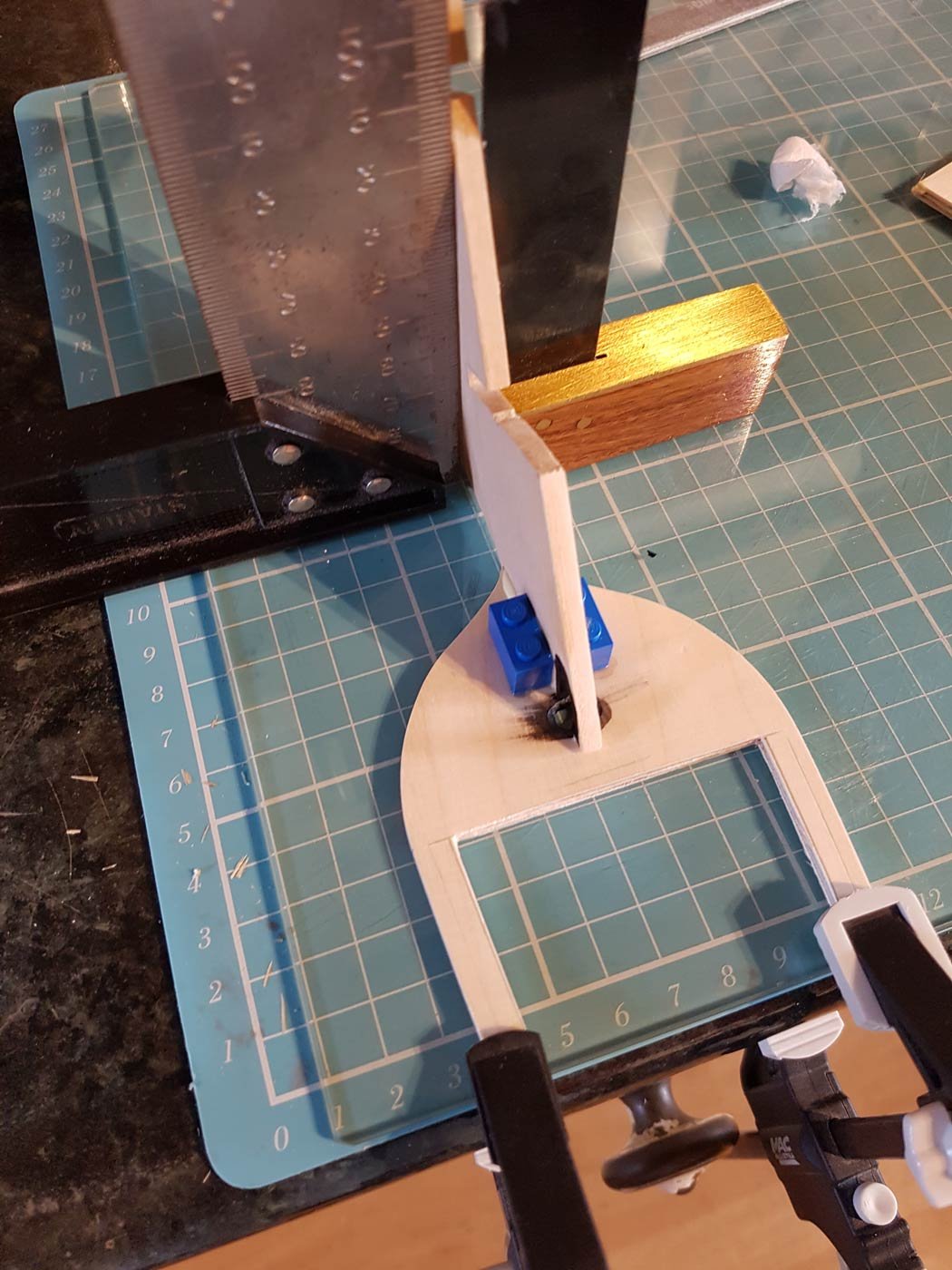
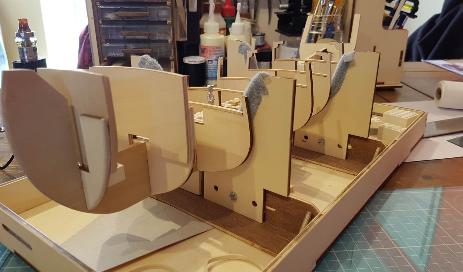
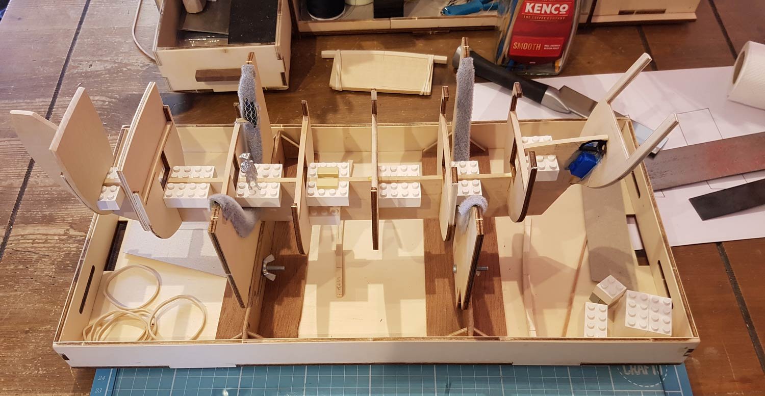
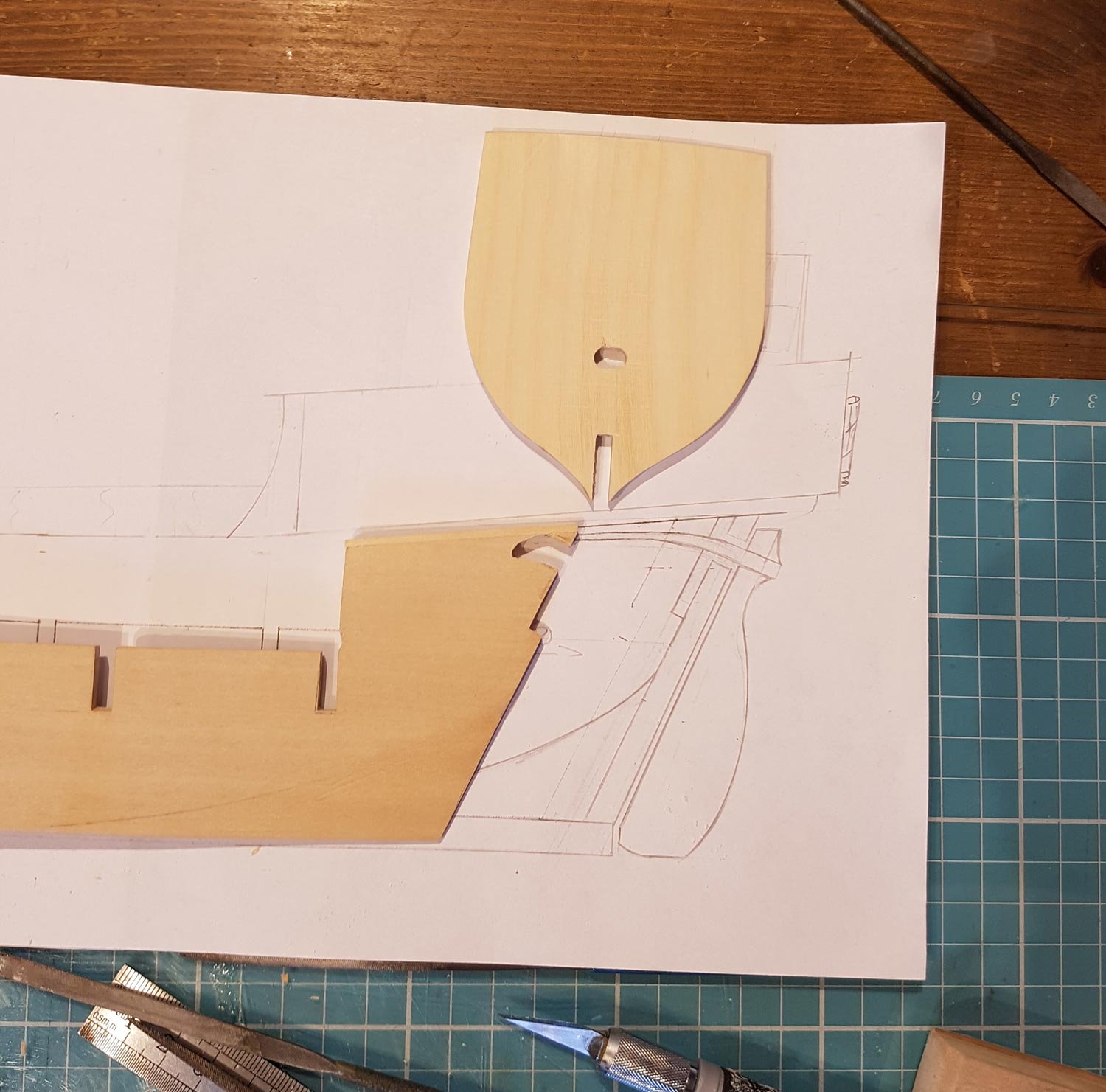
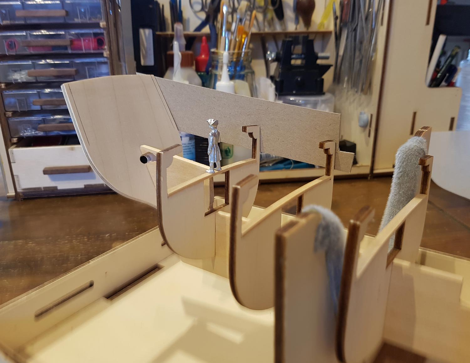
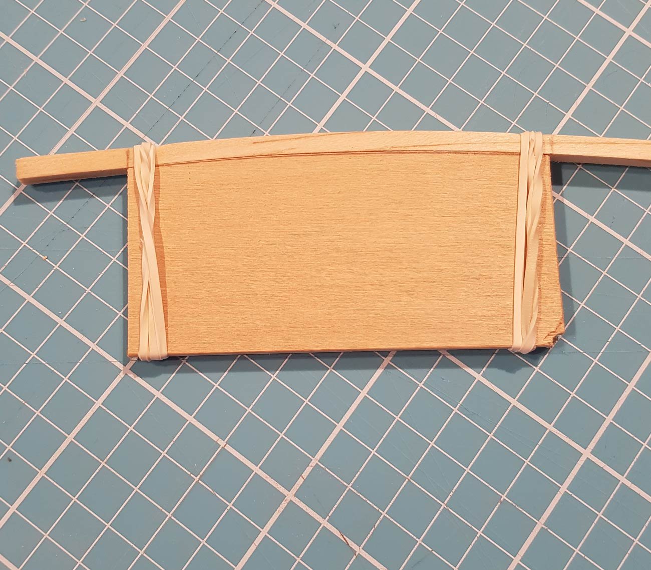
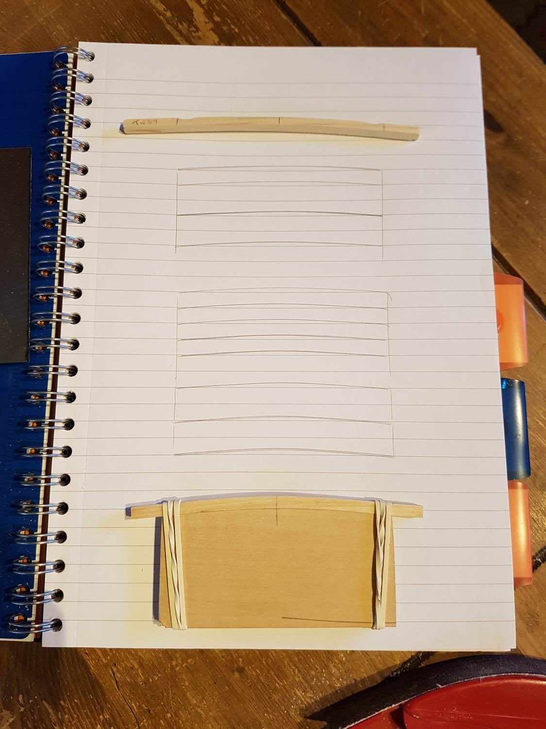
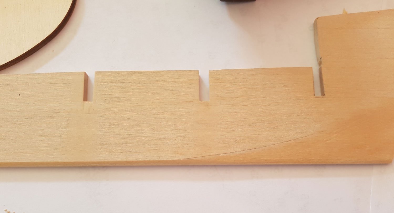
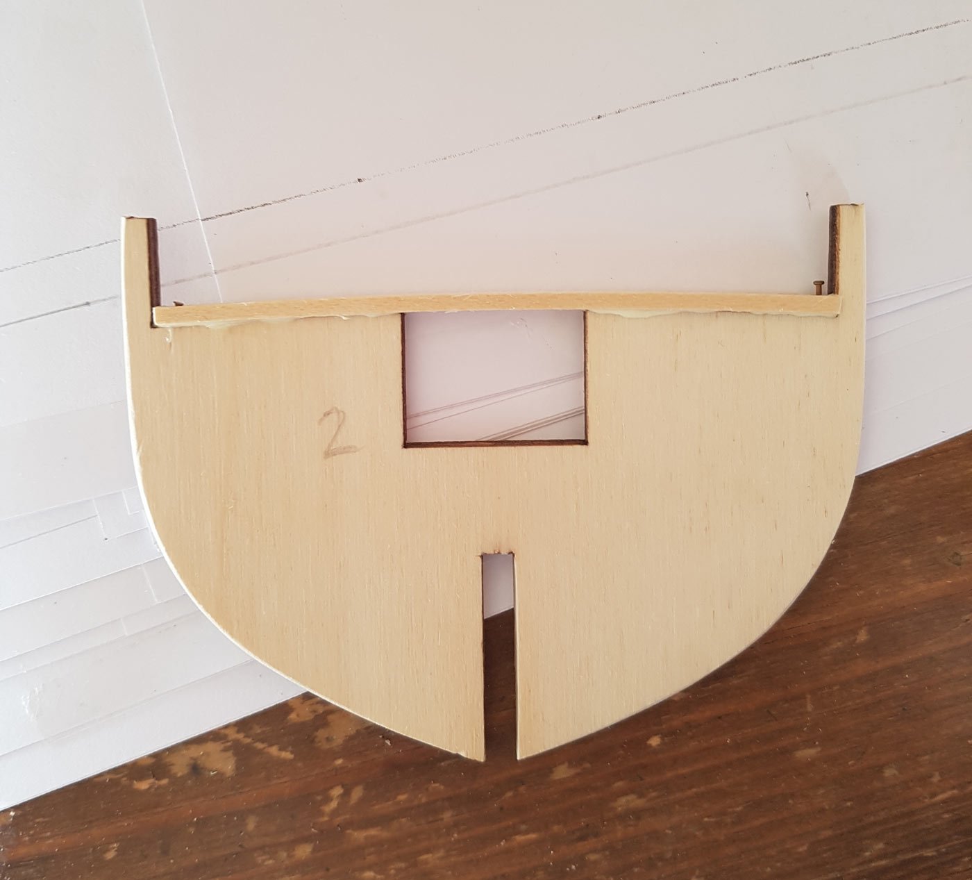
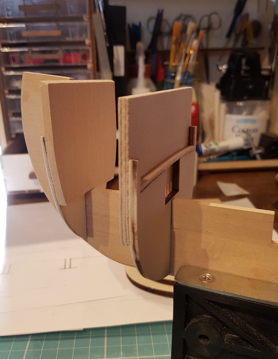
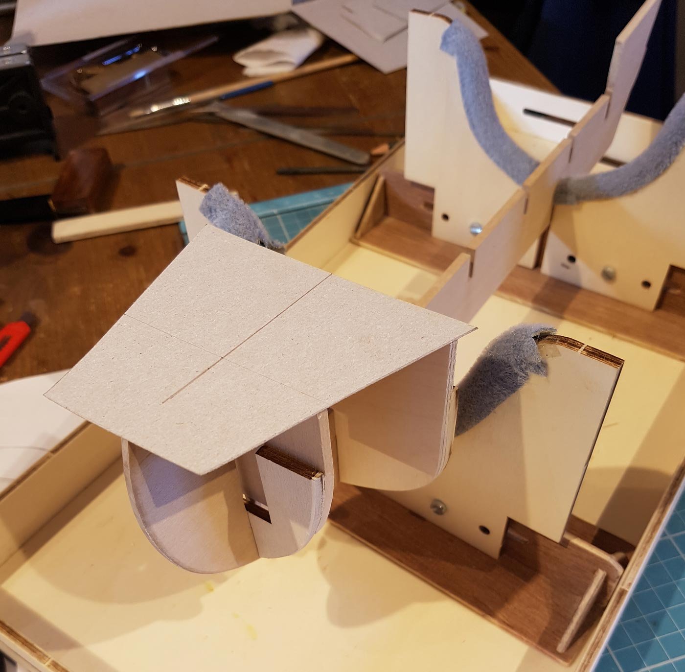
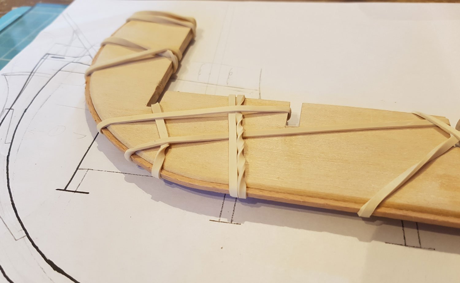
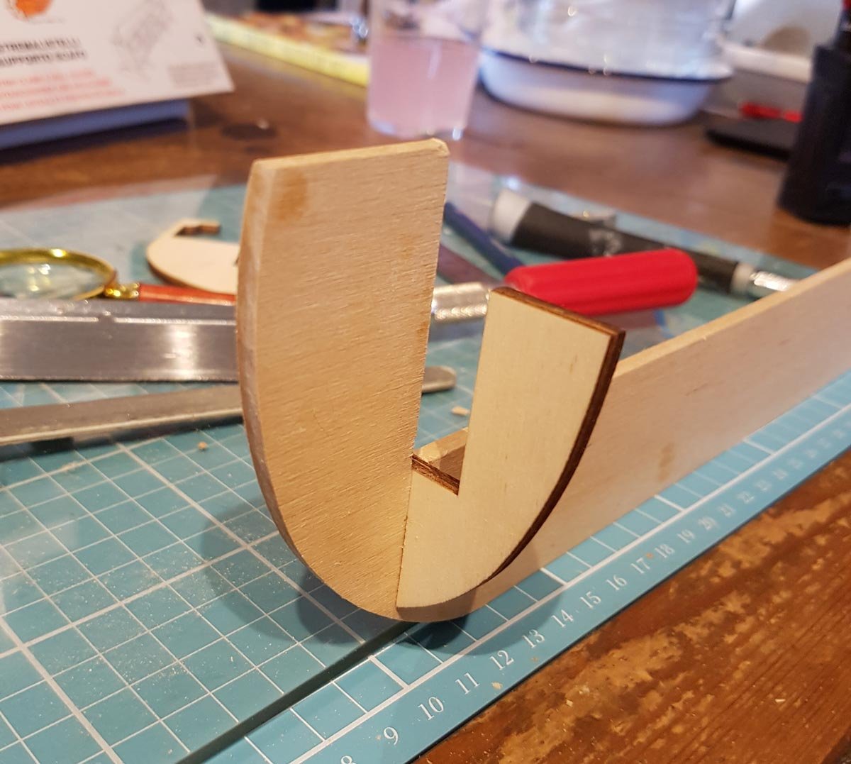
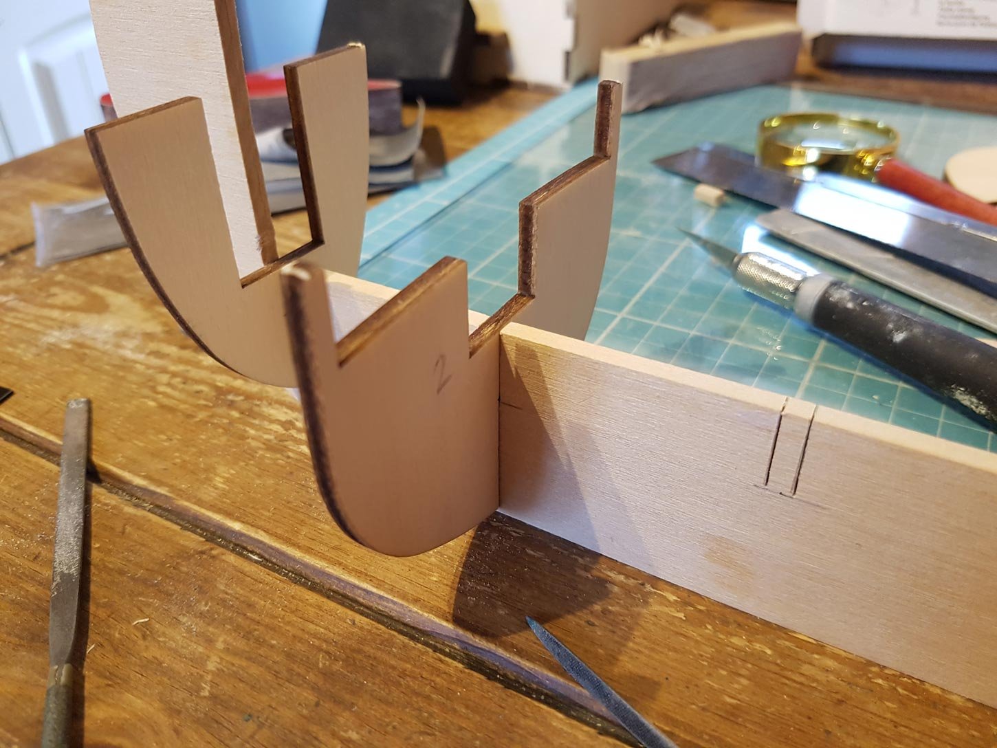
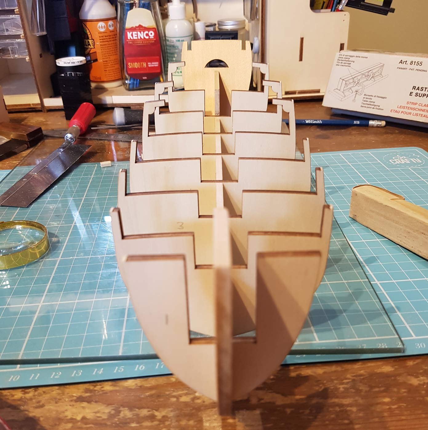
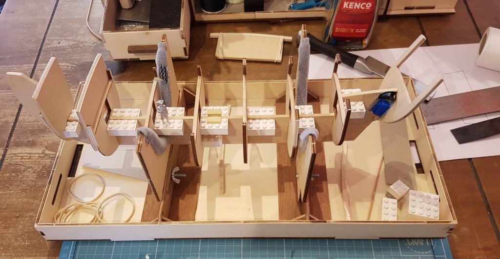
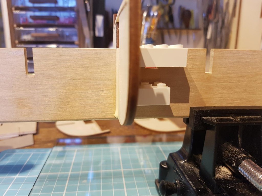
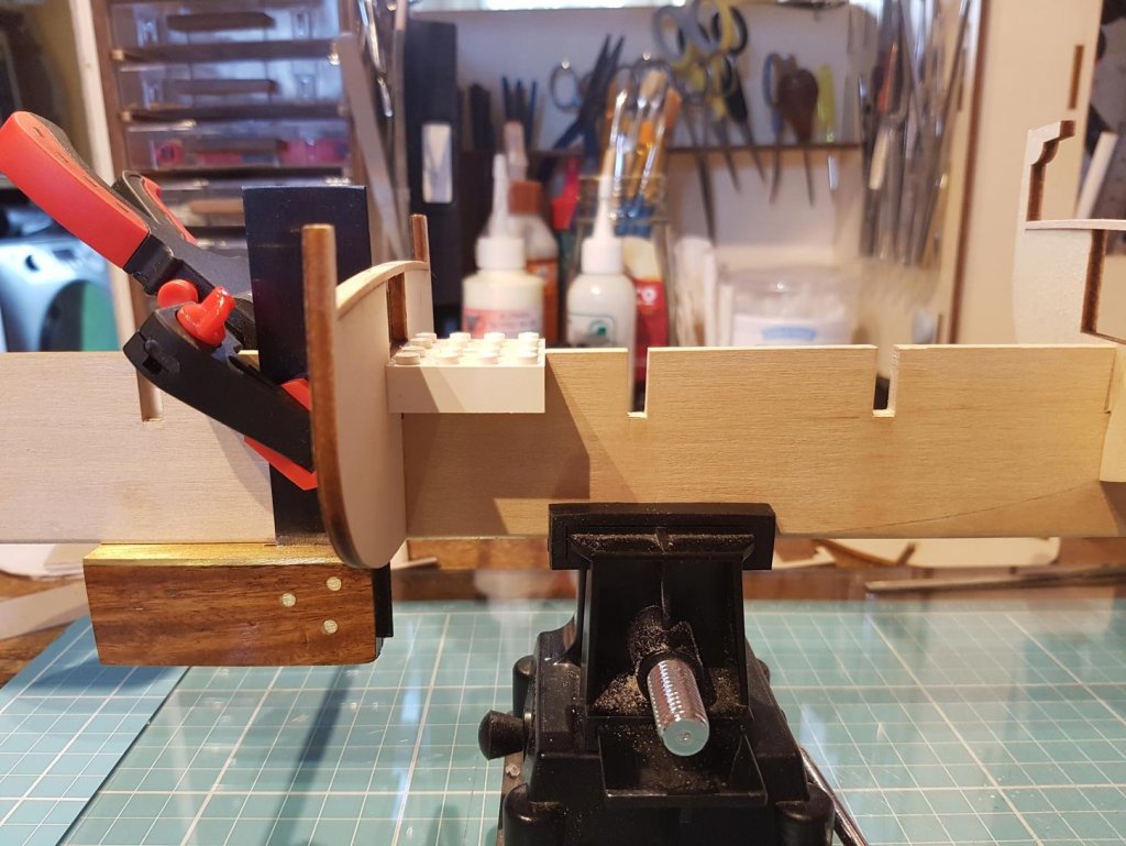
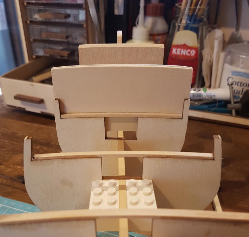
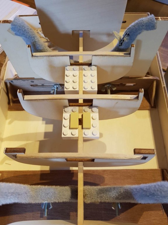
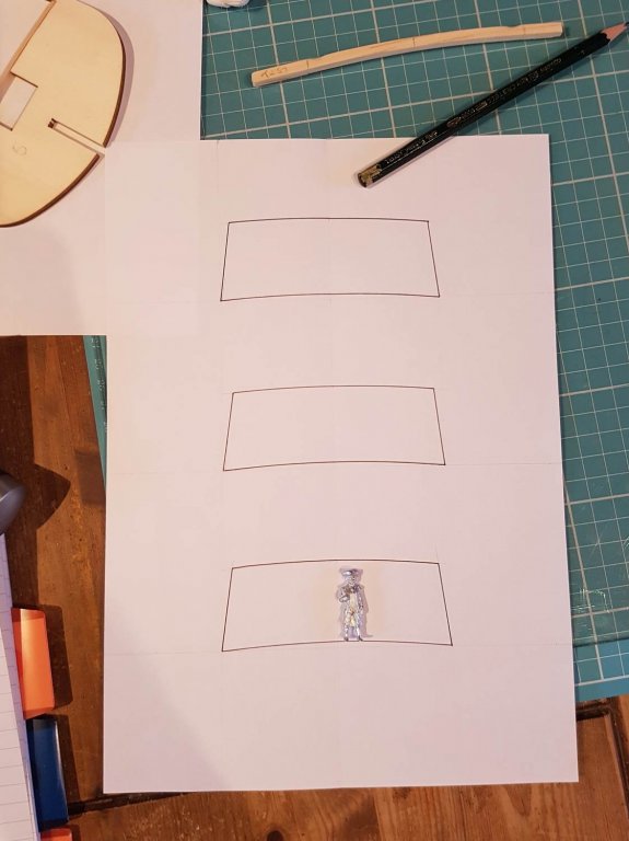
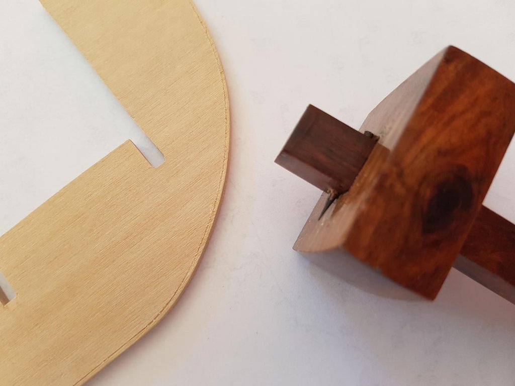
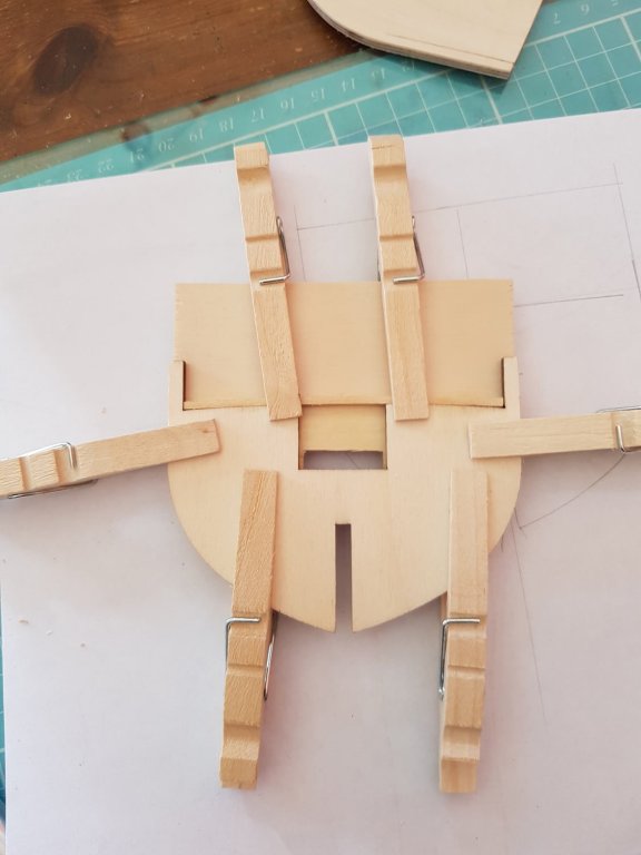
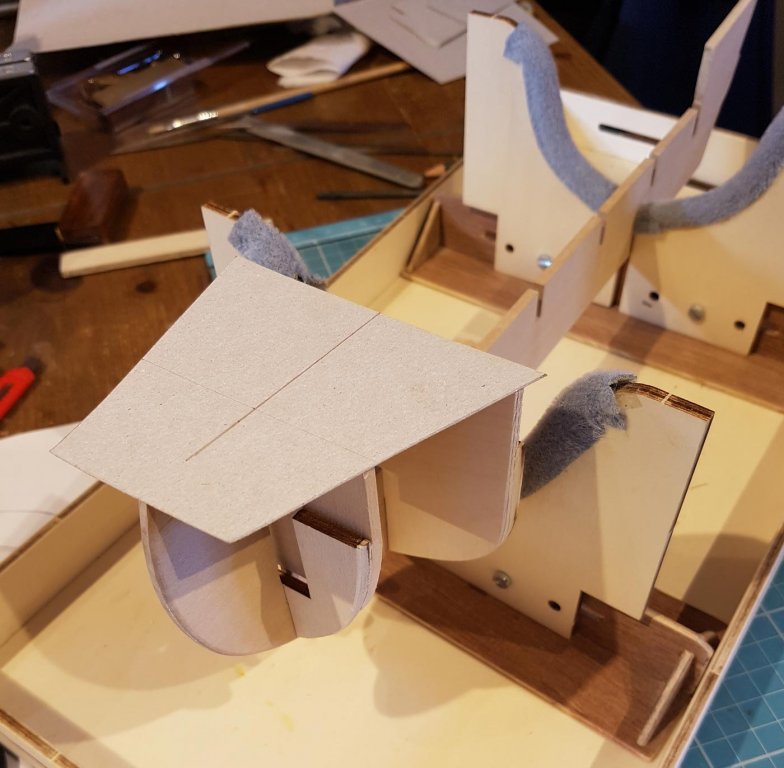
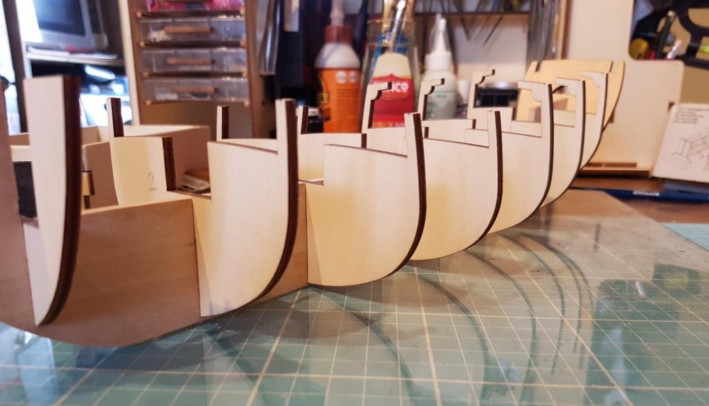
Hi everyone, just a little update from the past few days work. Not much tangible building work has been done but a fair amount of thinking , decision making and mind changing has gone on……. Firstly I prepared the false keel to accommodate the bowsprit, the main mast and the tiller; I cut the inside of the bow at an angle (taken from the “plans” I drew). The bowsprit will lie against this so the angle of cut will be the angle of the bowsprit - the angle is 55 degrees from the horizontal. Zu Mondfeld states that medieval bowsprits are between 50 and 60 degrees, so I went for the middle ground. This big an angle will also let me have a sail on the bowsprit that’s high enough so that the figurehead can see ahead of her. I also cut a notch for the mainmast foot to sit in. I spent some time working out how the mast foot will be secured in the sideways aspect, I have come up with a plan which will be shown later. The stern of the false keel was notched to allow the initial part of the tiller. This space will be boxed in and painted black so it will give the impression of a full length tiller. I also cut a hole in the stern bulkhead for the tiller to pass through. It looks a bit small but my initial rough testing shows that it is big enough. The shape needs a bit of refinement - I purchased a stencil that will help me get a good oval shape - so the hole will increase in size slightly. I test fitted a piece of card to give me an idea of the side of the stern cabin area. This showed me that I still needed to adjust the angle and width of the upper parts of the bulkheads so that the walls of the cabin area are straight front-to-rear. The kit has the upper stern deck starting from bulkhead 5 but as you can see I am only starting from bulkhead 6 - this will give me a greater maindeck area. On the maindeck I need to fit forward and rear cargo hatch’s, a capstan and a fife rail around the mainmast. I will also need to fit two ships boats aswell somewhere…oh, and some pumps. Whilst test fitting Captain Kennit came aboard and kindly reminded me that the stern bulkhead had to be cut to allow the ”windows across the stern, if you would be so kind”. I decided that I couldn’t put off fixing the bulkheads to the false keel any more so I tested and tested with bulkhead 4 before I was happy, and then used the lego pieces CA’d to both the bulkhead and keel. I felt quite proud at this point…. …..And then the swearing started. I had got the bulkhead square, but I hadn’t glued the bulkhead/keel join - and while the CA was doing a good a job at the top, there was no strength in the join at the bottom of the keel. So I glued a couple extra lego pieces towards the bottom and run some aliphatic glue along the joints. After the glue dried it was stuck fast! After I glued (properly this time) bulkhead 3 I started thinking about bulkheads 1 and 2. My original plan was to have no side-to-side camber on the fore and stern decks, but whilst some medieval era artwork doesn’t show any camber on these decks, all the pictures I could find of real ships all showed a camber in this area. Bulkheads 1 and 2 with the camber, again some refinement will be required. I had been considering how to build the stern cabin area. I think the easiest option would be to build it as a separate component off the model and attach later, but it just doesn’t “feel” right. Building a hatch or capstan off the ship feels ok but the cabin area should be part of the hull structure and built with the hull. Quirky I know but I’ll feel happier building a ship rather than a bunch of components. To start off with I made a jig to bend the deck supports for the stern deck and tested it with a piece of basswood; It worked, but didn’t look symmetrical. I am constantly amazed at how the human eye can see such tiny discrepancies, I never noticed while building plastic models. I can see when something isn’t square even down to an unmeasureable fraction of a degree. So to ensure the jig was symmetrical I drew round the curve onto a piece of paper, flipped it over and compared the curve. I then sanded where it was needed and tested again. After doing this a few times I tested the jig again. Back to the false keel; The foot of the mainmast will fit into the small rectangular hole. I stuck on a couple of flat pieces to give extra gluing area when the time comes to fit the mast. I drew up a template so I could decide on where the windows and doors would go on the bulkhead for the stern area. Captain Kennit advises that he is definitely not lying down on the job just “merely indicating where the door should go….” Not much building to show for a week or so, but I’m getting there……… I was hoping to get in the shipyard a lot this week but Daughter #1 and Granddaughter#1 turn up tomorrow for a few days………… Cheers, Paul


-
Thanks for your comments Katsumoto. I seem to spend most of my time thinking; every time I think of doing something I find that there are 3 things I need to do first! I have to keep reminding myself this is a marathon not a sprint...…. Mark, didn't see the film but I'll keep those words in mind, Thanks! Cheers, Paul
-
Thanks Mark, this build is turning out to be 90% thinking, 5% building and 33% swearing at the moment! I think the Gauge Marking Tool Thingy came with a set of carpenters squares. Its one of those tools that I have had for ages but never actually used! It probably wasn't designed for making rabbets....
-
Excellent work! The windows look particularly impressive, she is going to be a great looking ship. Well Done, Sir!
- 236 replies
-
- 1
-

-
- artesania latina
- kitbashing
- (and 2 more)
-
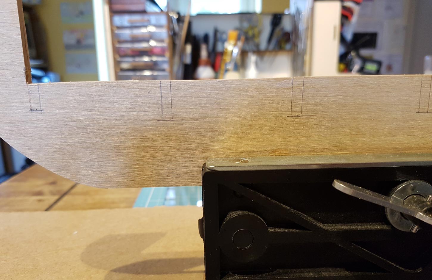
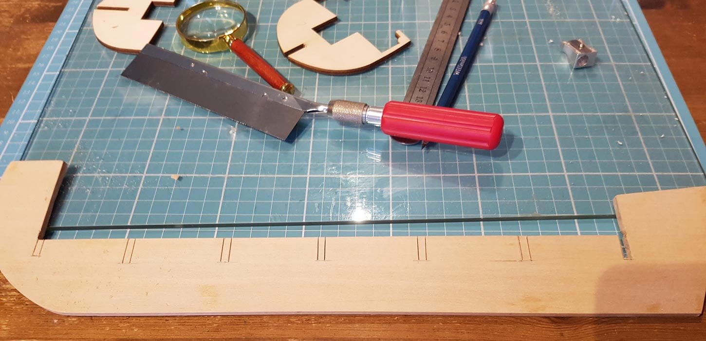
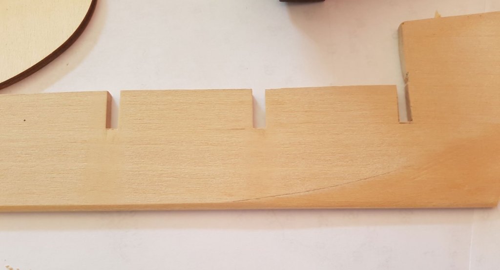
A productive couple of days in the shipyard, despite the enforced early finish yesterday. I knew that, because I had increased the distance between the bulkheads, and because there will only be one layer of planking, I was in danger of having flat spots between, and bumps over, the bulkheads in the planking. So I have decided to fill the gap between each bulkhead with balsa blocks - effectively giving a solid hull and a smooth base to plank on. I have decided to make a rabbet for the planking - I didn’t make one for the Virginia build so I wanted to make one for this build. My original plan was to make the rabbet in the false keel, glue on the keel, stem and stern post and then attach the bulkheads etc. However because I am going to infill between the bulkheads I am worried that I will damage the keel etc as I shape the hull. So attaching the keel, stem and stern post will wait until the hull is fully formed. This will mean that these won’t be as strong as they could have been so I will have to properly pre-bend the planking so as not to put too much stress on them. I knew I wouldn’t be able to mark the rabbet freehand so I used this gauge marking tool thingy; I marked both the sides and the edge then carefully planed off the excess and tidied up with 800 grit sandpaper. I also created the bearding line… ..and partially pre shaped the edge of bulkhead 1. I also lowered it slightly to fit the false keel. The transom bulkhead (no.8) was up next. I used my dremel to roughly shape the piece…. and then hand sanded until I was happy with the final shape. I added a 2ml batten to each bulkhead to raise the deck level. I have only added one batten at the moment, I think this will be enough, I can always add another one later. In the books the crew live in the forecastle so I wanted to raise the foredeck to give the crew at least some semblance of headroom. To achieve this I added an extra part to bulkhead 2 - this will provide the base for the foredeck and extend the side of the hull up to the foredeck. The deck-planks will butt up to the new piece and I can build the visible bulkhead with window and door in front of the new piece. I also extended bulkhead 1 - and test fitted a mock-up of the foredeck. It’s not the final shape - but just to give me an idea of how things look - Whilst checking the hull and bulkhead fitting I decided that the rabbet I had made earlier may not be enough. Rooting through my wood stock kept from the Virginia build I found a 2x2mm batten, soaked it for 10 mins and formed it around the keel and stem. It might be a bit thick but I can always sand it down but I won’t know until I have glued the bulkheads on. It’s not glued on yet, like everything else on this build I’m thinking and thinking about when the best time for this will be…. But……I’ve been putting off gluing the bulkheads onto the false keel for long enough……… I think that has to be my next step… wish me luck…….. Cheers, Paul.


-
Hi Mark, Thanks for your comments, though the helpers, and Capn Kennit in particular, weren't happy with me today as I ignored the saying of measure twice cut once"! After getting a 2x4 across the back of the head from the disappointed Pirate I put the shipyard away early today.... I noticed that fix you did on your log, unfortunately my false keel was also bowed top to bottom so the keel was completely unuseable. I hope you get your stern problem sorted soon, just from your pics it looks like part 17 is the incorrect shape? Good Luck! Hopefully I will get the shipyard out tomorrow and have an update tomorrow night. And thanks for all the likes everyone, I do appreciate them. Cheers, Paul
-
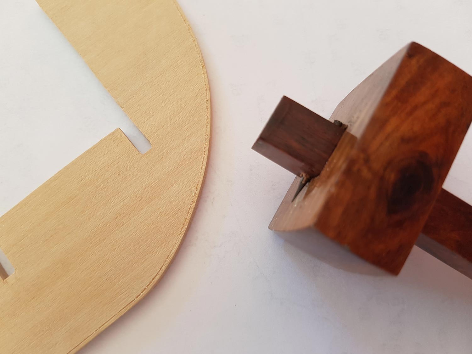
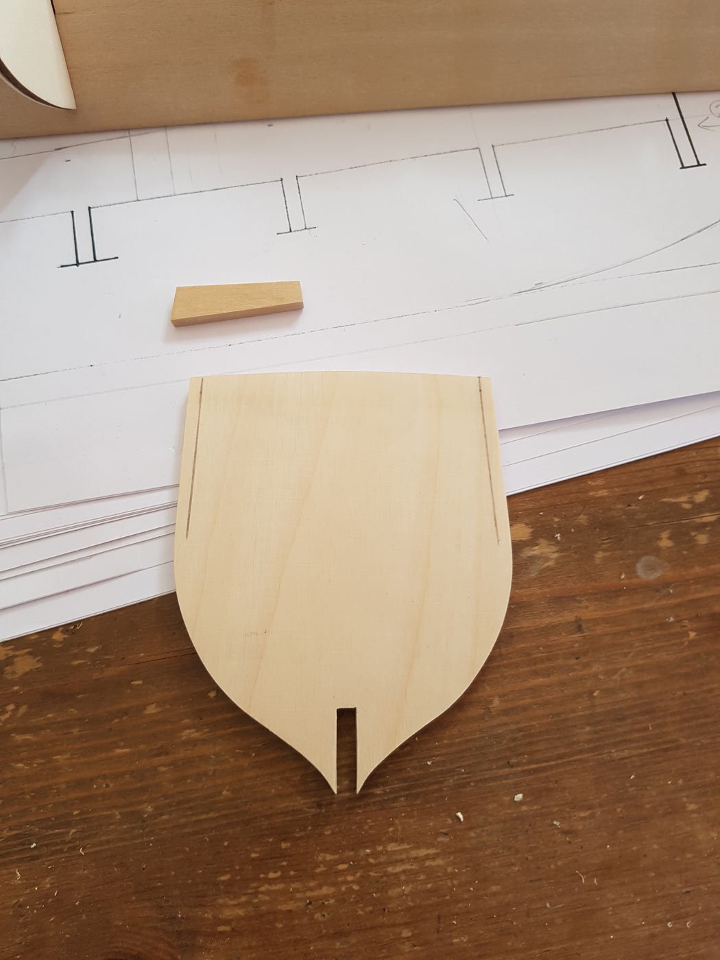
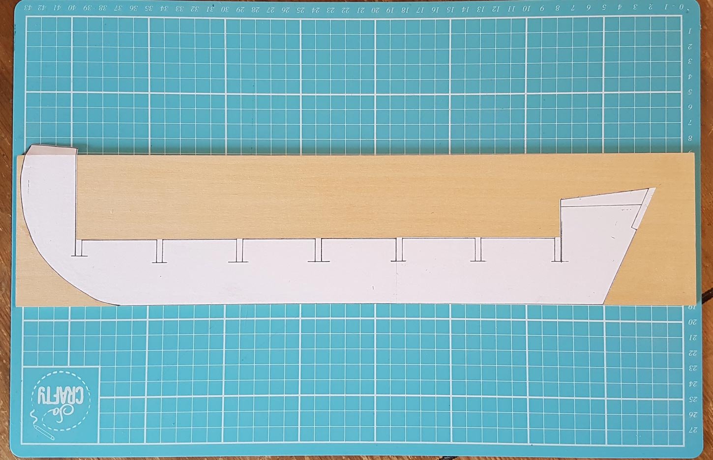
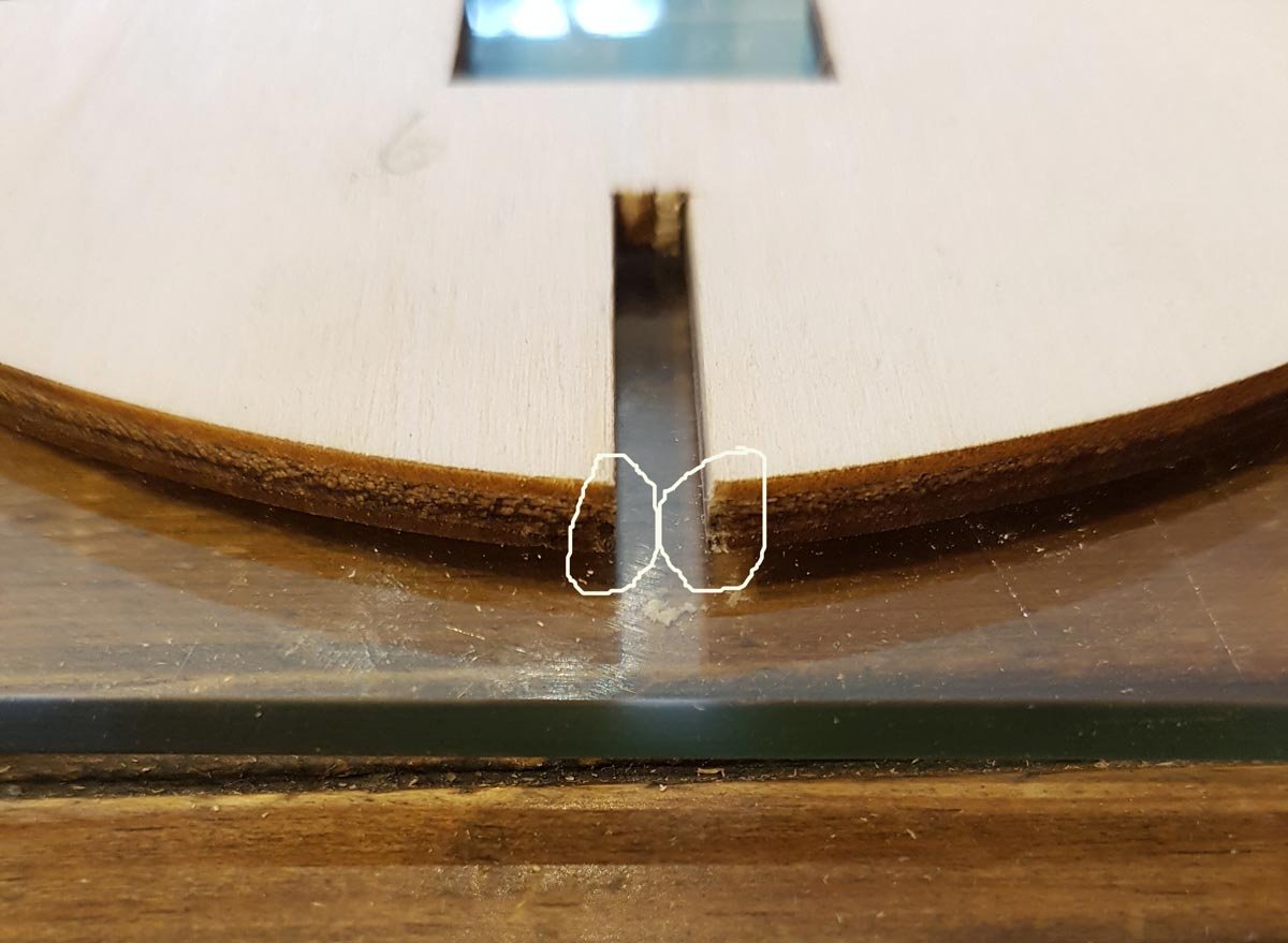
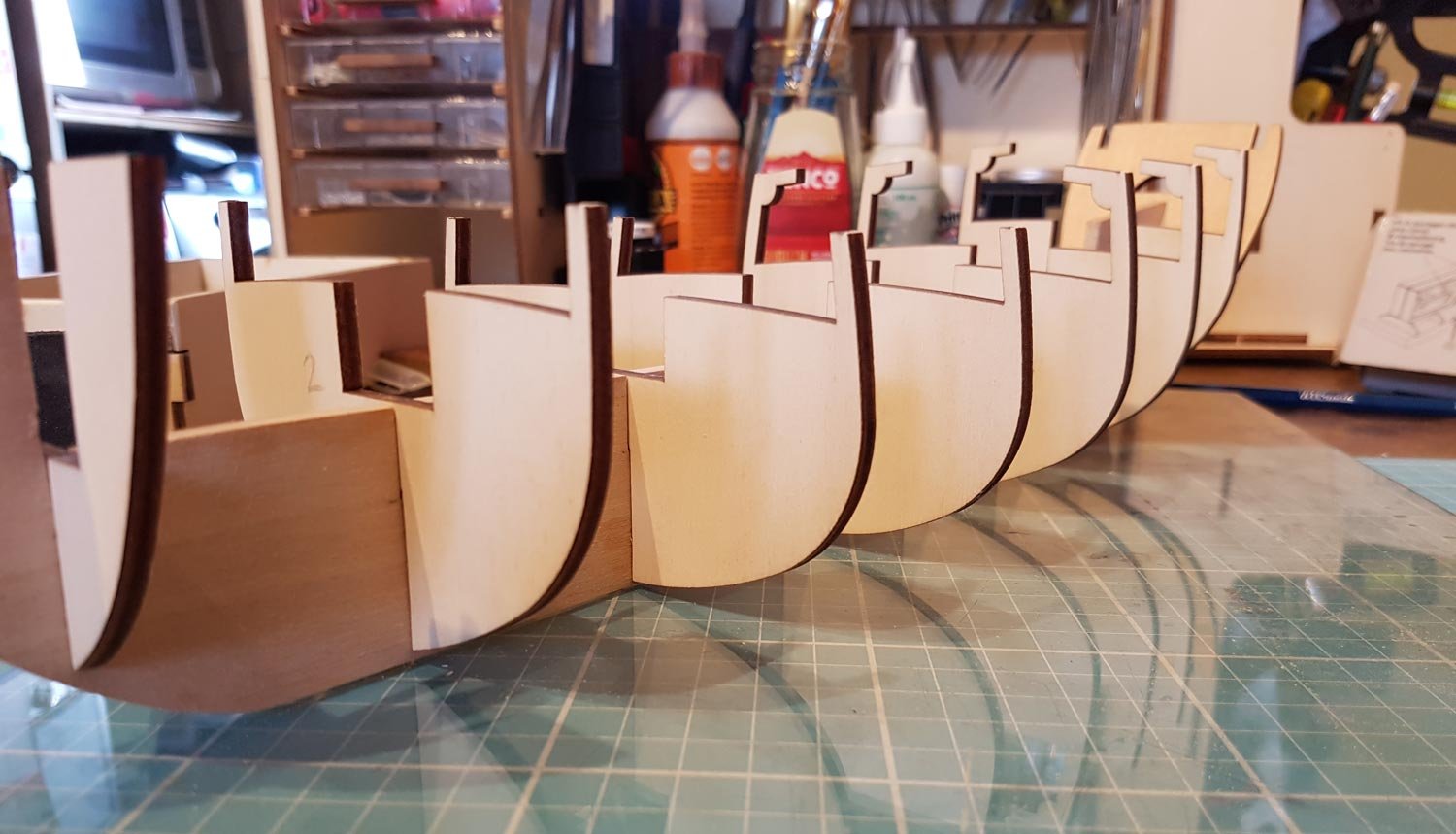
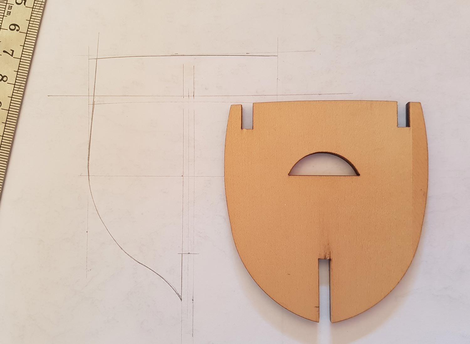
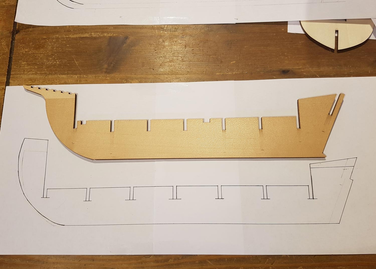
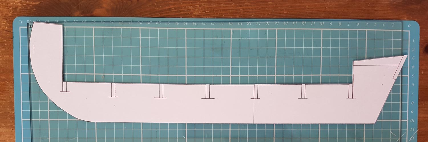
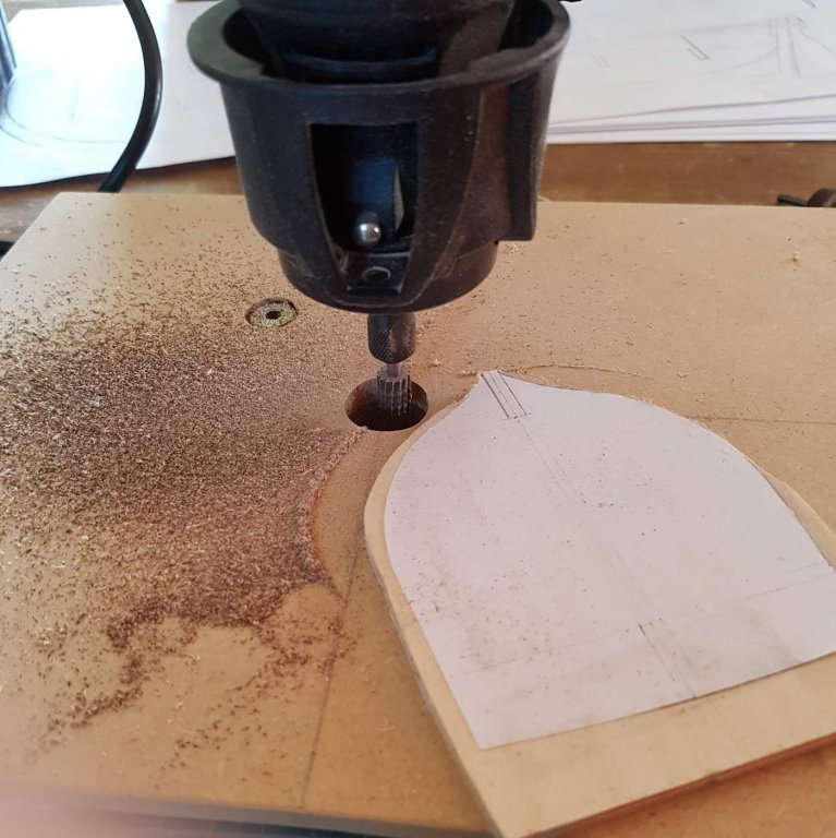
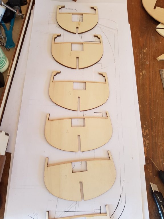
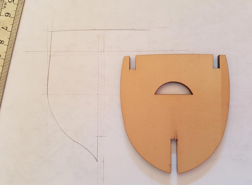
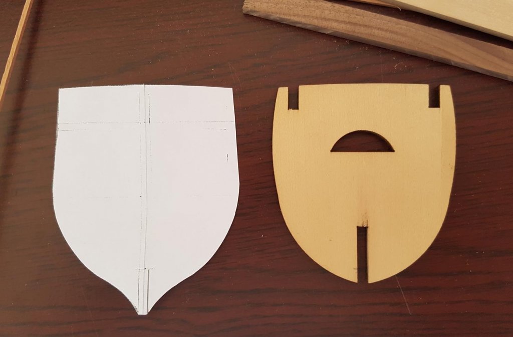
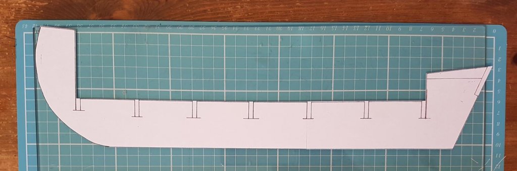
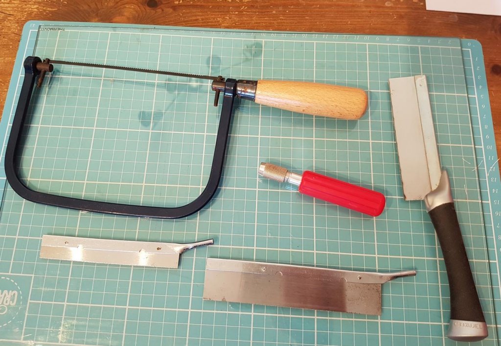
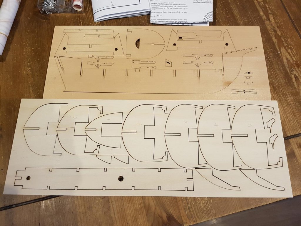
This weeks work began by gluing the plan for the false keel to a piece of 4mm lime. . I used “pritt stick” to glue the plan, not knowing whether this was a good idea or not. As it turns out it worked very well; after cutting, the plan and glue came off after wetting with a damp sponge. The little bit left over at the bow was stuck to an offcut. I cut along each line with a scalpel blade, removed the plan and went over each line with a sharp pencil. I used a fretsaw to roughly cut the outer shape and then used a mini plane to clean up the edges. The cutouts for the bulkheads were removed one by one. The first bulkhead fits!... …and so does the second. I am very proud at this point…. I continued to remove each cutout and noticed that every bulkhead didn’t sit perpendicular to the false keel. I was annoyed at myself for not cutting straight but no matter how carefully I filed the cutouts I could not get the bulkheads to sit right. I took me quite a while to work out that the error lay with the kit bulkheads and not my sawing. The cut out on each bulkhead (as circled below) was not cut at a 90 degree angle. Being laser cut I had assumed that they would be… Test fitting all the bulkheads after fixing the “square” problem… I intend to CA glue lego bricks at the bulkhead/false keel join to ensure they are at 90degrees. I spent an afternoon in the week sharpening the plane irons in my miniature hand planes, where I was reminded of the old adage of buy cheap buy twice - the cheap honing guide I had bought had a wonky wheel. I managed to find a sweet spot on the wheel so I had to sharpen the irons with very short movements. Lastly this week I turned to the transom bulkhead. I wasn’t happy with the shape of it, and it wasn’t symmetrical either. So I designed a new shape that I thought better suited a carrack/caravel. After some trial and error I came up with this shape; (the kit bulkhead on the right) After folding the paper in half along the centreline I cut it out. This is the shape at the moment. The sharp eyed may have noticed that the cutout to attach to the false keel is shorter on the new bulkhead than on the original; this is to "raise" the bottom of the hull - effectively allowing more water to flow over the shortened rudder. It is also taller, the top intending to be the upper deck support but depending on how I decide to form the cabin area I may only use the bottom half as the top half will dissect the captains cabin, or probably cut out the centre area of the top half leaving a vertical frame on each side, but that is a decision for later. However my first decision is hull v rabbit v keel , but that’s after a good nights kip... Cheers Paul


-
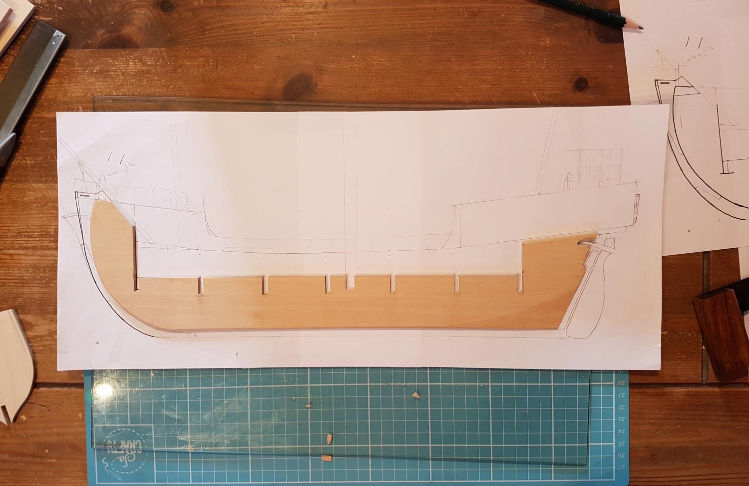
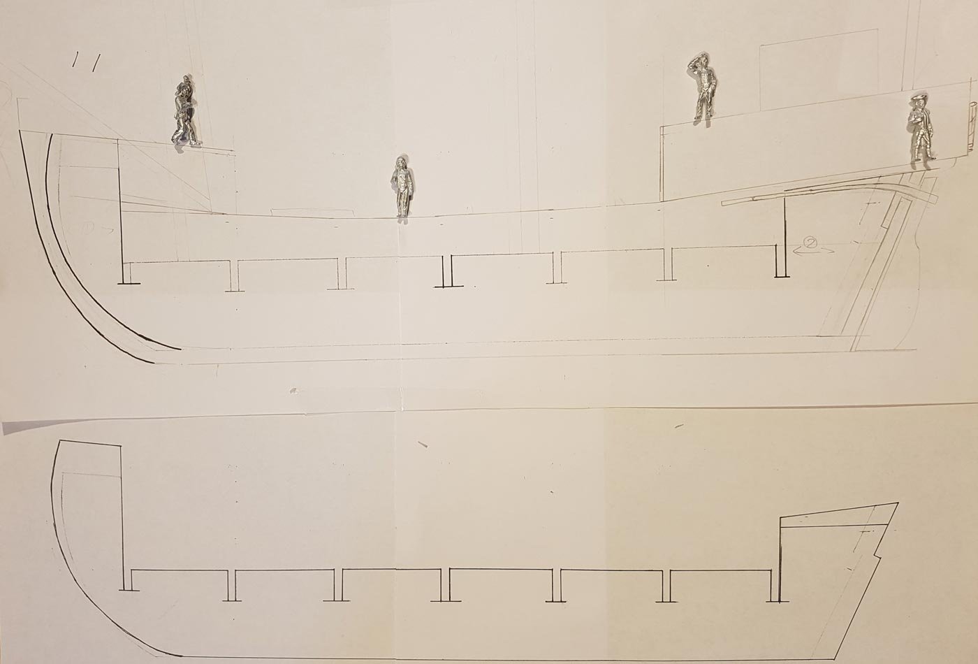
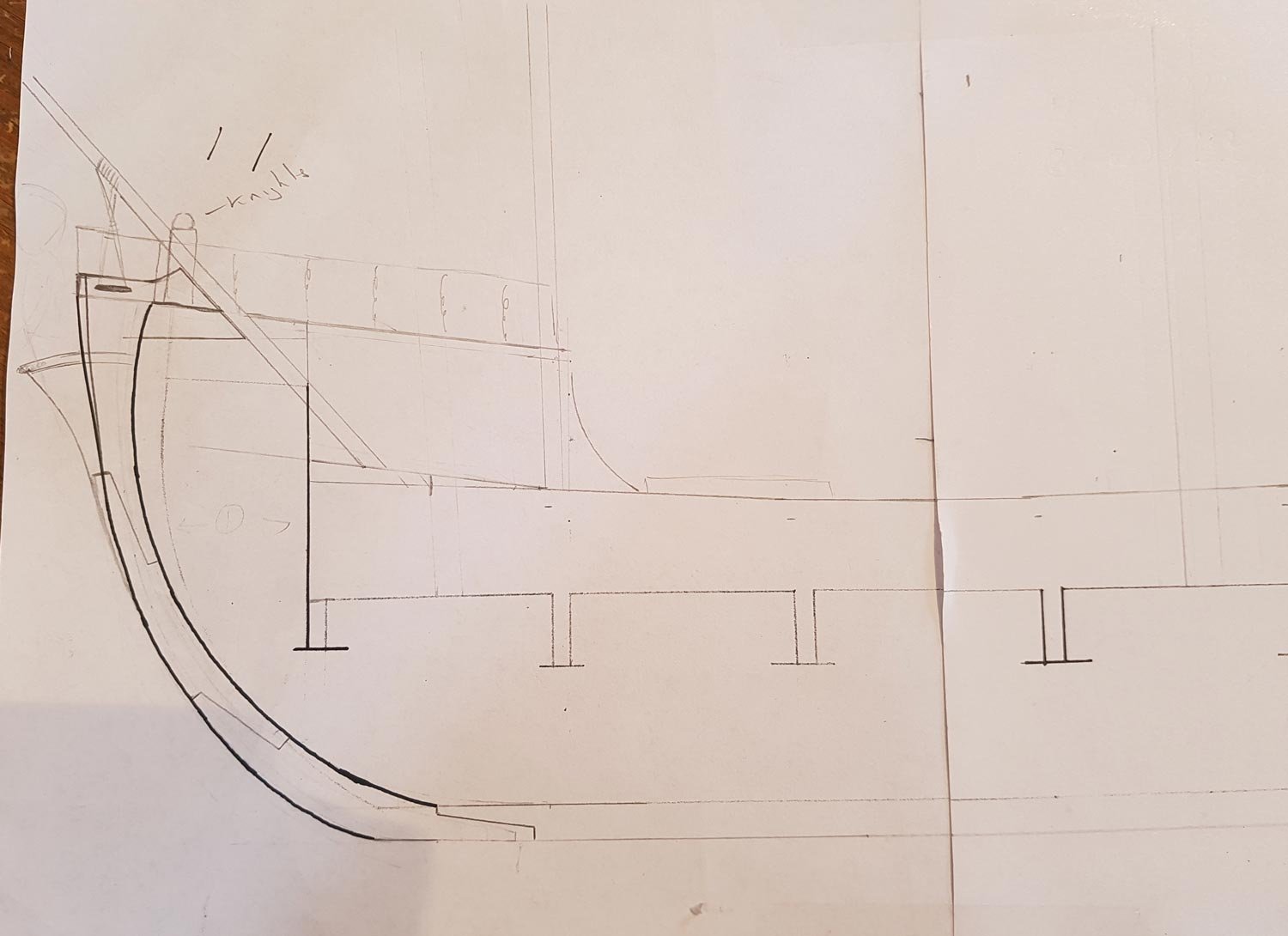
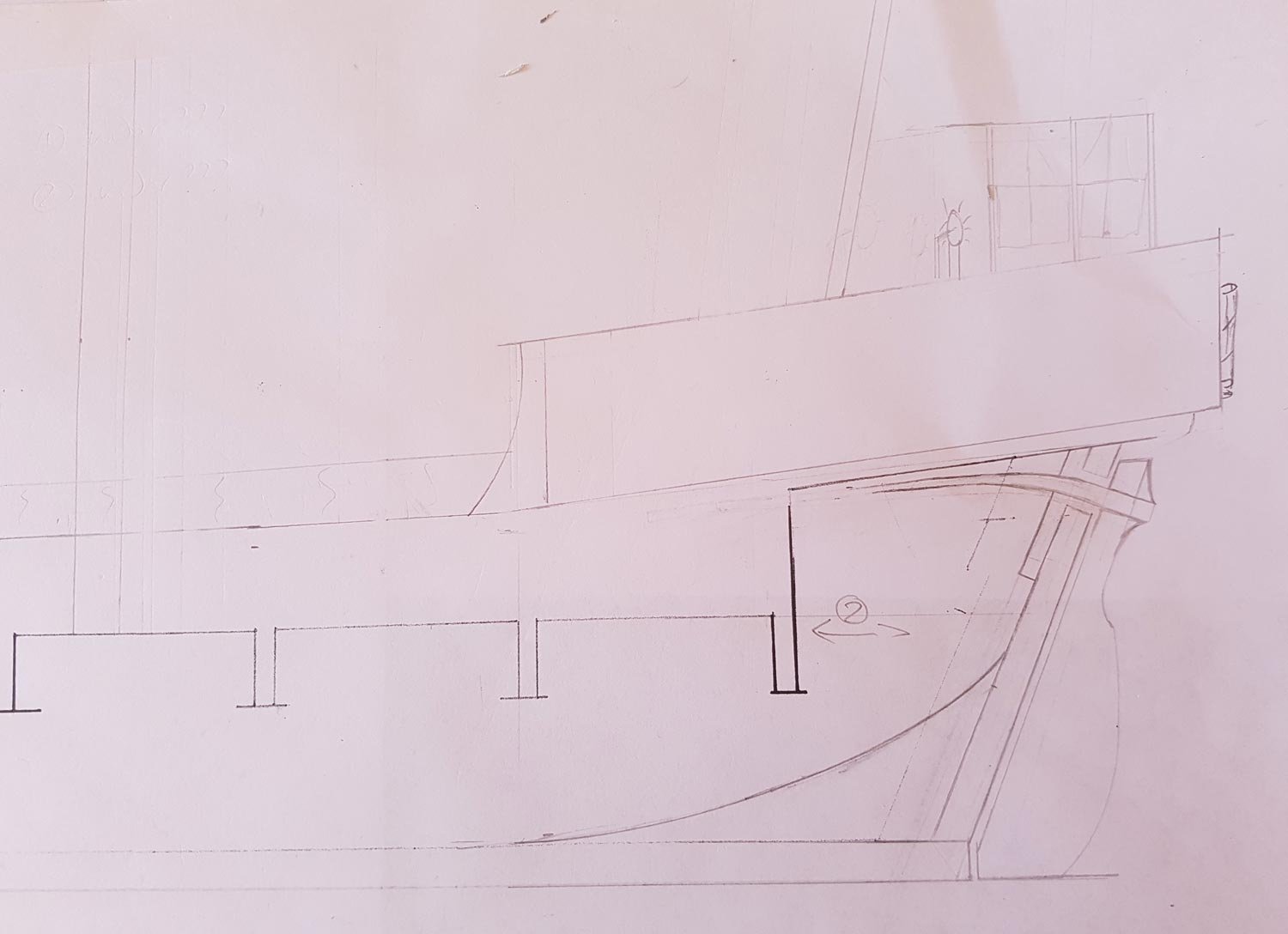
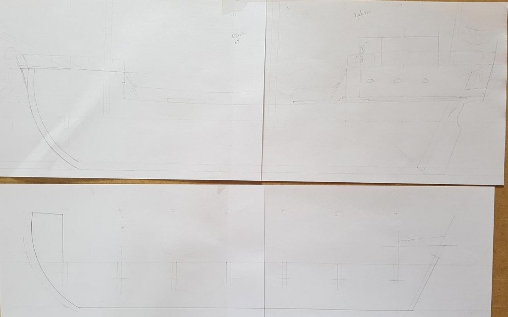
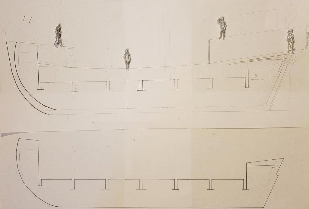
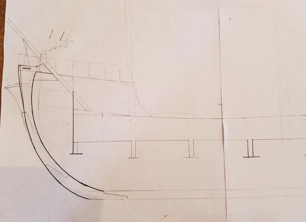
When I started looking over the Pinta kit and plans I realised that there were several areas that I needed to think about before I started cutting, glueing and sanding: Scale; The kit is 1/50, which meant that the Pinta was smaller than I had imagined the Vivacia to be. I eventually decided to lengthen the keel and change the scale to 1/64. I chose 1/64 as it seems to be a standard in model shipbuilding. it is a new scale for me as I am used to 1/32nd and 1/48 so its lucky that some 28mm helpers turned up… The Pirate, Captain Kennit, who has for so long been desperate to possess a Liveship, has brought some of his adoring and loyal crew to ensure the construction proceeds in a most satisfactory manner. The lengthened hull means the Vivacia will equate to an approximate length of 93 ft with a width of about 26 ft. The Bow; I knew that I would have to change the bow to accommodate the figurehead of Vivacia herself. I will change the triangle shaped foredeck into a trapezium - the books mention several characters leaning on the forerail talking to Vivacia, depending on my skills and how it looks I may be able to make the foremost portion of the deck and the forerail curved rather than straight. The Stern This is the area that has taken the most time to work out because on Vivacia there is a ships wheel for steering, and the area under the stern deck comprises of the captains stateroom plus cabins for the first mate, second mate and carpenter, the galley and chart room. Initially I thought that all I would have to do would be to close of the area under the stern deck and add windows etc. However in the kit this area houses the tiller. To cut a very long story, and many many drawings, short, I decided to raise the deck by about 4mm and shorten the Rudder. These are my initial drawings/plans with Captain Kennit ckecking the headroom in his stateroom; After much headscratching here are the “final” draughts for the Bow and stern areas, ( I think the foremast will end up being moved forward to allow a pinrail on the aft edge of the foredeck) The false keel is the one big letdown of this kit - it was badly warped in both axis. so my original plan of cutting the keel in half and adding a section in the centre was not going to work. So I drew a longer keel and increased the gap between each bulkhead by between 5 and 8mm. Time will tell if this changes the shape of the hull too much. Original false keel and new plan; Are you getting the impression that I’m making this up as I go along? Because that’s exactly what I’m doing… So to paraphrase an engineer from Apollo 13; I have to make this from this using nothing but this Thanks for looking Cheers, Paul


-
Thanks for your comments on the Virginia build, Fright, I'm hoping to reduce the number of obvious mistakes on this build...….. Sorry Mark, I left the popcorn at your build...….. I'll fetch some more!
-
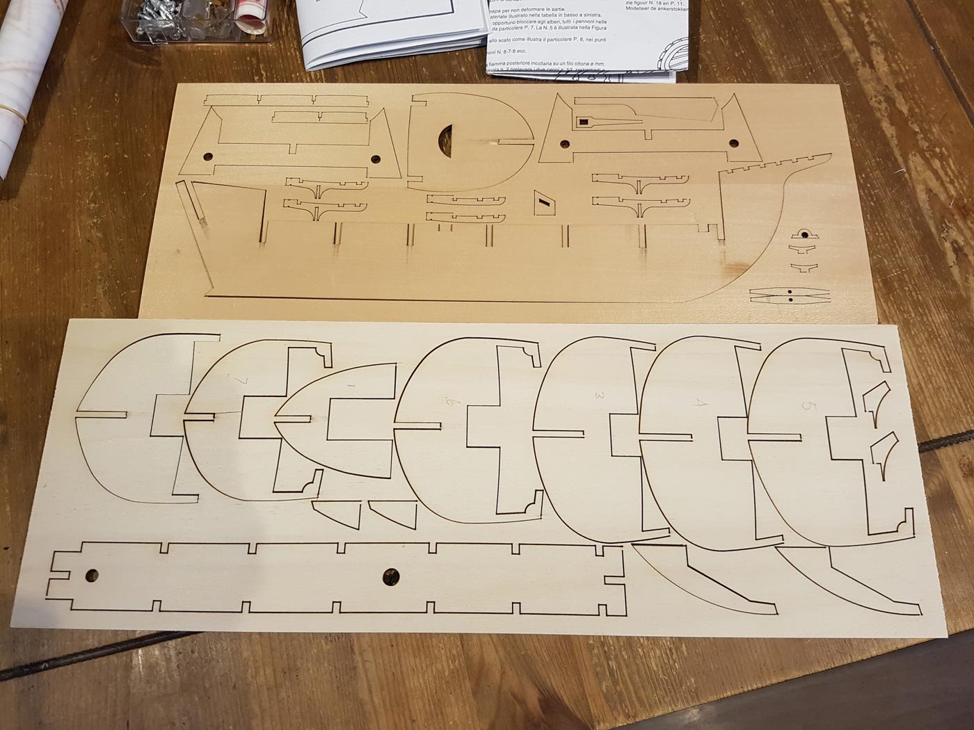
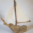
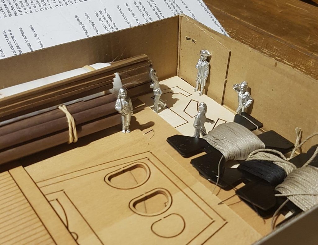
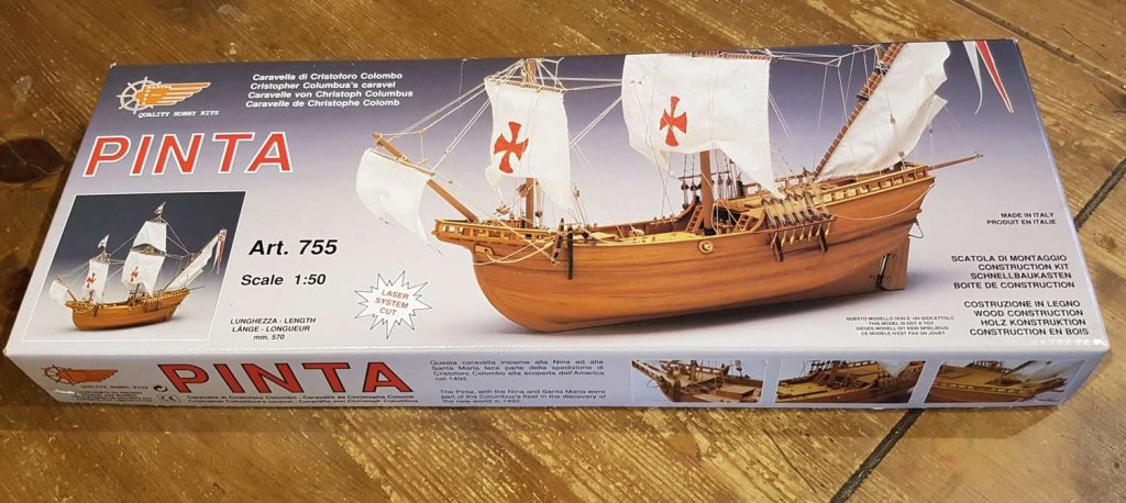
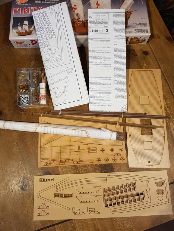
Hi and welcome to my build log of the Liveship Vivacia. This model is not based on a real ship but comes from the fantasy novels by Robin Hobb. My ambition is to build the Bounty, but I feel that I need more experience before I start such a project, especially in the areas of square sail rigging, hull planking and general component building (- basically everything, haha). So I have decided to build the ship that first got me interested in sailing ships when I read the books nearly 20 years ago. The books are fantasy novels based on a pre-gunpowder medieval style era, the ships mentioned are Caravels, Carracks, Cogs, Galleys and unspecified fishing and row boats. I have long wondered if it is possible to make an acceptable and “realistic” model simply from a novel. Repeated reading of the 3 novels in which this ship appears has convinced me that there is enough information to build a model that will fit in with the detailed description in the books. The Liveships trade along the coast and up and down certain rivers -think the eastern coastline of the North and South Americas - and while well-built and very expensive, are not ostentatious. The Liveship Vivacia is a merchant carrack/caravel style ship with at least two masts, raised fore and aft decks and transom stern. Due to a certain set of circumstances, these ships (made from a silvery grey wood), and the figureheads, eventually become sentient, hence Liveship. I know what you are thinking……. I won’t mention the magic and the dragons……… So I searched for a donor kit, eventually settling on the Pinta kit from Mantua. This kit has the required raised fore and aft decks, is multi masted, and a flat transom. It has square sails on the mainmast and foremast, with a lateen sail on the mizzen mast. Whilst the lateen sail won’t help with learning for the Bounty and is not specifically mentioned in the books, I’ve decided to keep it. To start off here are the pics of the kit contents; The kit itself is of a pretty good standard: single-layer hull planking in walnut, pre-printed sails, brass turned cannons and swivel guns, pre-formed pintles/gudgeons and other fittings already blackened, pre-cut decking, usual kit style blocks and triangular deadeyes and the usual laser cut plywood. This kit will need to be extensively kitbashed to achieve the result I am after and I expect this will be a project that will last me the next few years. I hope you will find this interesting and for those that wish to follow please pull up a chair, the beers are in the fridge! Cheers, Paul
-
Nice neat work. I am pulling up a chair to follow your build.
- 236 replies
-
- 1
-
-
- artesania latina
- kitbashing
- (and 2 more)
-
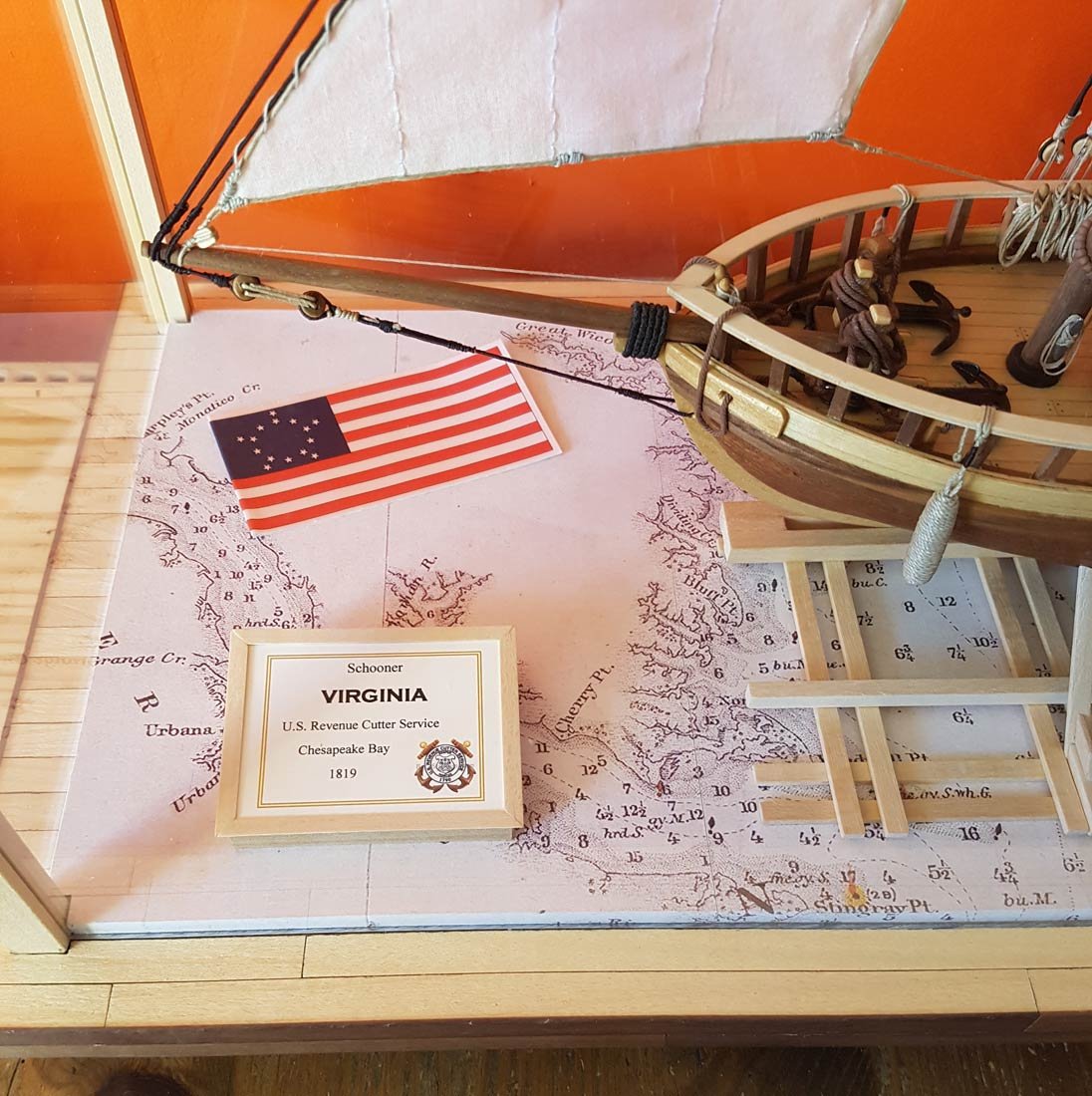
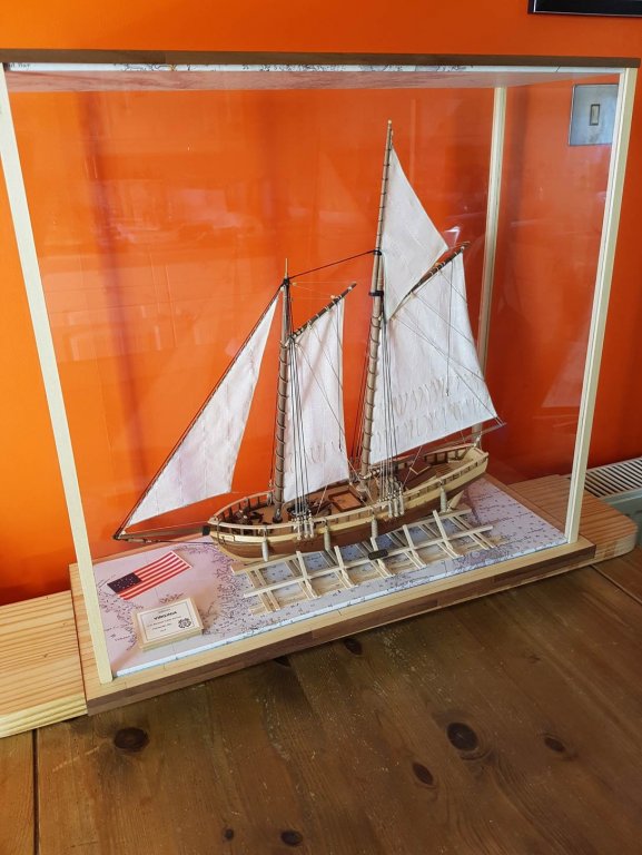
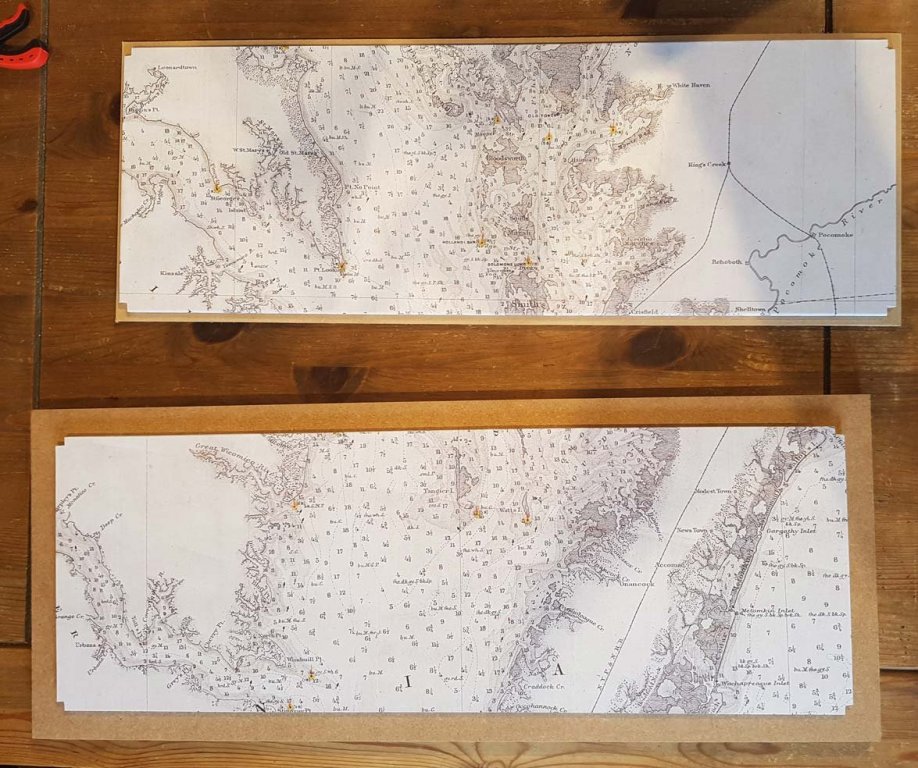
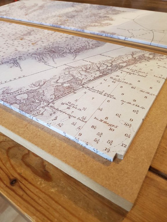
Hi Mark, good to hear from you. Thanks for your comments Yup I made the case, its not as "posh" as a solid wood one but its something different, which is what I was after. The covering is a printout of an 1892 map of the Delaware and Chesapeake Bays from the US Coastal and Geodetic Survey that I found online. I'm just in the "plan adjustment" stage of my next build. I hope to put saw to wood this week and start my log very soon.
-
Thank you for your kind comments, Ian. And thanks for everyones likes, they are much appreciated. I fulfilled my brief to finish up with something that - mistakes notwithstanding - I can be proud of. Gone, for me, are the days of plastic kits, I have fallen in love with sails and wood! I am already well into the planning stage for my next ship, the kit has been purchased, I'm just in the process of "adjusting" the plans. I hope to start my next log in a week or two..... Thanks again everyone Cheers, Paul
- 50 replies
-
- 1
-
-
- virginia
- artesania latina
- (and 2 more)
-
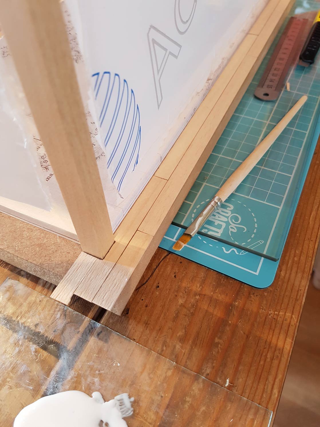
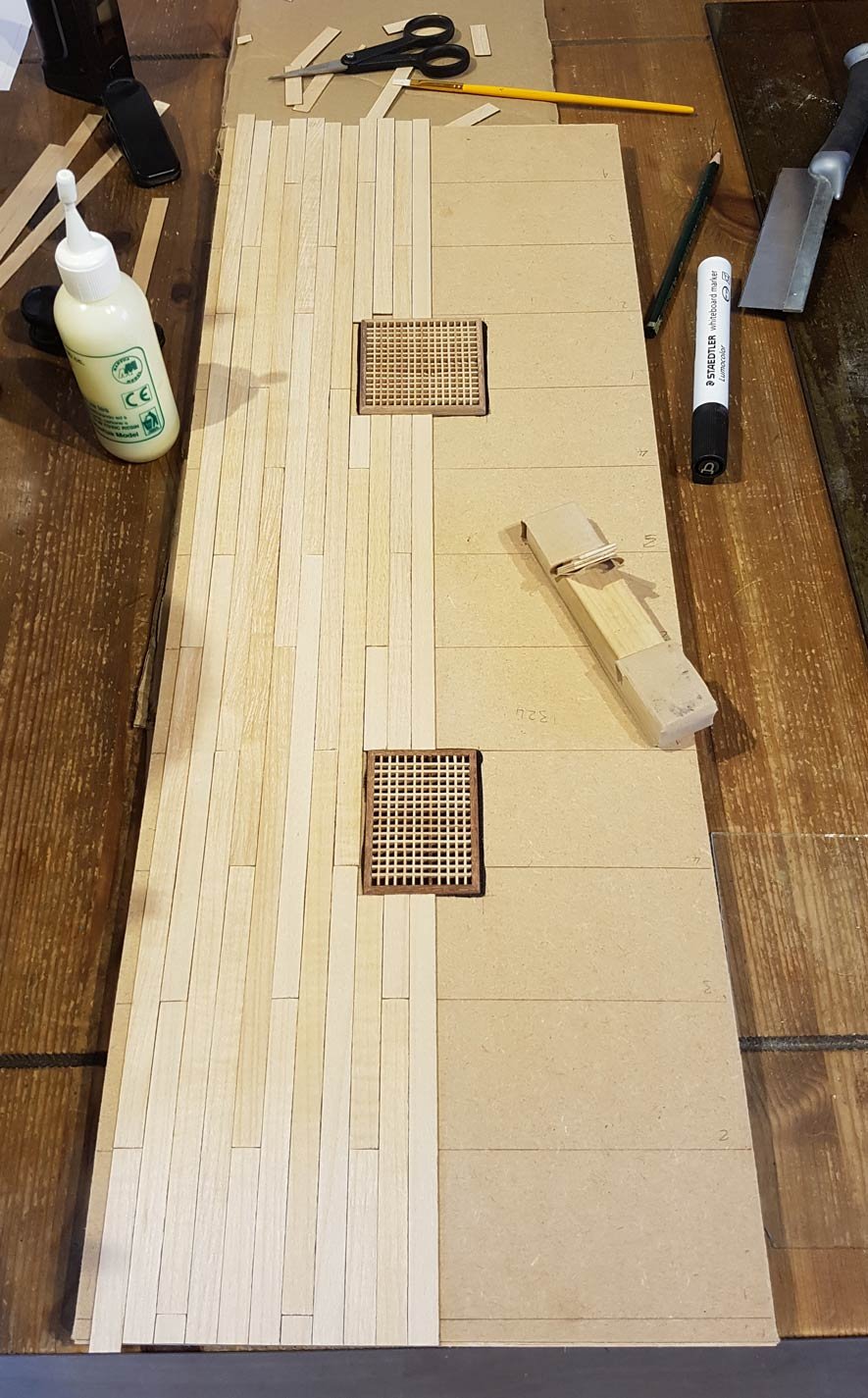
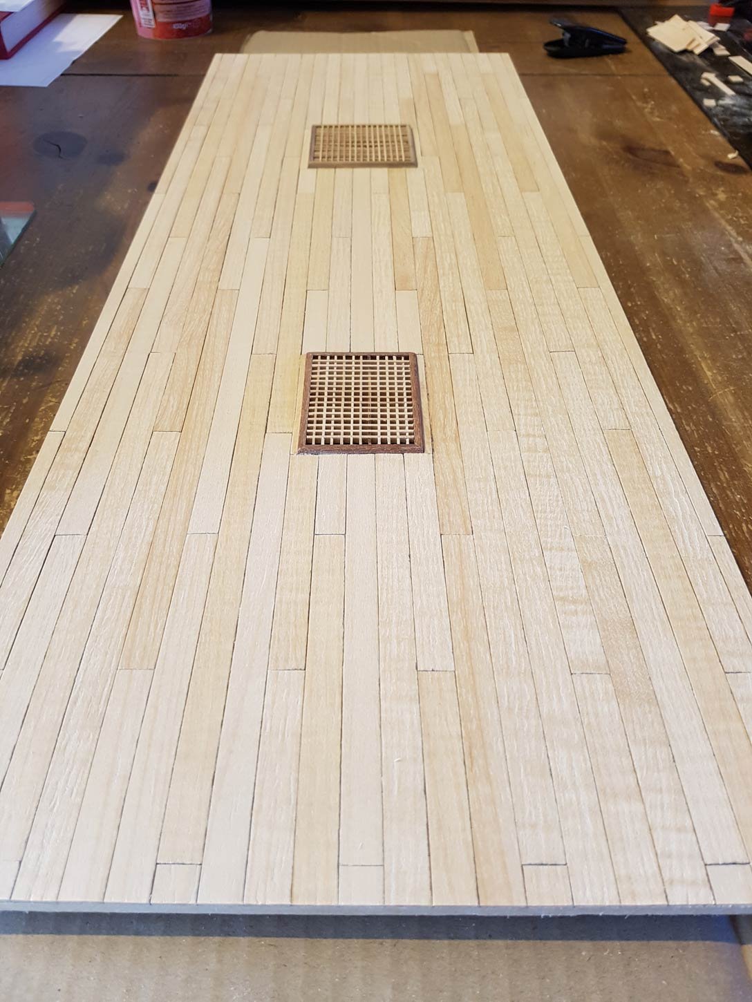
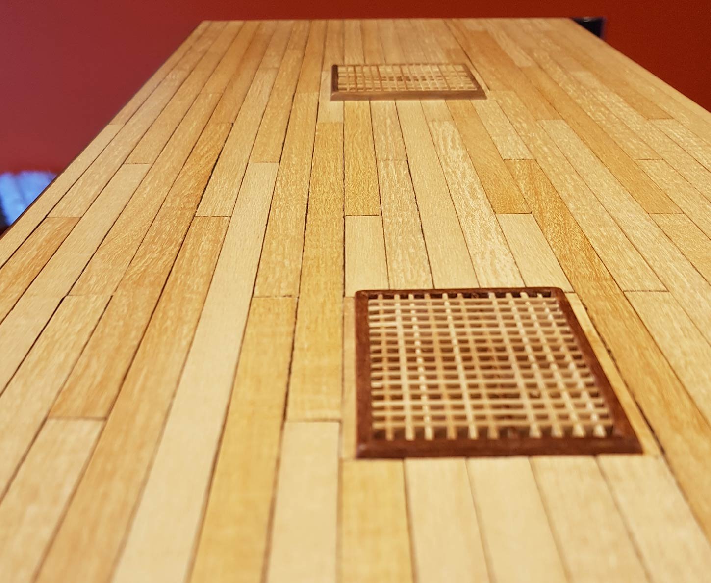
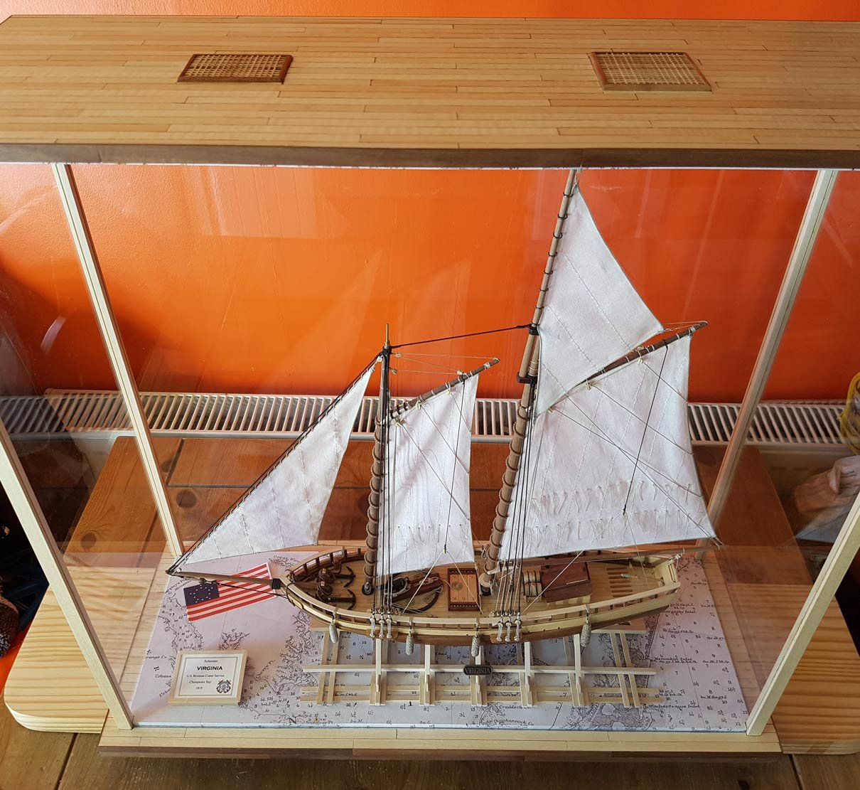
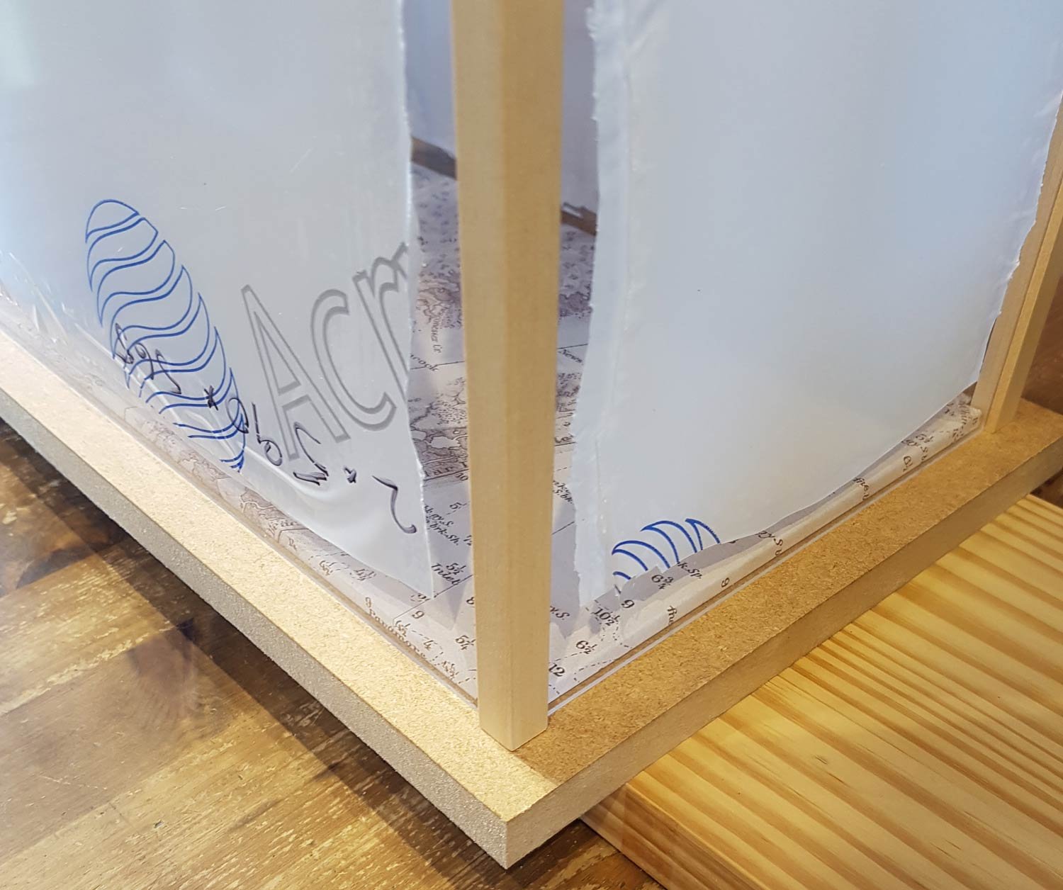
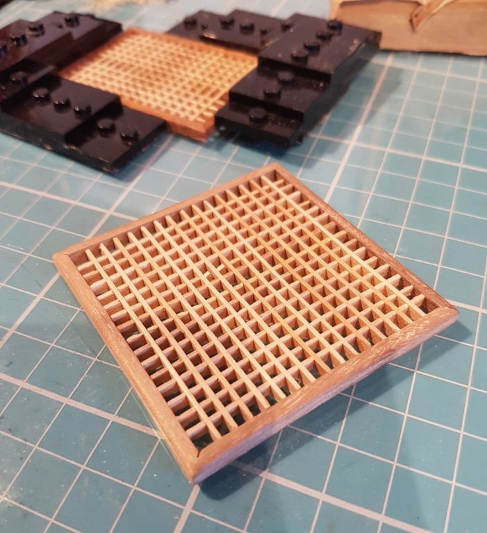
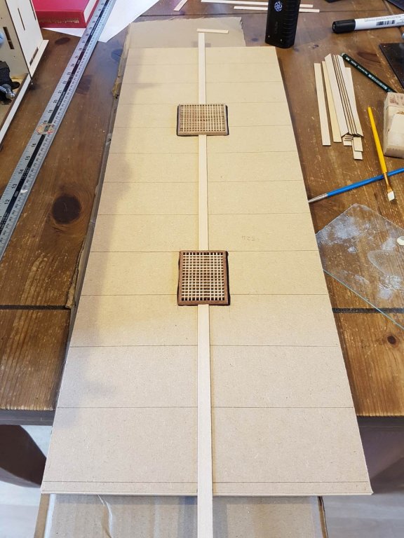
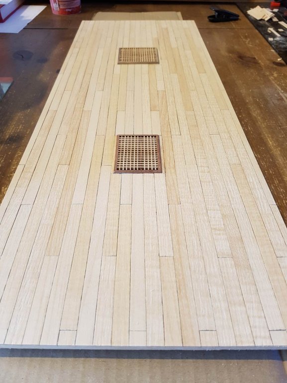
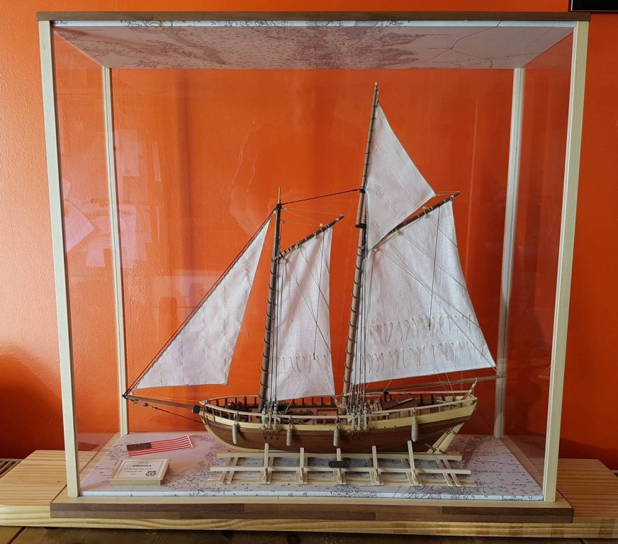
Originally my plan was to use some walnut sheets as a veneer over the MDF, but veneer always looks like veneer and I wanted something a little different. So I decided to take the veneer idea one step further and plank the case as if it were a deck and hull. I chose Maple for the horizontal/deck surfaces and Walnut for the vertical/hull surfaces. I started with the base, I thought that the top of the case would need a bit more than just decking so I purchased a couple of AL grating kits. These were made up and edged with some spare stock. I painted the top black where the gratings would sit and marked the centreline and the perpendicular lines for the butt shift guides. Here are the gratings and the centre plank glued on. Throughout this build I used Aliphatic carpenters glue which meant that very little clamping was needed. One half planked in a 4 shift pattern. The top completely planked and scraped and sanding underway. I used a standard double edged razor blade for the scraping, which proved that I need to invest in a good cabinet scraper. I also debated whether to indicate treenails. In the end I was worried that it would look too busy and that along with my fear that I couldn’t get them neat enough convinced me that for now I wont show them. The top was finished with Danish oil and a good buffing with a protective wood balsam/wax. I made a little box to display a name/detail piece and placed that and the kit flag on the base The completed display; Her home for the moment; Well, I've finished at last. Thanks for reading this log, I hope it has been of interest and helpful to anyone thinking of building this kit, even if only to show which mistakes to avoid! Now to start my next build…… Cheers, and Happy Sanding!


- 50 replies
-
- 18
-
-

-
- virginia
- artesania latina
- (and 2 more)
-
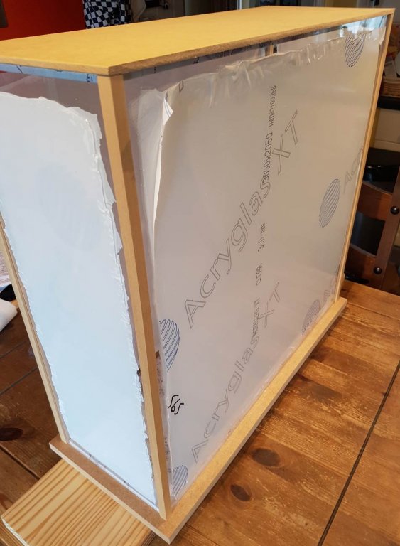
Hi all, I thought I’d add to my log as I’m building a display case for the Virginia. I have been thinking about the case for most of the build. Bearing in mind that the only power tools available to me is a dremel and a drill I knew I would have to make something simple. In the end I decided to use MDF for the base and top, and clear acrylic for the front, back and sides in 3mm. I ordered the acrylic online and ordered some 2 slot display case sections from CMB. The base comprises 18mm MDF with an inner base of 6mm MDF. The top is made from an inner and outer both from 6mm MDF. I downloaded an old map of the Chesapeake and Delaware Bays, printed it out and covered both the inners sections. The inners where the glued to the outers. I had to cut a little section out of each corner on the inners to fit the CMB sections. The boat fits on the base! The acrylic sheets were glued to the 2 slot sections using contact adhesive. Here they are test fitted to the top and base. Now I know that you are thinking that MDF doesn’t really do over 3 years work on the Virginia justice, and you would be right. So I have a plan….


- 50 replies
-
- 1
-
-
- virginia
- artesania latina
- (and 2 more)
-
Thank you Tjalle, after seeing your work, your words are high praise indeed. Good luck with your builds!
- 50 replies
-
- 1
-
-
- virginia
- artesania latina
- (and 2 more)
-
Thanks for the kind words Stevinne, I am pleased with how it turned out for my first attempt. I now have to start building the display case.........
-
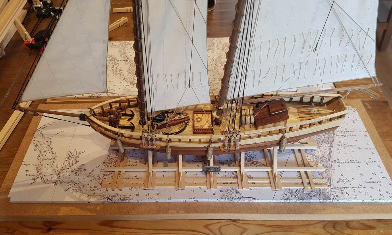
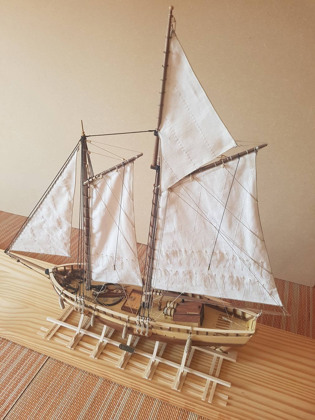
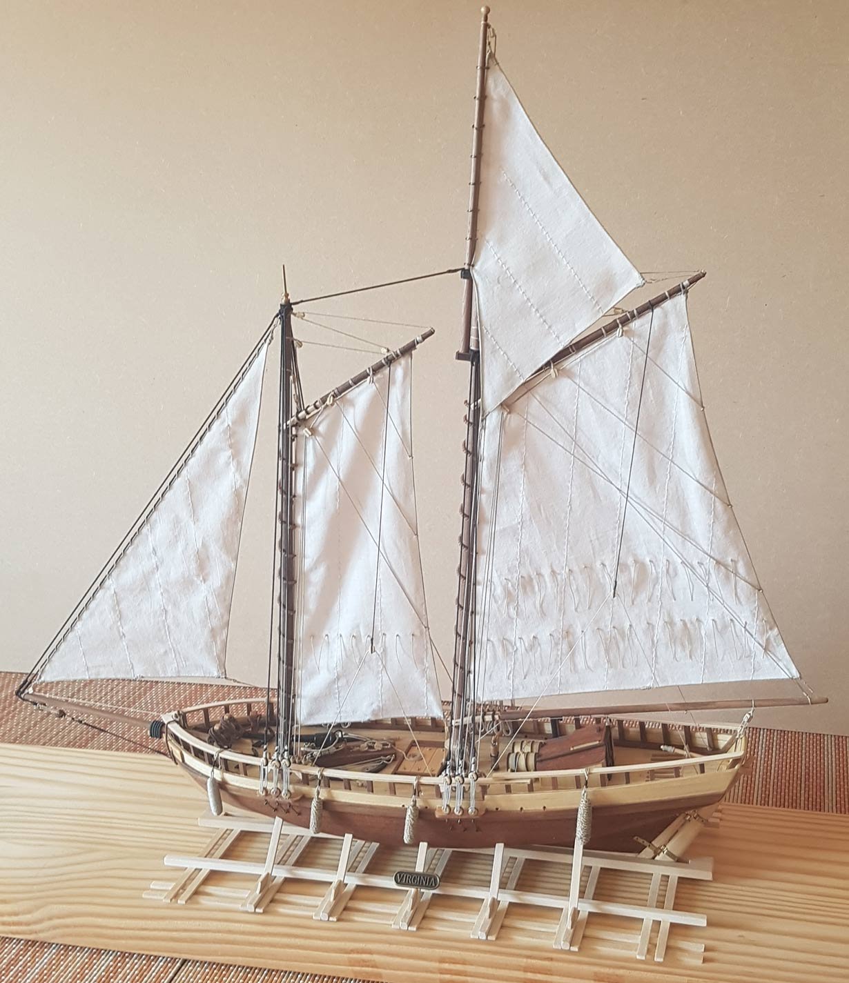
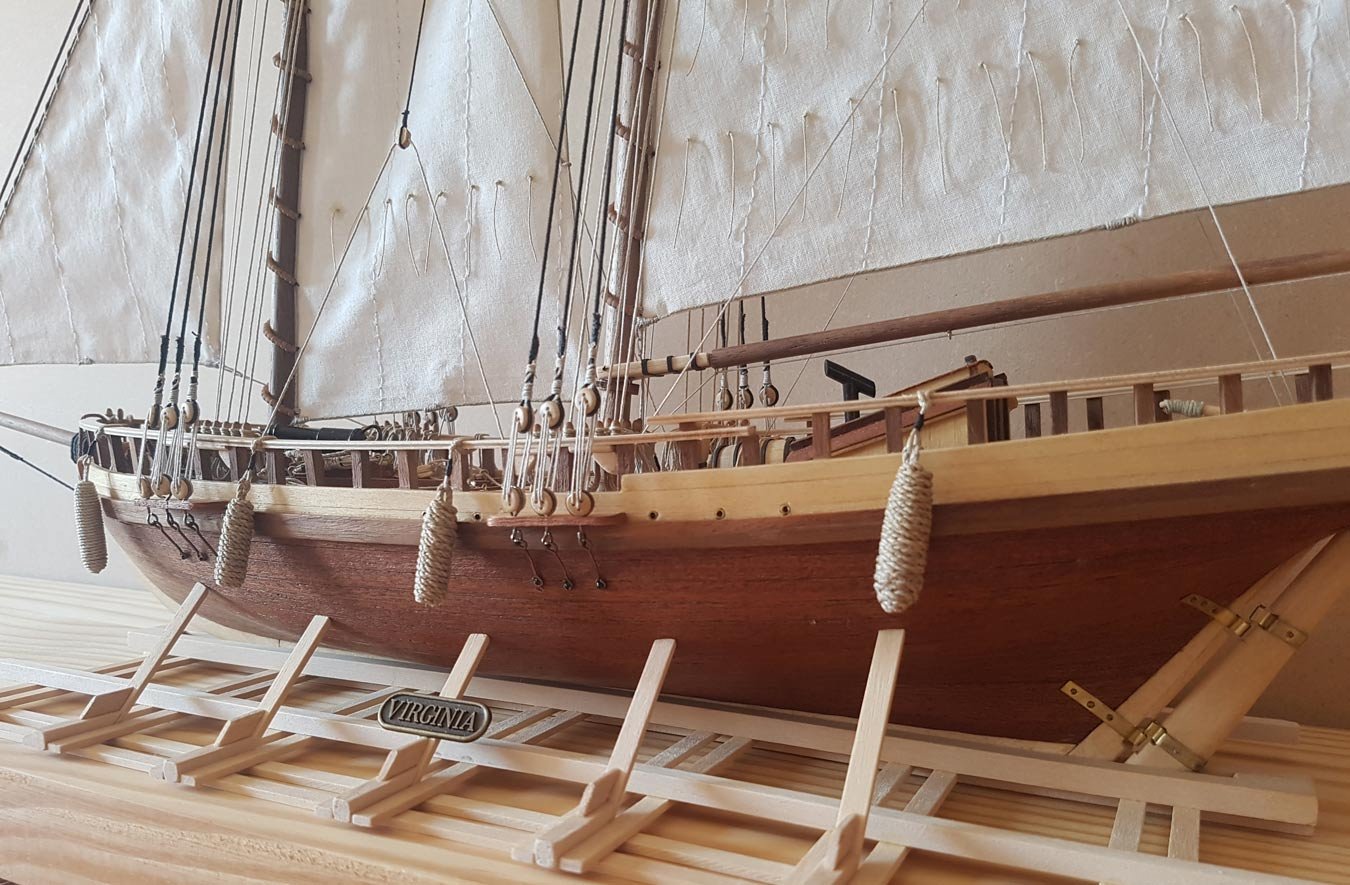
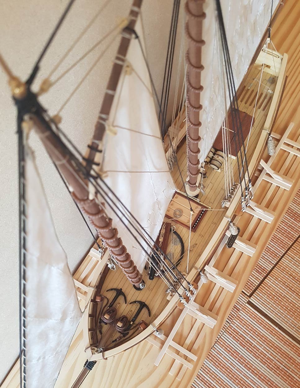
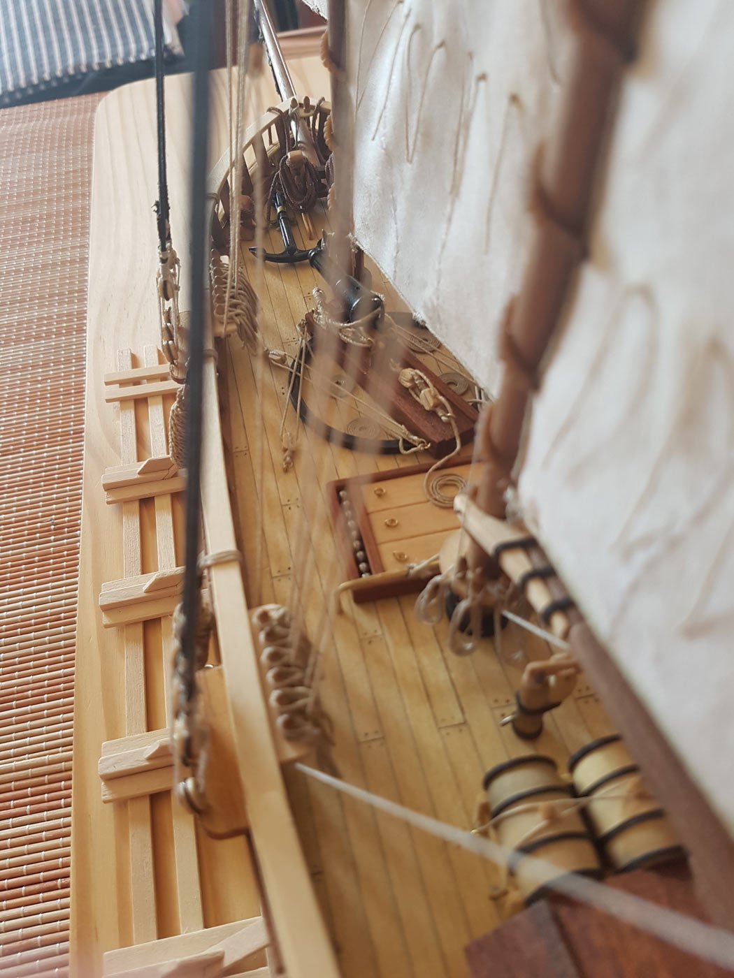
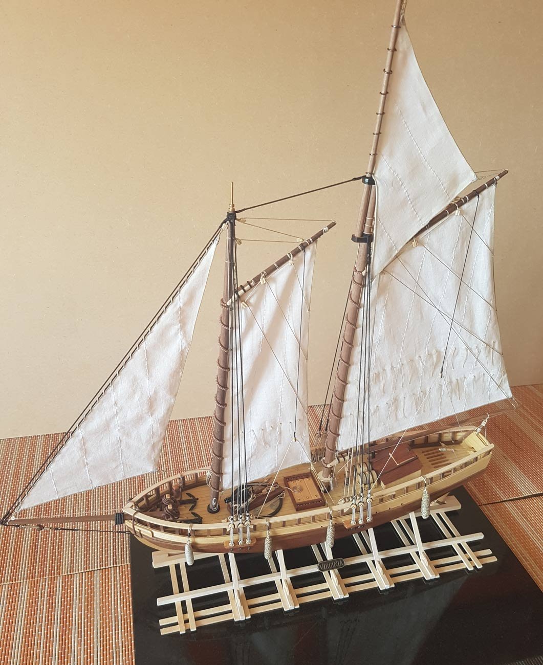
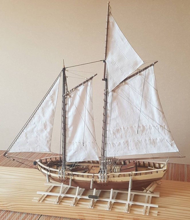
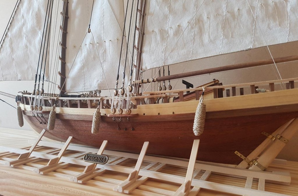
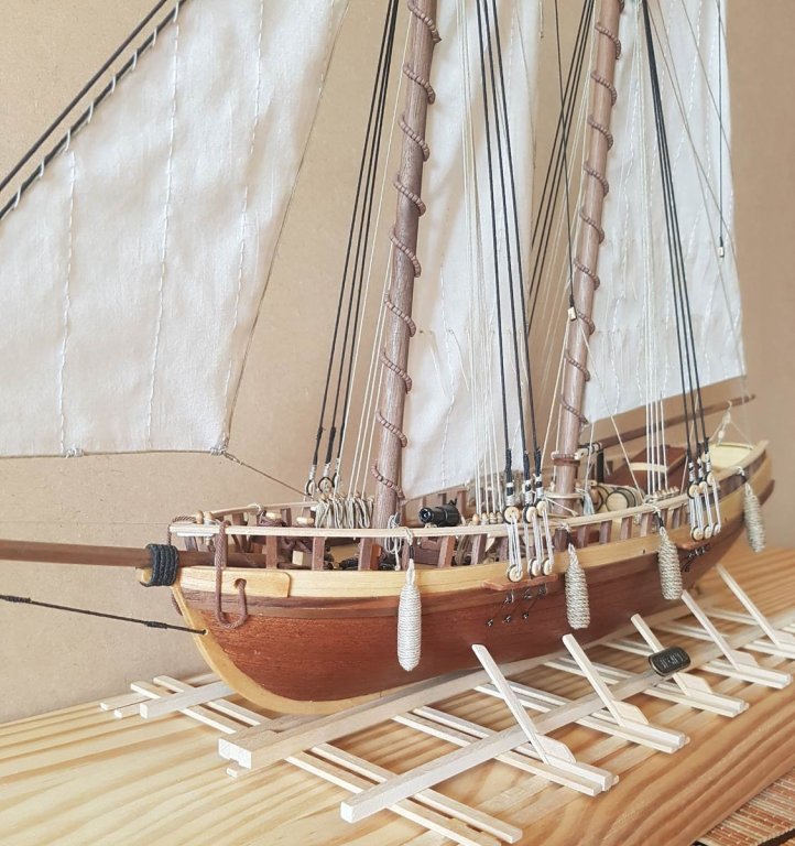
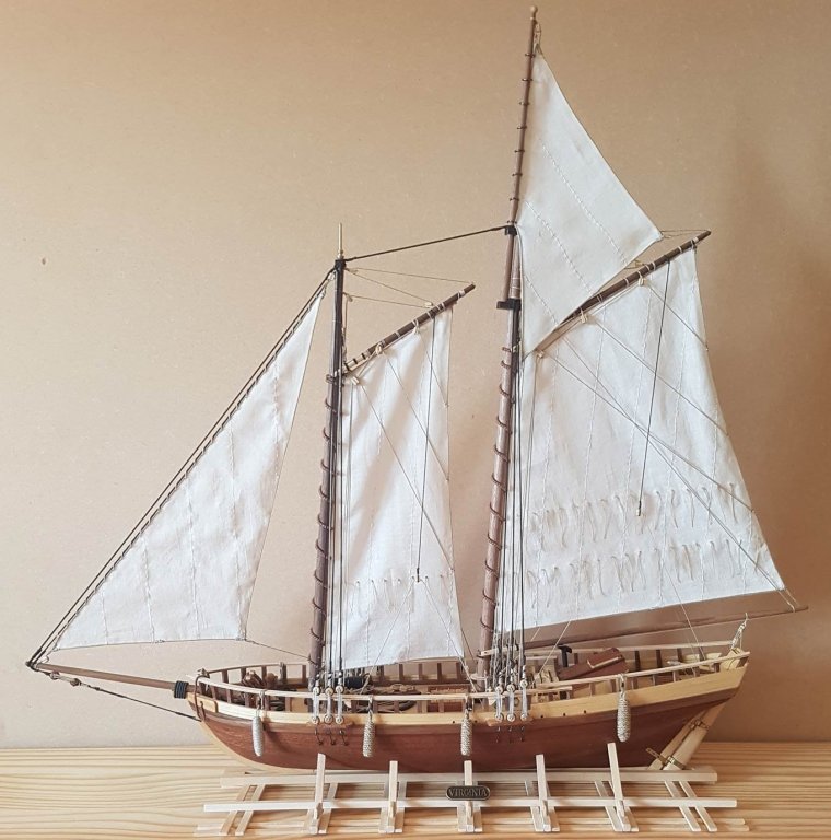
Hello all, and thanks for the comments and likes throughout this log. As promised here are the pictures of the finished model. This has been a fun build, even though it has taken three years! This kit is an interesting introduction to wooden ship building, especially for someone who is used to step by step plastic models. It is a real shame that this is a kit of a “boat that might have been” rather that a real boat. Having said that it allowed me to do a bit of kit-bashing. I have made some really obvious schoolboy errors, like the stitching on the sails and the use of poor materials in the chainplates. The kit instructions are poor when it comes to the rigging so I had to learn rigging from scratch - not easy when it seems like a foreign language. However, I’m glad I chose this kit as my first, I have learnt a lot about ships and shipbuilding and will stand me in good stead when building my next model, and eventually my ambition of building the Bounty. I hope you have enjoyed reading this log, and please, if you have any criticism let me know - its all a learning experience. Cheers Paul


- 50 replies
-
- 13
-
-
- virginia
- artesania latina
- (and 2 more)
-
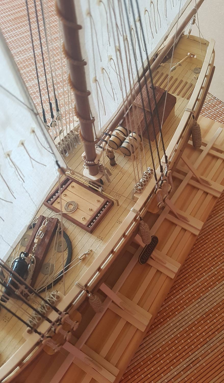
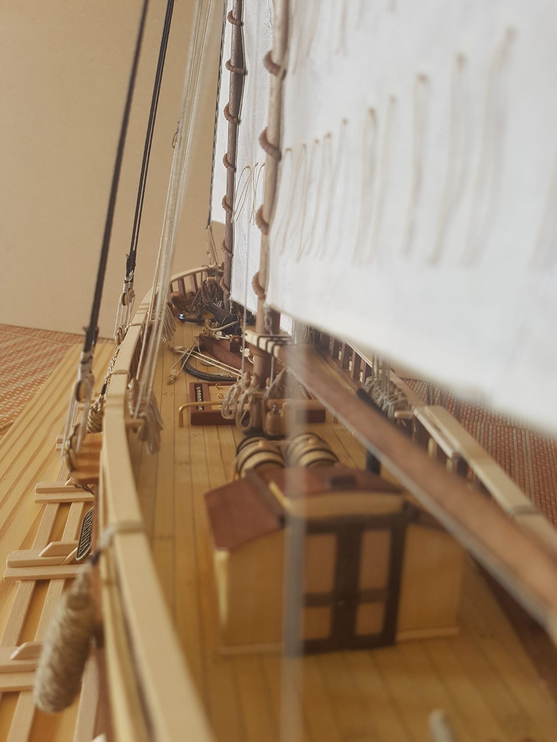
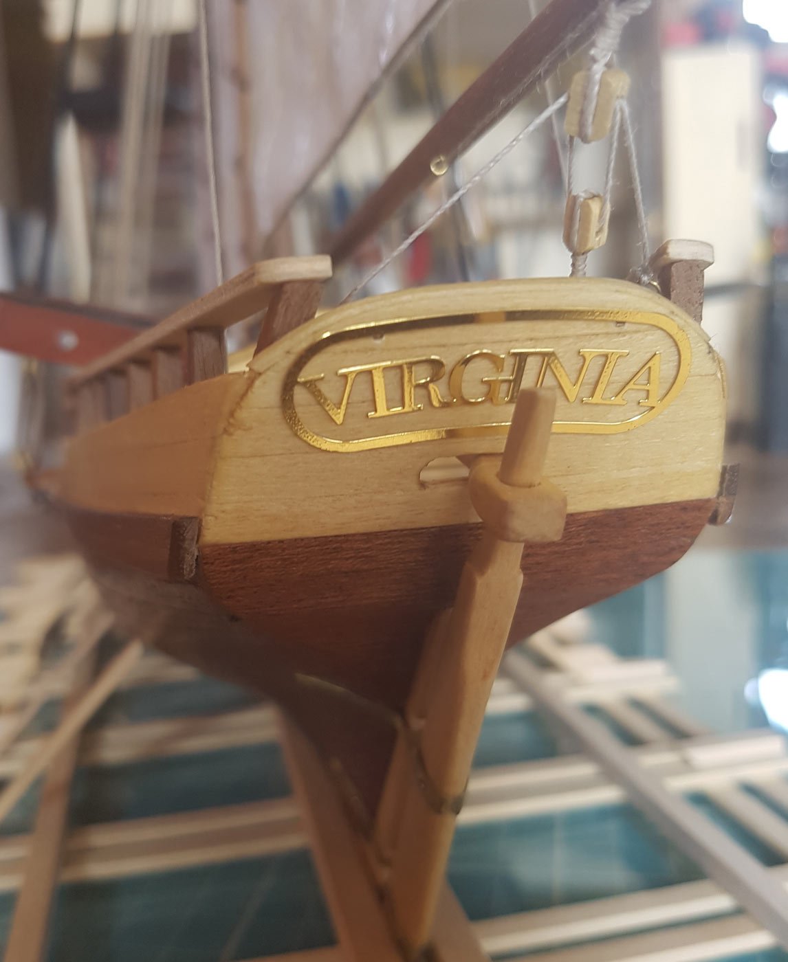
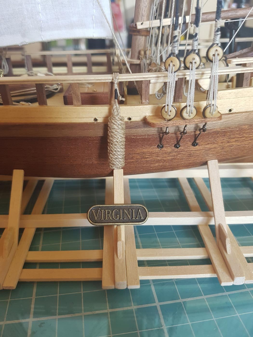
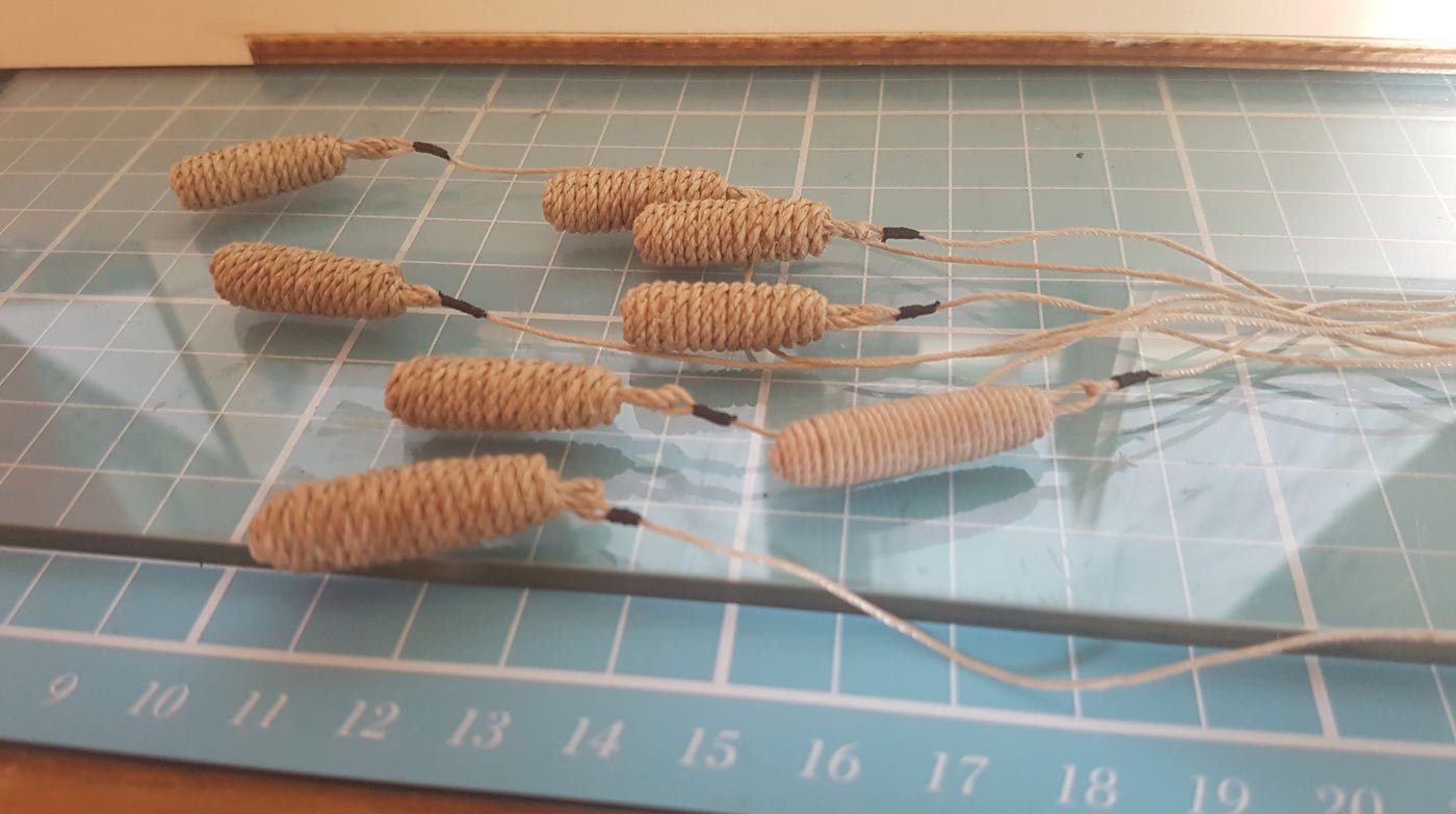
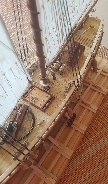
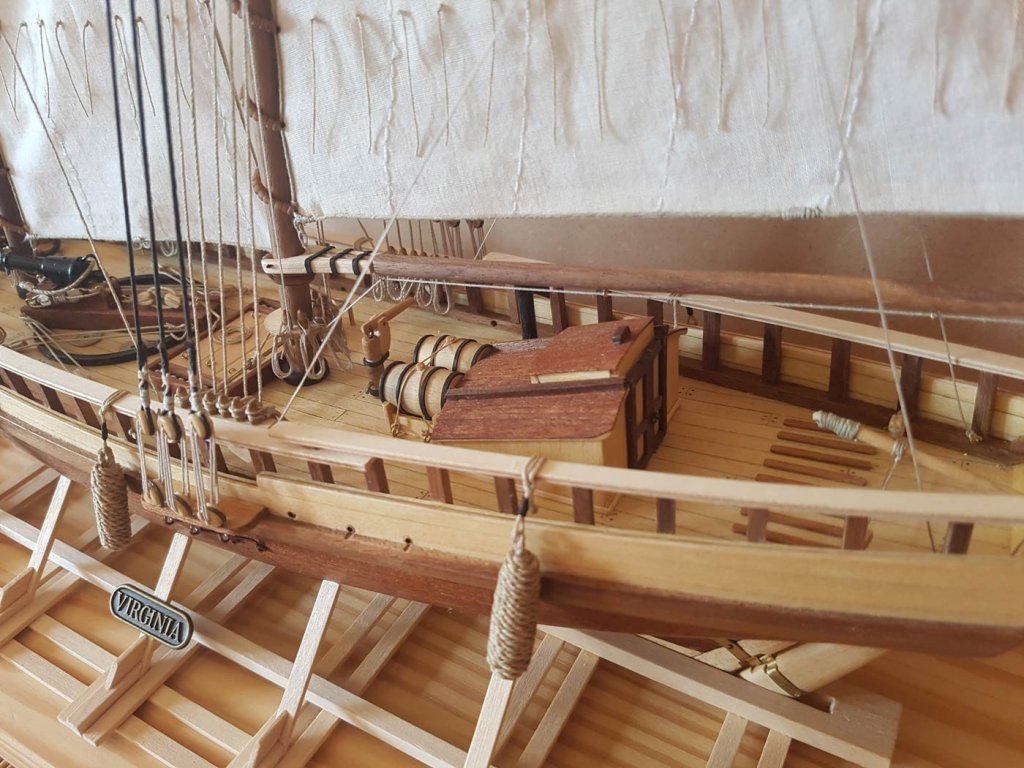
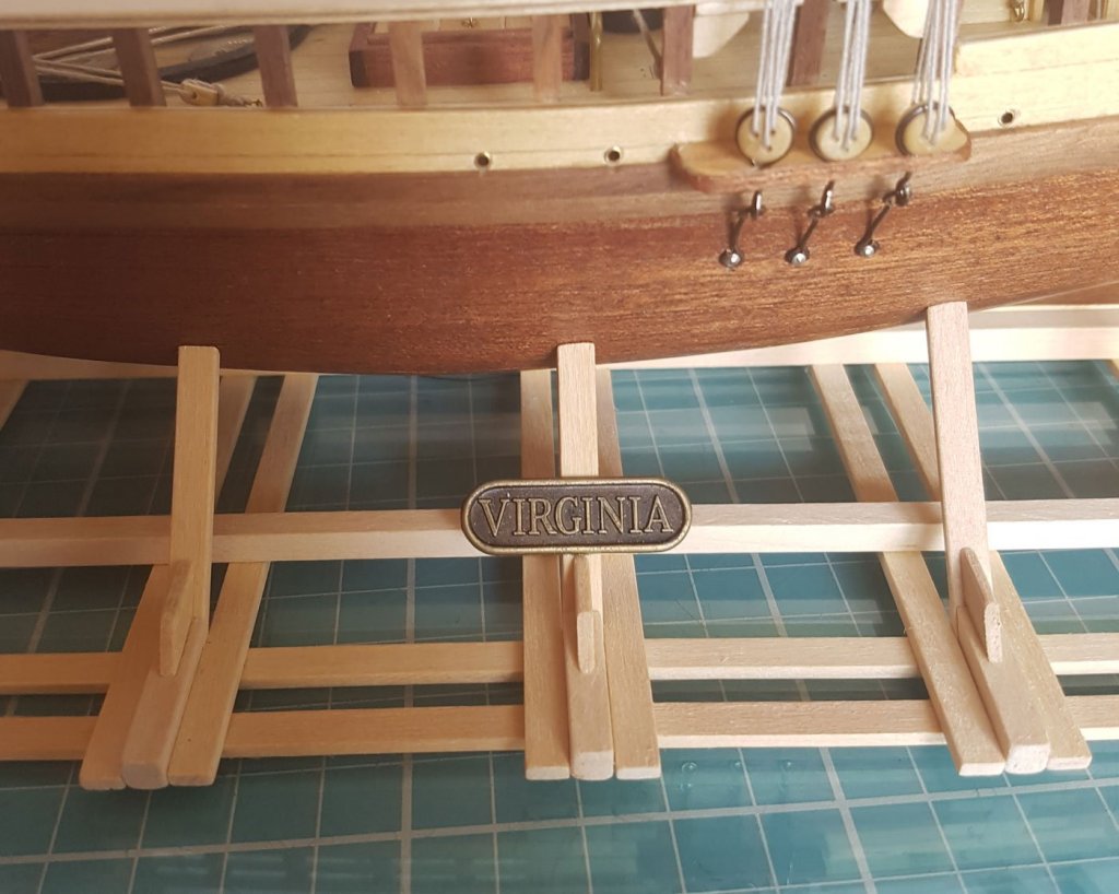
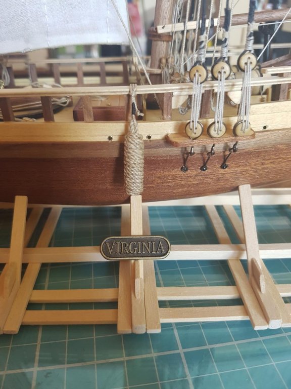
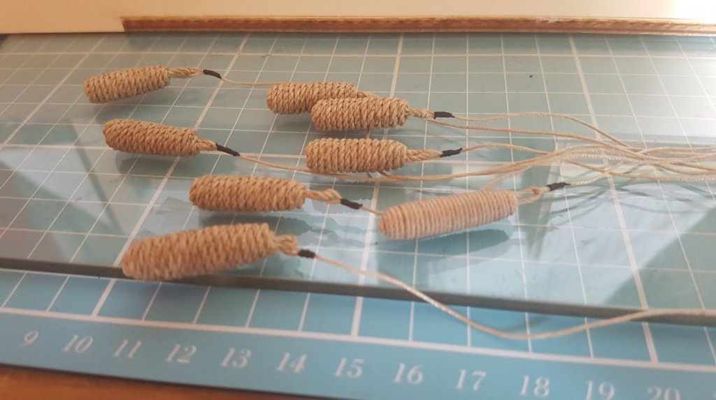
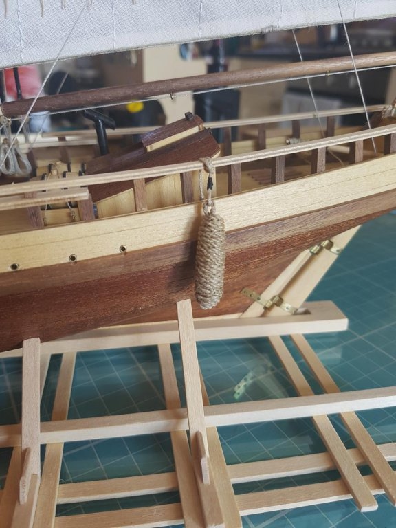
The final; The last steps have been completed; The nameplate on the stern of the boat; (needs repositioning to cover the holes drilled for the horse) The nameplate had already been fixed to the stand - both nameplates came with the kit; I read on here a while ago about how to make fenders, so I thought I would add some to the boat. I wrapped some coarse rigging line around a shaped dowell. I cant remember the author of the article on here but whoever you are a huge thanks! The fenders rigged up (I had always thought that these were called bouys) And fixed onto the boats rail with a Fishermans Bend (Anchor Bend), although my knots book informs me that it is not actually a Bend but a Hitch. The completed Boat; I have taken more pics which I will add tomorrow along with my thoughts and conclusions on this build. Cheers Paul


- 50 replies
-
- 8
-
-
- virginia
- artesania latina
- (and 2 more)