


hof00
-
Posts
1,655 -
Joined
-
Last visited


-
 hof00 reacted to a post in a topic:
Flying Fish by Rick310 - Model Shipways - 1/96
hof00 reacted to a post in a topic:
Flying Fish by Rick310 - Model Shipways - 1/96
-
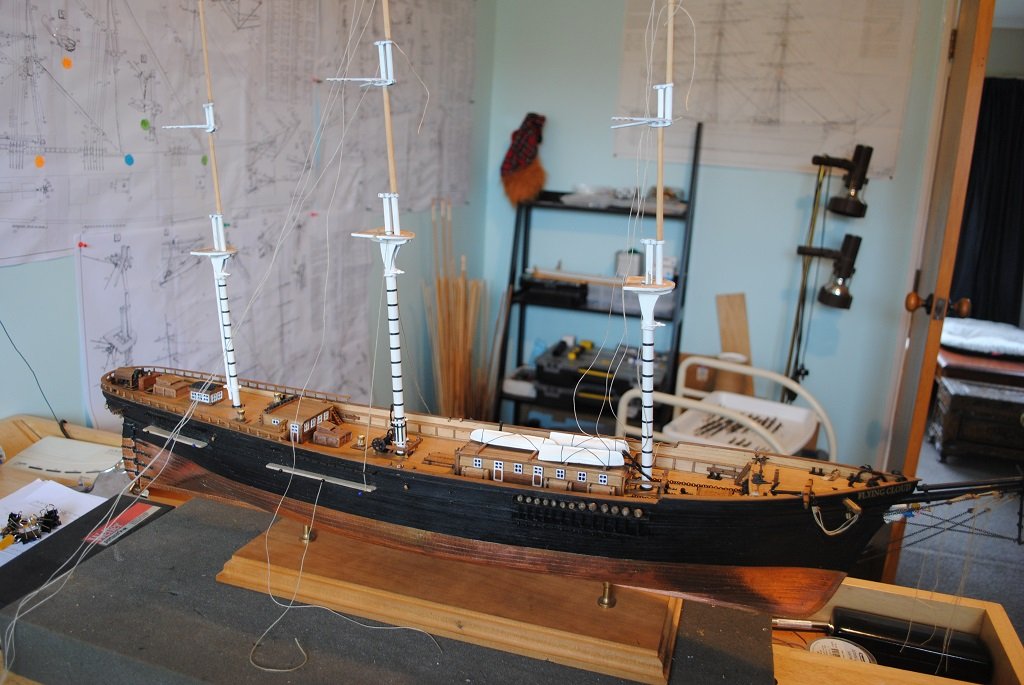
 Hi All, More "Channel" progress, sorry about that.... 🙂 Anyway, Channels/Chainplates pretty much complete, just a few "Tweaks," some tiny applications of CA and Paint. (I am pretty relieved to see the back end of these, soonish. (I also took the opportunity to clean up the Hull Plating.)) I am unsure of wots next, I thought I'd have a go at "Prototyping" the three Main Tops for Fairlead drilling. No matter what, there's plenty to do.... 🙂 Comments/critique always welcome. Cheers....HOF. Photos:
.thumb.jpg.c1c022cb619650059563a8612434e5b1.jpg)


.jpg.d54242e08553cf669af1b94c36f0aa52.jpg)
-
hof00 reacted to a post in a topic:
Endeavour by Bolsoy - Amati - 1:35 - J-Class Yacht
-
petervisser reacted to a post in a topic:
Flying Cloud 1851 by hof00 - Mamoli - 1/96 - American clipper
-
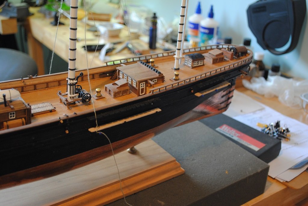
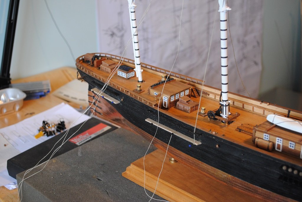
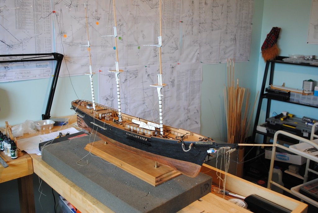
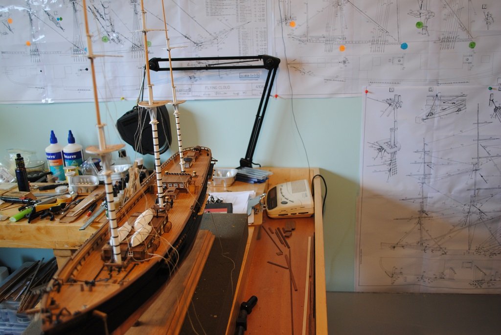
Hi All, Small update yup Channels again....😗 Main and Stern Lower Channels constructed and pinned on. Mainmast stepped temporarily to get angle of Chainplates worked out. (I "Notched" the Channels this afternoon, a couple of "Notches" need to be filled and moved slightly.) I decided to temporarily Step the other Masts to gauge if additional work is needed to strengthen the Mast "Steps." As it turns out, these will need some attention to make the Fore and Main a little more "Rigid." (Not today 🙂) Looks more like a Ship with the Masts on. (They are now removed.... 🙂) Most Chainplates, 62, constructed, only 10 to go. Cheers.... HOF. Photos:
- 203 replies
-
- 1
-
-
- Flying Cloud
- Mamoli
- (and 1 more)
-
hof00 reacted to a post in a topic:
Flying Cloud 1851 by hof00 - Mamoli - 1/96 - American clipper
-
aaronc reacted to a post in a topic:
Flying Cloud 1851 by hof00 - Mamoli - 1/96 - American clipper
-
aaronc reacted to a post in a topic:
Flying Cloud 1851 by hof00 - Mamoli - 1/96 - American clipper
-
aaronc reacted to a post in a topic:
Flying Cloud 1851 by hof00 - Mamoli - 1/96 - American clipper
-
aaronc reacted to a post in a topic:
Flying Cloud 1851 by hof00 - Mamoli - 1/96 - American clipper
-
aaronc reacted to a post in a topic:
Flying Cloud 1851 by hof00 - Mamoli - 1/96 - American clipper
-
aaronc reacted to a post in a topic:
Flying Cloud 1851 by hof00 - Mamoli - 1/96 - American clipper
-
aaronc reacted to a post in a topic:
Flying Cloud 1851 by hof00 - Mamoli - 1/96 - American clipper
-
aaronc reacted to a post in a topic:
Flying Cloud 1851 by hof00 - Mamoli - 1/96 - American clipper
-
aaronc reacted to a post in a topic:
Flying Cloud 1851 by hof00 - Mamoli - 1/96 - American clipper
-
hof00 reacted to a post in a topic:
HMS Warrior by Ian B - Billing Boats - 1/100
-
Hi All, Fore Channels complete? (Maybe a paint touch-up here and there.) So, now I have done the Fore Channels, I feel a little more confident that I have an idea of what I want to achieve. The only take-away from this assembly is that I won't be using "Blackening" solution, it stained the Deadeyes a bit, paint is better for these, the Blackening does not like the solder, and the Deadeye Strop is gaining a good patina after a few days anyway. I guess I am o.k. with my work thus far. Next will be the Main Channels/Chainplates and I have been busy making a bunch of Chainplates. (Low impact work 🙂) You'll have to excuse my grubby fingerprints on the Plating; I'll polish the Hull once I have completed Channel/Chainplate works. 🙂 As Rick310 stated, the Chainplates blend in, yup, they do. Only the Camera Flash picks them out. That's me for the mo. Cheers.... HOF. Photos:


-
Thanks Rick.
-
hof00 reacted to a post in a topic:
Flying Cloud 1851 by hof00 - Mamoli - 1/96 - American clipper
-
Hi All, Another Channel/Chainplate update I am afraid. Started last night with the Port side utilizing my Channel "Spacer." So, with a modicum of success, this morning, I decided to de-construct the Starboard side. An additional pin in the center of the Lower Channel fixed the "Bowing" issue. Spacer inserted, Chainplates were rescued where possible, bent and pinned to the Hull. (I only had to make two additional Chainplates. 🙂) I also made a very simple Jig for the initial bend for the Lower Channel. I decided on an angle of 18' At least all Chainplates are now more consistent. I am now a bit happier with the Starboard side. Once Channel Caps are fitted and all painted it should look the part.... Tomorrow, I'll finish the Port Side, Fore Chainplates and have a think about attaching Channel Cap-strips. (1.5 X 1.5mm Walnut) Cheers....HOF. Photos:
- 203 replies
-
- 2
-
-
- Flying Cloud
- Mamoli
- (and 1 more)
-
Hi All, Small update: Starboard Fore Channels/Chainplates, (Raw), Pinned in place. A bit of a learning process for me. (I may redo these, well probably.... 🙂) Some takeouts: Lower Channel needs at least 3 pins along its length Slots for Chainplates need to be a tad deeper Spacer required between Channels to prevent bowing as Chainplates are installed Need a more accurate drilling/cutting method for Chainplates I need to make up some more Chainplates before having a go at the Fore Port side. Anyway, enough for the mo. Cheers.... HOF. Photos:


-
Hi Ian, That's a rather large Hull!! Several years ago, I remember a build Log for this. (Can't recall where, sorry.) Anyway, the builder ran out of Decking Planks/Material.... I guess be judicious with the "Waste." Cheers....HOF.
-
hof00 reacted to a post in a topic:
HMS Warrior by Ian B - Billing Boats - 1/100
-
Thanks Rick.
-
hof00 reacted to a post in a topic:
Flying Cloud 1851 by hof00 - Mamoli - 1/96 - American clipper
-
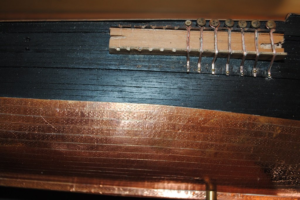
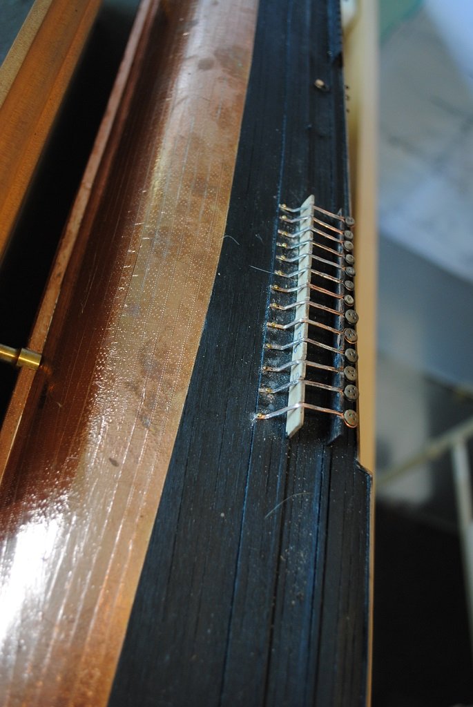
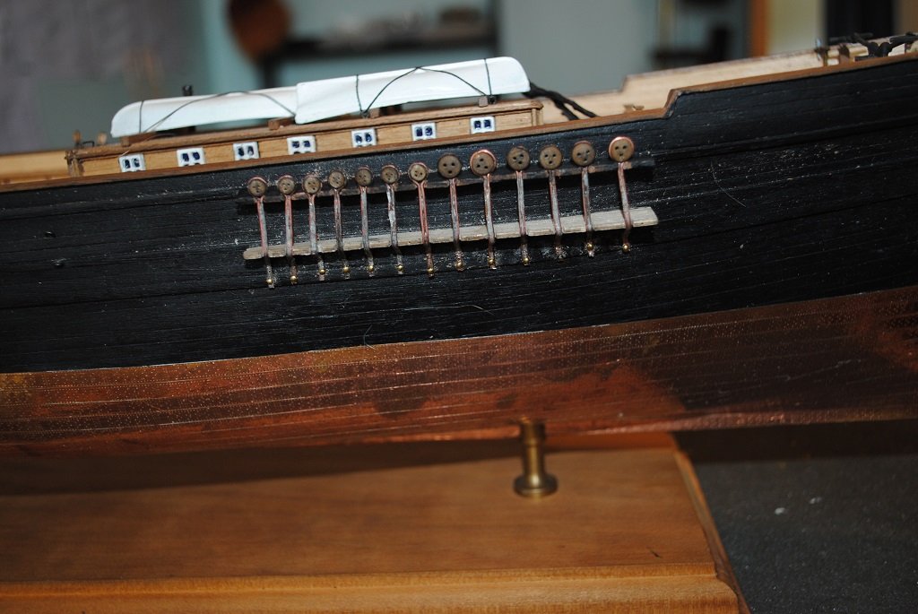
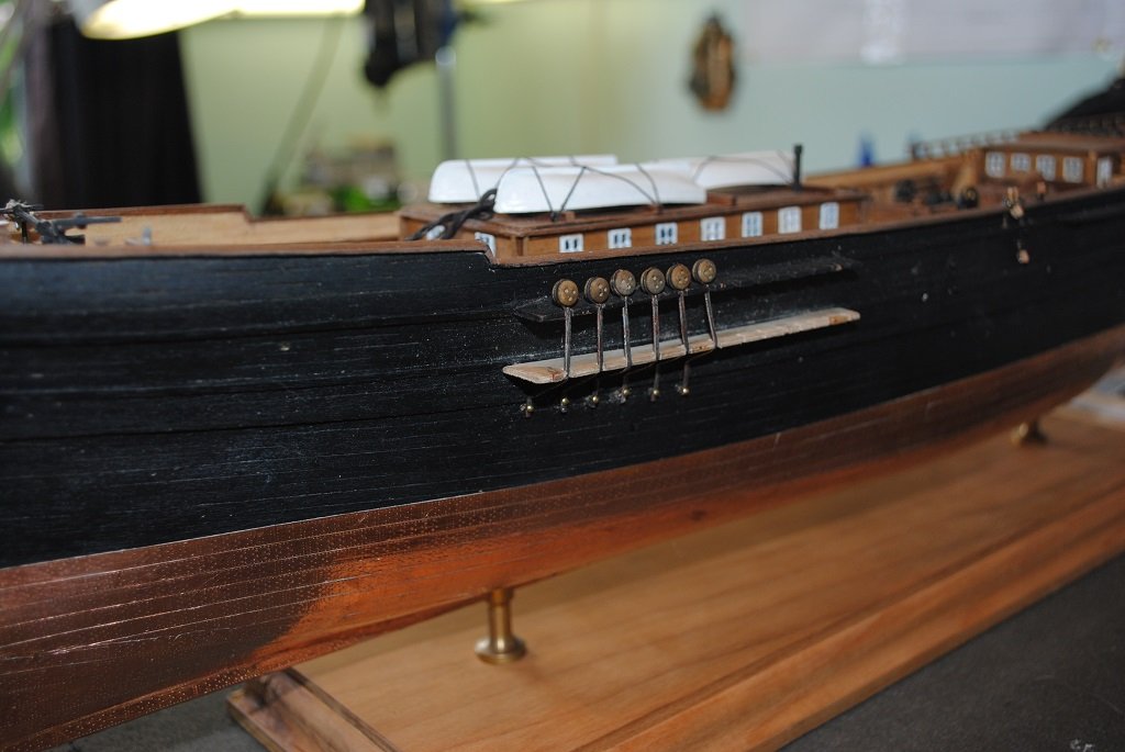
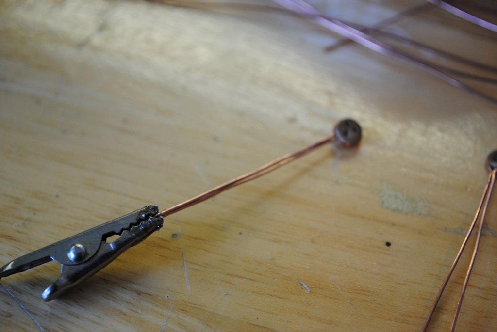
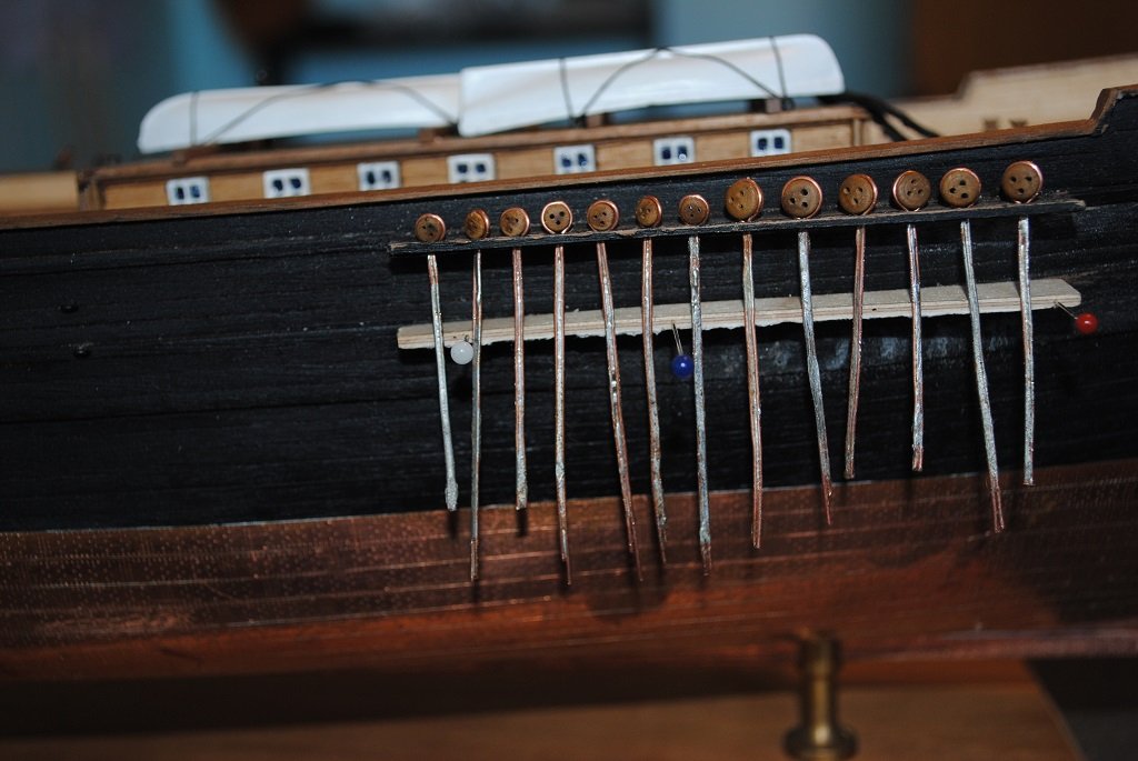
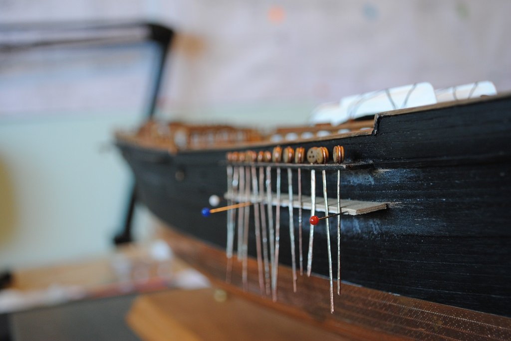
Hi Rick, Et All, I have taken a few photos to hopefully illustrate the method to the madness.... 🙂 At this time, I am concentrating on manufacture of the Chainplates and have not as yet "Notched" the lower Channels, nor have I Blackened/Filed/Drilled/Tweaked the Chainplates, so, you will have to imagine them fixed in place under the Lower Channel. Yes, the Chainplates are long at the mo., this will give me something to hold while "Manipulating." A big advantage, the Deadeyes sit "Flat" on the Channel, no nasty gap and in line. The method seems to work, a bit of time but very cheap, the wire was harvested from a bit of heavy electrical flex that I have in my Garage. The solder is 3% Silver, 1% Copper and 96% Tin with a "No Clean" Flux Paste. (I just have to be careful not to "Flame" the Deadeye. 🙂) Cheers.... HOF. Photos:


- 203 replies
-
- 2
-
-
- Flying Cloud
- Mamoli
- (and 1 more)
-
hof00 reacted to a post in a topic:
Flying Cloud 1851 by hof00 - Mamoli - 1/96 - American clipper
-
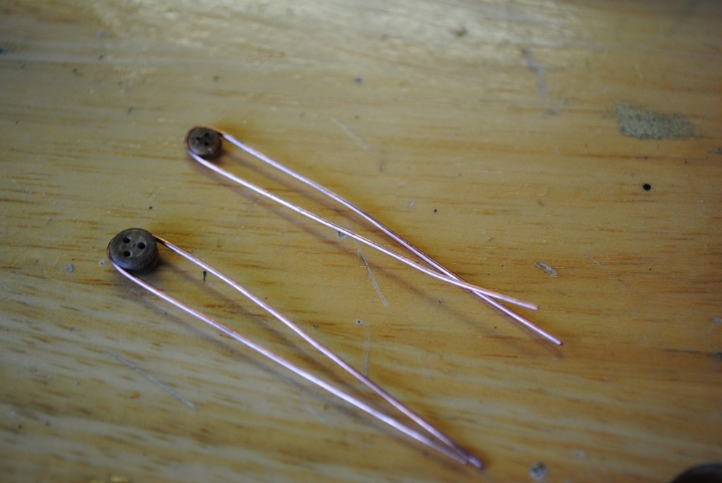
Hi Rick, Thank you for your kind comments and advice, appreciated. 🙂 I have started my Chainplate manufacturing process, ("Prototyping"), and have rescued my already constructed Lower Channels. Quite correct, I could not live with the kit Chainplates, they just did not look correct at all. (I had pinned the Fore Starboard-Side kit Chainplates, no good at all.) I have viewed your Flying Fish build on more than one occasion to see how you have done the Chainplate/Channel construction. I am utilizing 0.6mm Copper wire to form both the Deadeye Strop and Chainplate, pinch the wire together around the Deadeye and draw the wire, (Straight), together to form the Chainplate and run solder along the joint. (Chainplate) The only downside is no articulated Deadeye strop. Thus far I have almost completed the Fore Chainplates. I decided to use Copper wire as it is much more malleable especially around 3.0mm Deadeyes. (I did experiment with 0.6mm annealed Brass wire.) So, that's the state of affairs at the mo. and I'll get some photos when I have something to show for my time. 🙂 Cheers and Regards, Harry.
-
hof00 reacted to a post in a topic:
Flying Cloud 1851 by hof00 - Mamoli - 1/96 - American clipper
-
Hi All, Small update, no photos as yet. I have been struggling with the Chainplates for some time. I have decided to put the kit supplied parts in the "Too much trouble" basket and manufacture my own. This has the possibility of Lower Channels "Back in play" and this is what I am working towards.... (I am pleased that I kept these....) I have had many E-Mails with Daniel from Dusek Models to ascertain if he had replacements for Flying Cloud. (As it happens, he does, and they are an improvement in the form of Laser cut Aluminum.) I am still keeping my options open here, Daniel will review the Shipping cost in a couple of weeks but mentioned to me that the Shipping would probably be around 60.00 Euro. Hats' off to Daniel thus far for his efforts and Customer Service!! Tomorrow will be more "Experimenting" with Chainplates, and I'll post photos of development ideas in a few days. BTW All the best for everyone in 2026!! Cheers....HOF.
- 203 replies
-
- 2
-
-
- Flying Cloud
- Mamoli
- (and 1 more)
-
hof00 reacted to a post in a topic:
Cutty Sark by uscharin - Sergal - 1:78
-
Hi Rob, Thank you very kindly for your comments, much appreciated. I'll go with what I am comfortable with and with what "Prototyping" shows me. Even though not 100% I am hopeful the finished result will be acceptable. 🙂 Cheers and Regards, Harry.
-
Thanks Ron, I'm trying my best, my first at 1/96.... Tolerances are much "Tighter." 🙂 Yup, the "Table" has already proved its worth, edge drilling 1.5mm Lower Channels, even though they will not be used. Cheers and Regards, Harry.
-
Hi All, Lower Channel update.... I began by pinning the Fore Lower Channels to the Hull, easy enough. I then decided to make s Mock-Up, (Prototype), the Channels to fit the Chainplates. (I had already drawn this out....) As per my Drawing, the Chainplates were too short, esp. the Backstay Chainplates. Regarding the Backstay Chainplate with respect to the Lower Channels, the slot that I would have to cut in the Lower Channel to accept the Chainplate would leave about 1.5mm thickness where the Channel meets the Hull, far too thin. The kit utilizes a 2.0mm thick strip mounted on the Lower Rub Rail to simulate the Lower Channels. I now have to choose the way forward: Not really keen to construct/replace the Chainplates Lower Channels are not designed for this kit Not 100% accurate to leave Lower Channels off Photo, (On Box), looks just fine without Lower Channels Pushing ahead with Lower Channels risks breakages KISS - Keep It Simple Stupid Finally, what am I building this for? It is something that I enjoy, not a gift or presentation. My decision to omit the Lower Channels may upset some who are following this thread but that's just the way it is, constraints of the kit, engineering/design do not allow for modification. So, in conclusion, this model will be "Devoid" of Lower Channels I have tried and prototyped to install these items; I have to admit a small defeat.... With this attempt out of the way, I can concentrate on mounting/positioning Chainplates with only Upper Channels. In saying all of the Above, I will most probably install a 1.0mm strip on the lower Rub Rail where the Channel would have been, this will assist in Marking and positioning individual Chainplates and will be more in keeping to the kit design. Onward!! Many more challenges ahead.... 🙂 Cheers....HOF. Photos:


- 203 replies
-
- 1
-
-
- Flying Cloud
- Mamoli
- (and 1 more)
-
Arado Ar-196 by Ian B - FINISHED - PLASTIC - German seaplane
hof00 replied to Ian B's topic in Non-ship/categorised builds
Hi Chap, Looking good!! I missed the scale, 1/48? I have been looking, just looking, at thr Revell 1/32 version, re-released this year. I'll be interested to see the final result. Cheers.... HOF.
.jpg.343a5d50e5c5c6ce56fe9022fadebad9.jpg)
