HOLIDAY DONATION DRIVE - SUPPORT MSW - DO YOUR PART TO KEEP THIS GREAT FORUM GOING! (Only 44 donations so far out of 49,000 members - C'mon guys!)
×


JSGerson
-
Posts
2,618 -
Joined
-
Last visited
Content Type
Profiles
Forums
Gallery
Events
Everything posted by JSGerson
-

USS Constitution by mtbediz - 1:76
JSGerson replied to mtbediz's topic in - Build logs for subjects built 1751 - 1800
I have a lot of images of the Constitution, I mean a LOT of pictures. However strange it may sound, I do not have any images of the interior of the Commodore's pantry. I suspect, and this my opinion only, the Navy staff uses that small area for storage, something the public doesn't need to see. I have visited the ship at least 3 times, the last time was November 31, 2014 just before her last refit, but never got a private tour which would have allowed me to see things the general public did not have had access to. Had I joined the NRG sooner when they had one of their yearly conventions in Boston, I would have had that private tour. So sorry, no pictures of the interior of the pantry. I do have pictures of the tiller room where the steering cables hook up to the rudder should you want them. Jon -
USS Constitution by mtbediz - 1:76
JSGerson replied to mtbediz's topic in - Build logs for subjects built 1751 - 1800
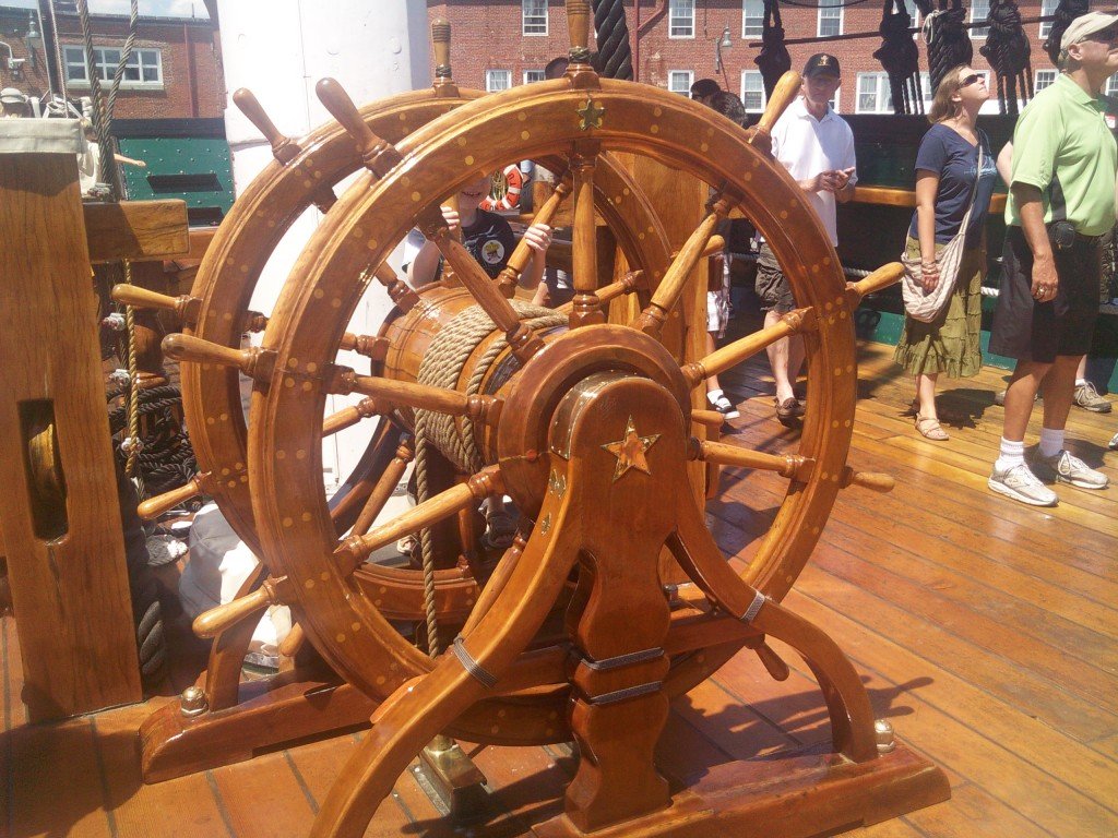
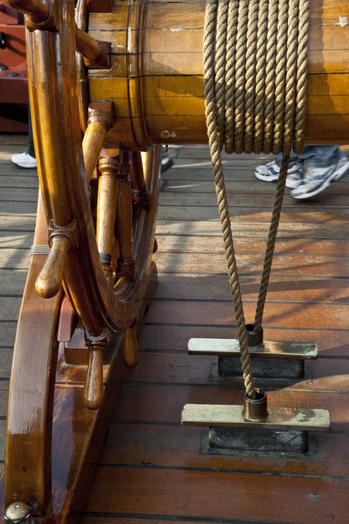
I assume that at some point you will wrap rope around the steering drum. That means the rope needs to pass through the deck. I didn't see any provisions for that. Should you rig the ship's wheel, here are some photos to help you do that.
-
USS Constitution by mtbediz - 1:76
JSGerson replied to mtbediz's topic in - Build logs for subjects built 1751 - 1800
Coming along very nicely Jon -
USS Constitution by mtbediz - 1:76
JSGerson replied to mtbediz's topic in - Build logs for subjects built 1751 - 1800
Nicely done, you make it seem so simple. Of course, it helps to have the proper tools, like a drill press sitting over a lathe. The metal rods work nicely too. They won’t snap and break at the merest glance. If you had absolutely no choice but to use wood, I would have recommended bamboo pulled through a drawplate. The bamboo fibers give added strength. That’s how I made my treenails for my Rattlesnake. Although that process is tedious and a pain, it works. Jon -
USS Constitution by mtbediz - 1:76
JSGerson replied to mtbediz's topic in - Build logs for subjects built 1751 - 1800
As usual, you blew right past me with the canopy frames. I am not a soldering wiz. I thought about using solder, but I have never done anything that complicated with it. You seemed to have figured it out. You didn't fabricate the frame's central ornament so that simplifies things. I'm still playing footsie's with my glued joints. Until the whole structure is assembled, one wrong move and I break a glued joint and it's one step forward and two back. This slows down my normal slow pace even further, but I'll persevere. Now that you are starting the ship's wheel, are you following anyone's method or are you "reinventing the wheel"😁? Sorry, I couldn't resist that quip. I don't know if you have any plan's for the wheel, so I have attached the US Navy plans for your convenience should you want to refer to them. Jon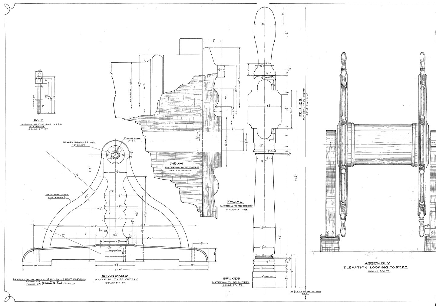

-
I wouldn't worry too much about whether the wire overlaps itself or not. Once you paint or blacken them, insert them into the bulwarks, and hook the gun tackle to them, they will all but disappear from from view or notice. Also they will be be in low light conditions and barely visible. I made mine the hard way, I silver soldered two eyebolts together because I didn't think to do it another simpler method. Jon
-
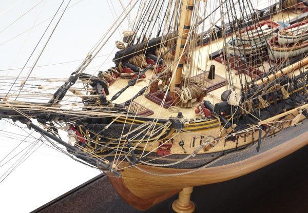
Marcus K - The original posting of Antczak's model images were originally on American Marine Models' website, but have since been removed. They have a memorial to Mark Antczak's memory which states in part: However, I have not been able to locate an original source for those images now. But all is not lost, I made a copy of them as well as Usetosail who posted them on his build log of the USS Constitution post No. 556. Here are all that I have have plus three additional photos that Usetosail did not post.


- 233 replies
-
- 5
-

-

-
- Model Shipways
- constitution
- (and 5 more)
-
USS Constitution by mtbediz - 1:76
JSGerson replied to mtbediz's topic in - Build logs for subjects built 1751 - 1800
As we have all learned, there is no easy way to make the canopies due to the fragility of the brass rods to hold their shape and all the required connection points. For me, the hardest point was figuring out how to handle the center hub. If you stack the rods as they cross each other, the structure becomes distorted. If fabricating a center hub where the rods meet at the same level, a jig must be designed so that the multi-joint can be soldered, glued, or mechanically connected in such a way that it is aesthetically appealing as well as strong enough to survive the installation process. This requires patience, tenacity, ingenuity, and it helps if you are a bit eccentric. Builders like xKen (Ken Forman) have the skills to solder and manipulate brass pieces. I came up with a mechanical method which seems to be working for me. It’s a bit out of scale, but it works. It looks like your method will work for you. Looking forward to seeing the finished product. Jon -
Like I original mentioned, I've never tried blackening brass to enhance the painting process, so I would do a test on a piece of scrap metal. Glad to be of help Jon
-
You might try pasting a narrow piece of paper across the joint on the bottom side of the frame to act as reinforcing holding the frame ridged. Once the grid is fastened to the frame and attached to the deck, the frame will be permanently supported. I had a thought about painting the hatch comings. In my limited experience, paint tends to slide as it is being brushed to smooth metal surfaces. Try blackening the brass a bit to add a bit of surface roughness for the paint adhere. This way you can add thin light coats of wood colored paint, and not clog up the grid openings. I've never tried this before; it's just a thought. Jon
-
Excellent research on the gun carriages to obtain authenticity for your model. It is for the reasons you encountered in the your quote above that use the hardwood, boxwood, for any wood component that requires precise edges. It may be a bit more expensive and not as readily available in hobby shops (but certainty available on-line), but is well worth it. If you have read my log closely, I indicated when and why I switched woods. Typically, if the wood is to be unpainted, stained, or I need those sharp edges even if painted, I'll use boxwood. In my Rattlesnake model, I used different color woods in lieu of paint (except for black. Ebony was called for but I used paint for reasons of availability, health (saw dust not healthy), and resistance to bending). Jon
- 233 replies
-
- 1
-
-
- Model Shipways
- constitution
- (and 5 more)
-
USS Constitution by mtbediz - 1:76
JSGerson replied to mtbediz's topic in - Build logs for subjects built 1751 - 1800
See, there is an advantage for going slow, now I got you to show me how it's done. Beautiful work on the stanchions and fife rails. Now if I can just set up my Dremel drill stand so it can perform this feat when the time comes. Jon -
Peter: As tricky as that companion way framework was, I did enjoy working it out. It was a nice puzzle. If I had access to the printed versions, I might have giving up and surrendered to the temptation to using a manufactured part, and where is the fun in that? Looking closely at my work, there were a lot of things that weren't as precise as I would have liked. Hopefully, I will do better this next time around. Unegawahya: I am just starting to work on the next canopy and feel much more confident, however I do plan on leaving one companionway closed with the grating on, and the canopy frames off. just to show the difference. The concept is relatively simply, but the execution can be tedious and delicate. Jon
-
Take a look at Jfinan's BJ build starting at Post 60, to help clarify the gratings for you. Jon
-
Peter, I still haven't found out who made those printed versions we saw earlier. If I do, I'll let you know. Jon
-
I love banging my head against the wall...I feels so good when I stop!😁
-
Thank you very much! Coming from you Mustafa, that means a lot!!! Jon
-
You made great progress especially on the windows openings. The window frames provided by the kit are not true to shape as they are distorted based on the foreshortened view from the side of the ship. This is why most of us had a problem using them and resorting to trying to fabricating them. I had so-so results. Looking forward to your future posts. One minor note, I appears your port holes are a little proud of the hull. They should be flush to the hull with only their "eyebrows" protruding. But I'm a detail nitpicker and unless one is aware of this fact nobody will notice or care. Jon
-
Thanks for the praise guys, now I have have to do it again, & again, & again, & again and be consistent about it.😬 Jon
-
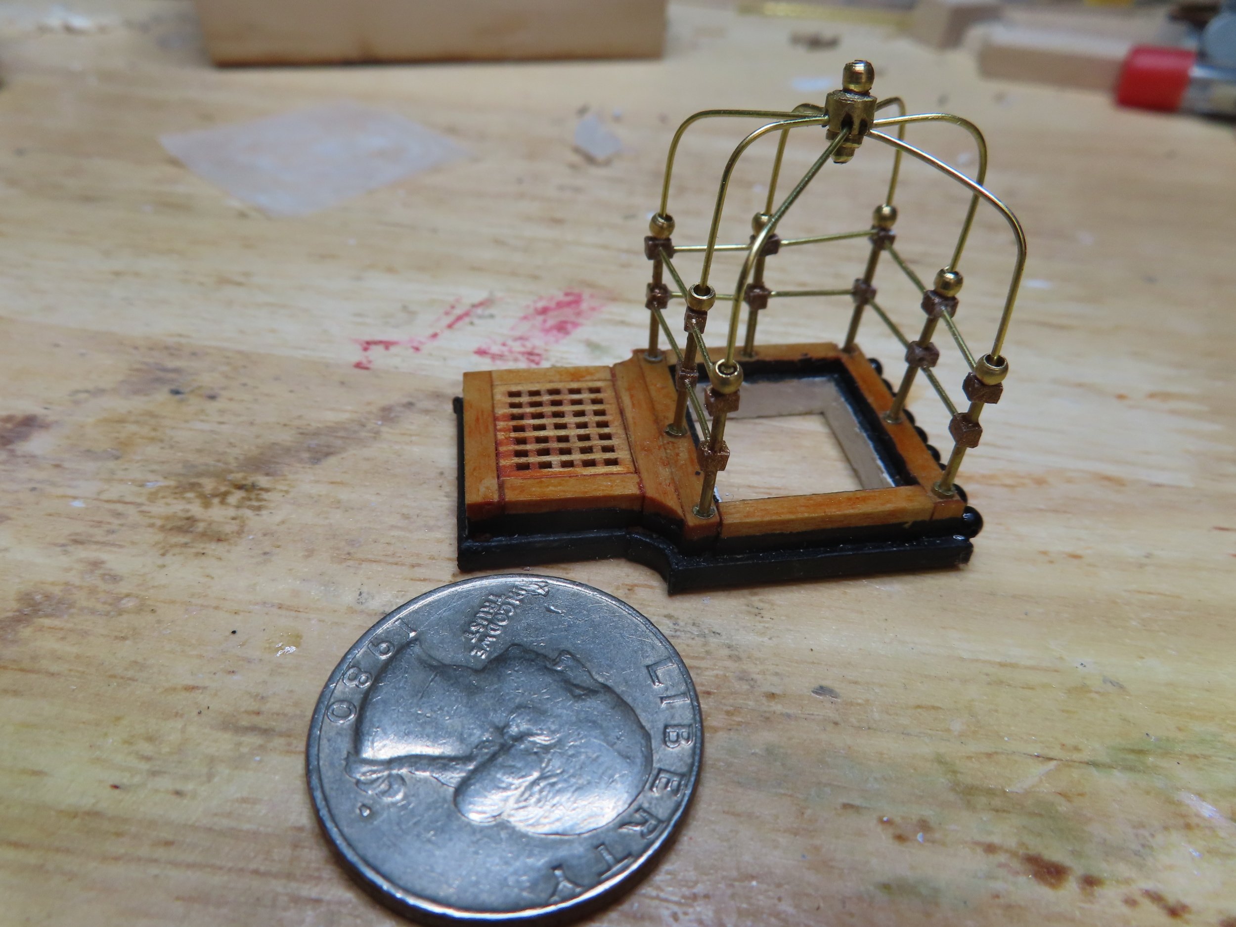
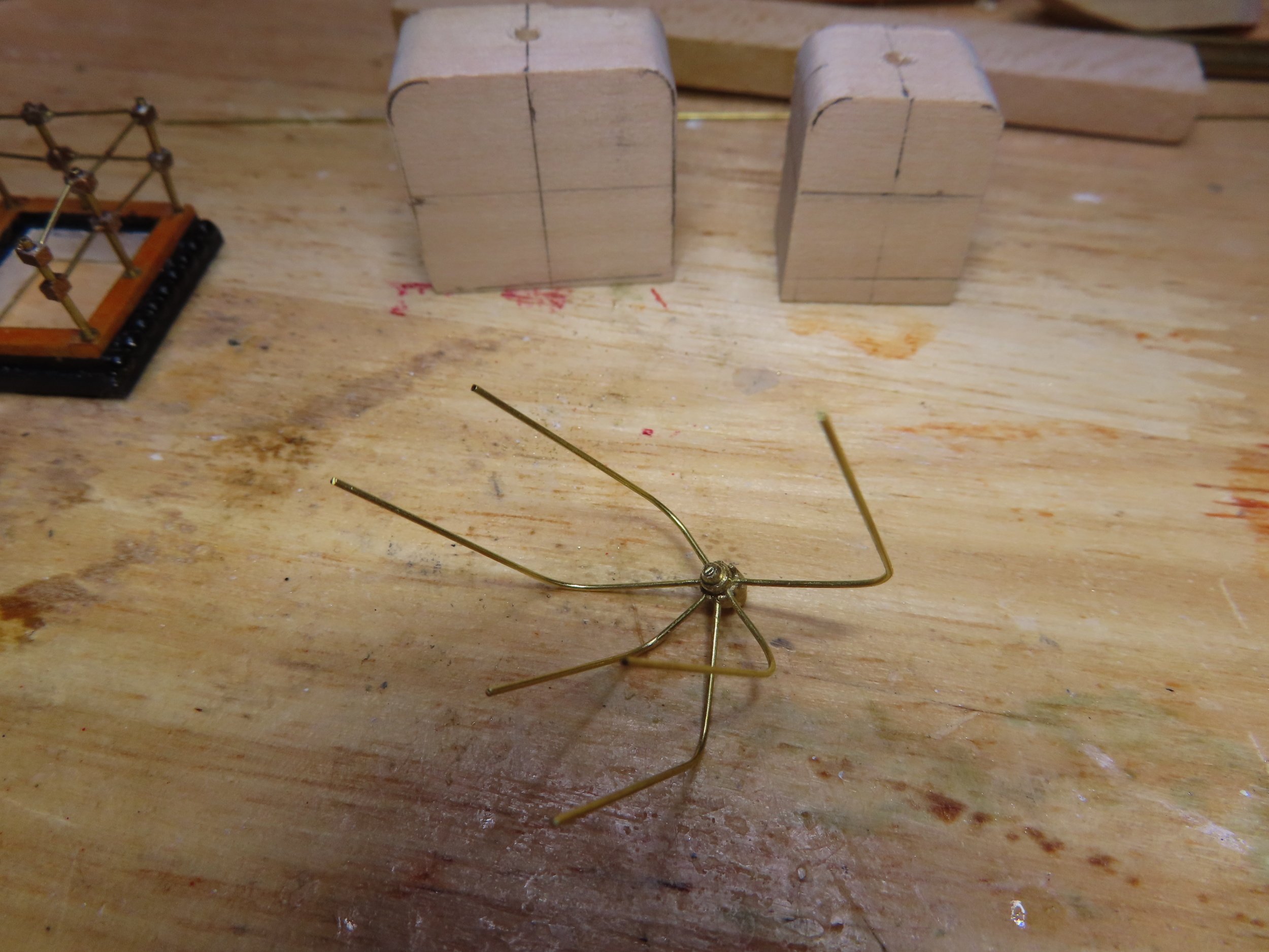
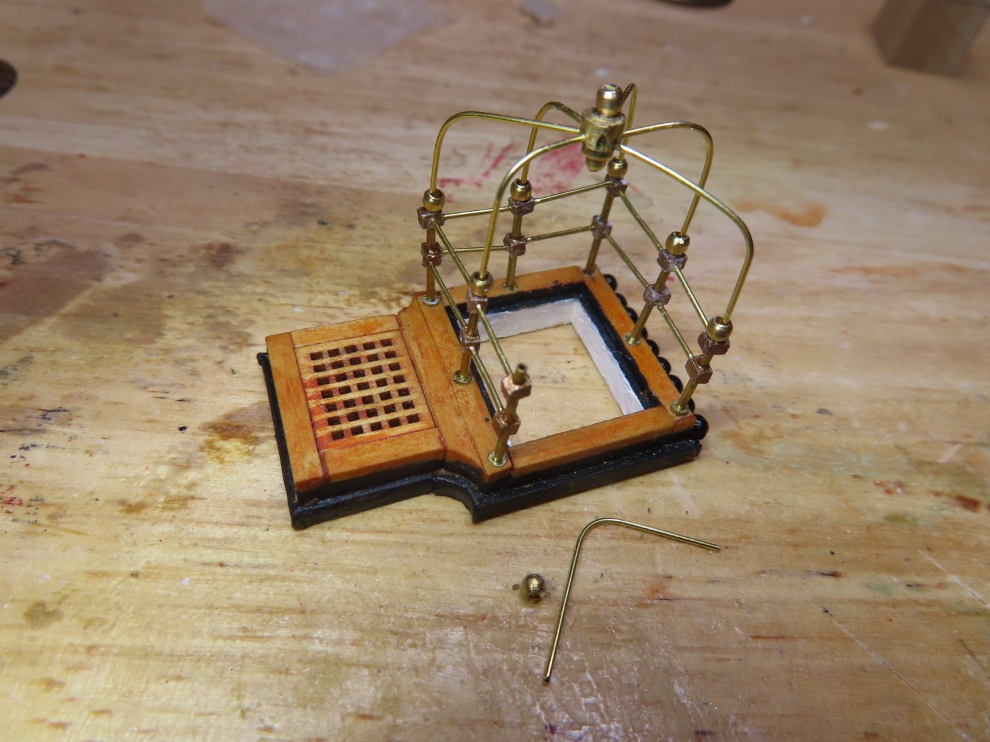
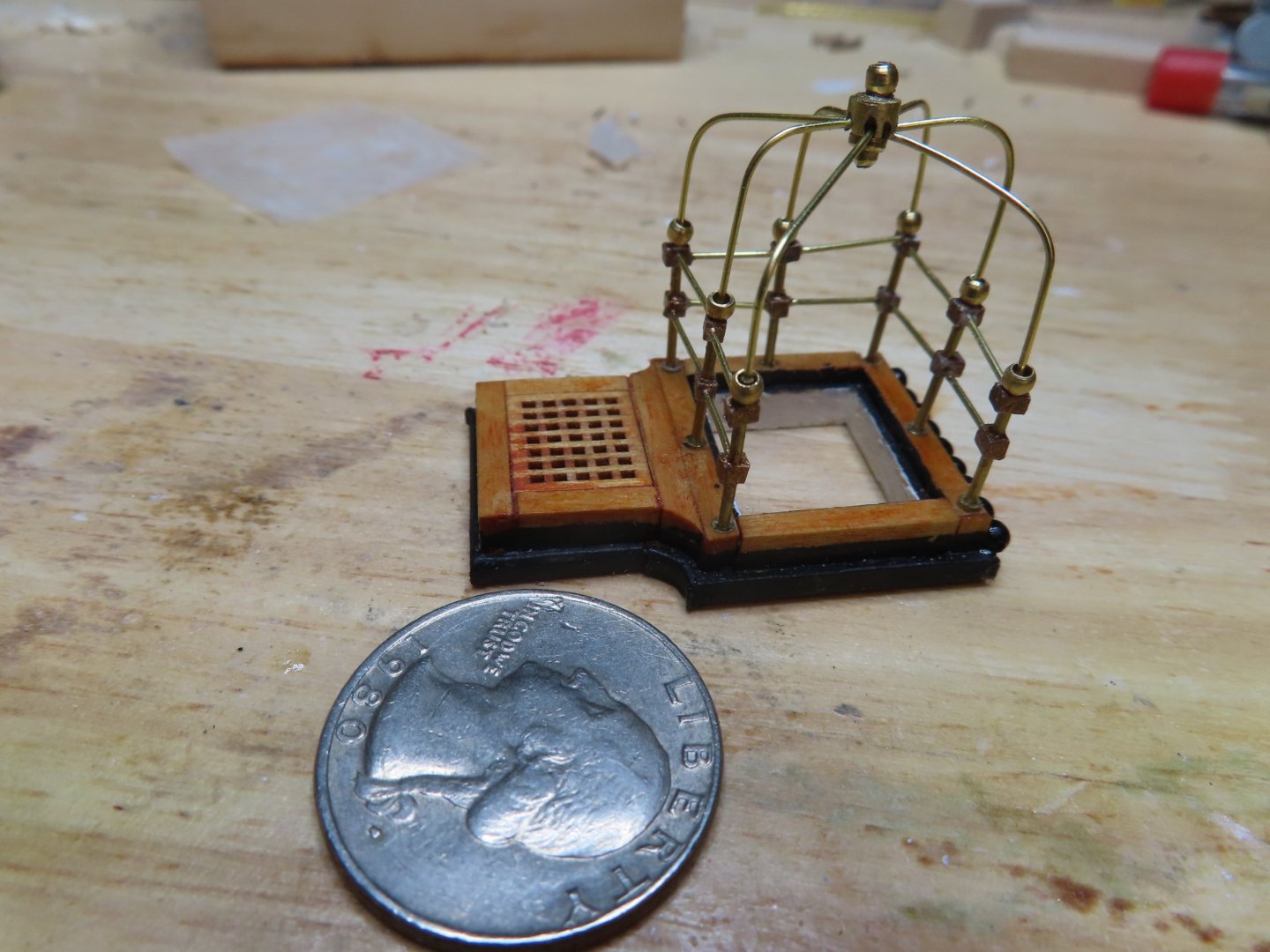
Attaching the “spider” to the stanchions went smoother than I had expected. The legs of the “spider” were trimmed and be approximately even with each other. Then a brass bead was added to each support and inserted into a stanchion, moving around the hatchway one by one in turn. The last support (unpaired) was cut to size from the “0.020” brass rod and added to complete the canopy. It’s not perfect, a little out of scale, and maybe a tad crooked, but it’s done. This one assembly took almost two months to complete. Now that I know what to do, hopefully the remaining four frames will go a little easier and quicker…maybe.
-
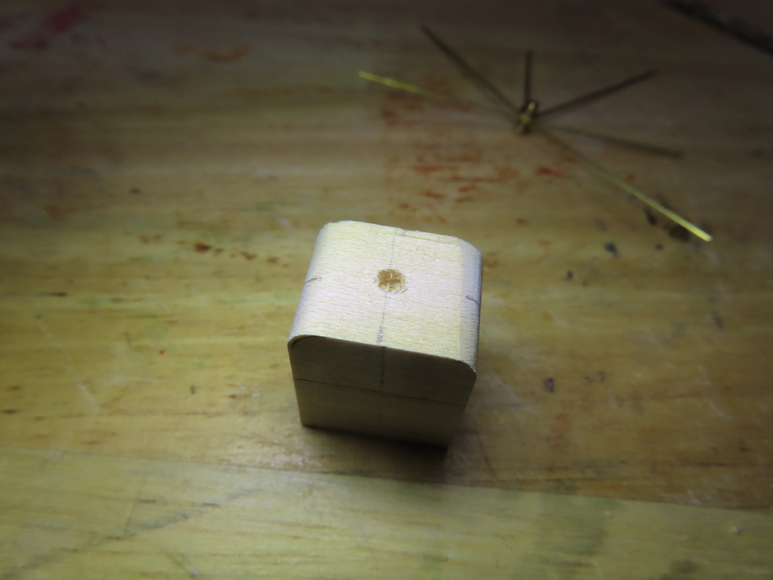
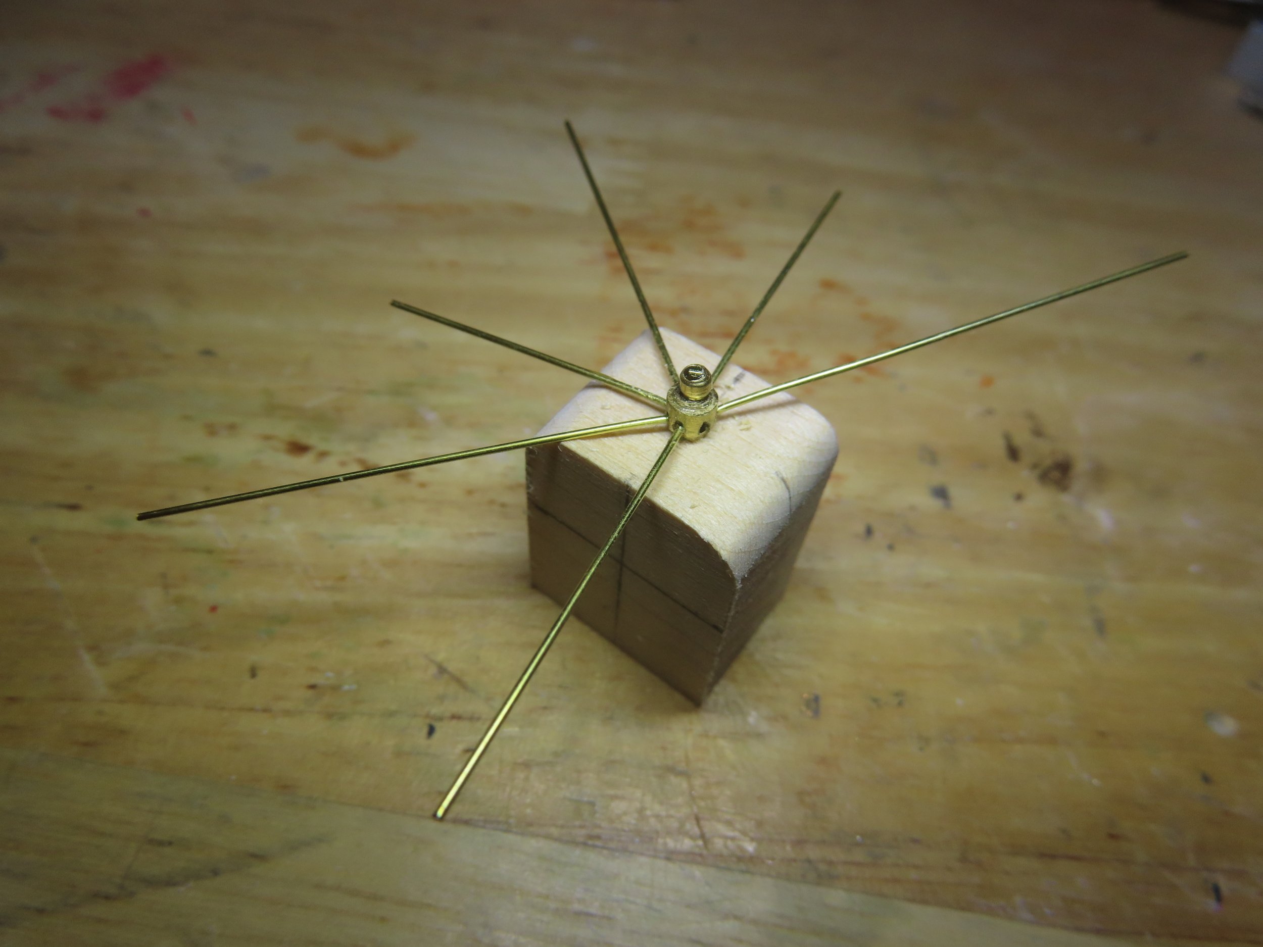
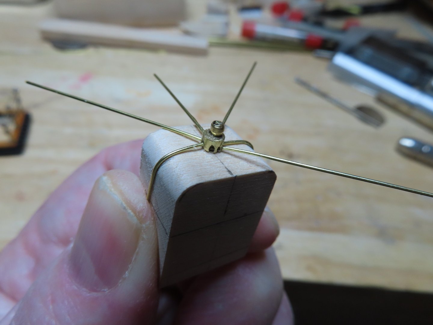
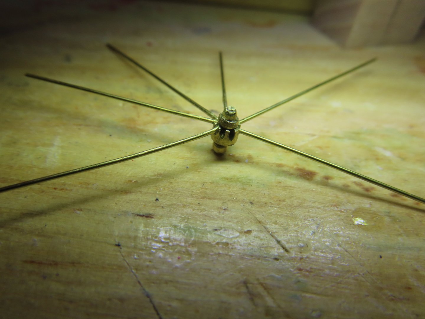
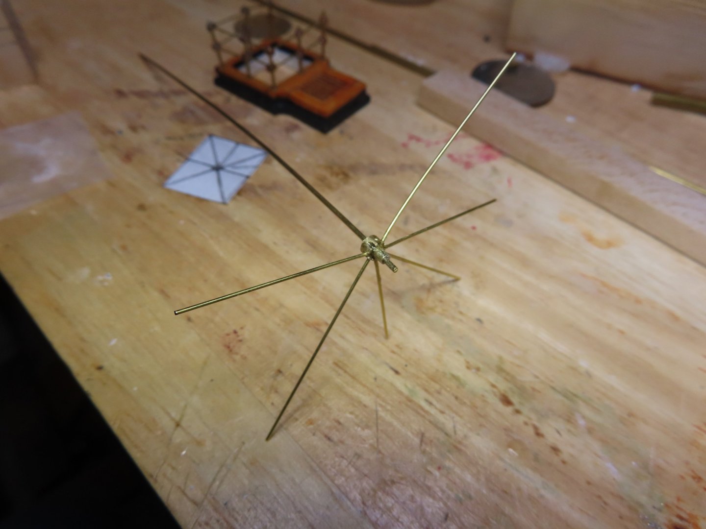
A 3/32” hole was drill into each of the two bending jigs to position the canopy hub. The canopy supports were easily bent which created a brass “spider.” Note, the 7th support remains to be fabricated.


-
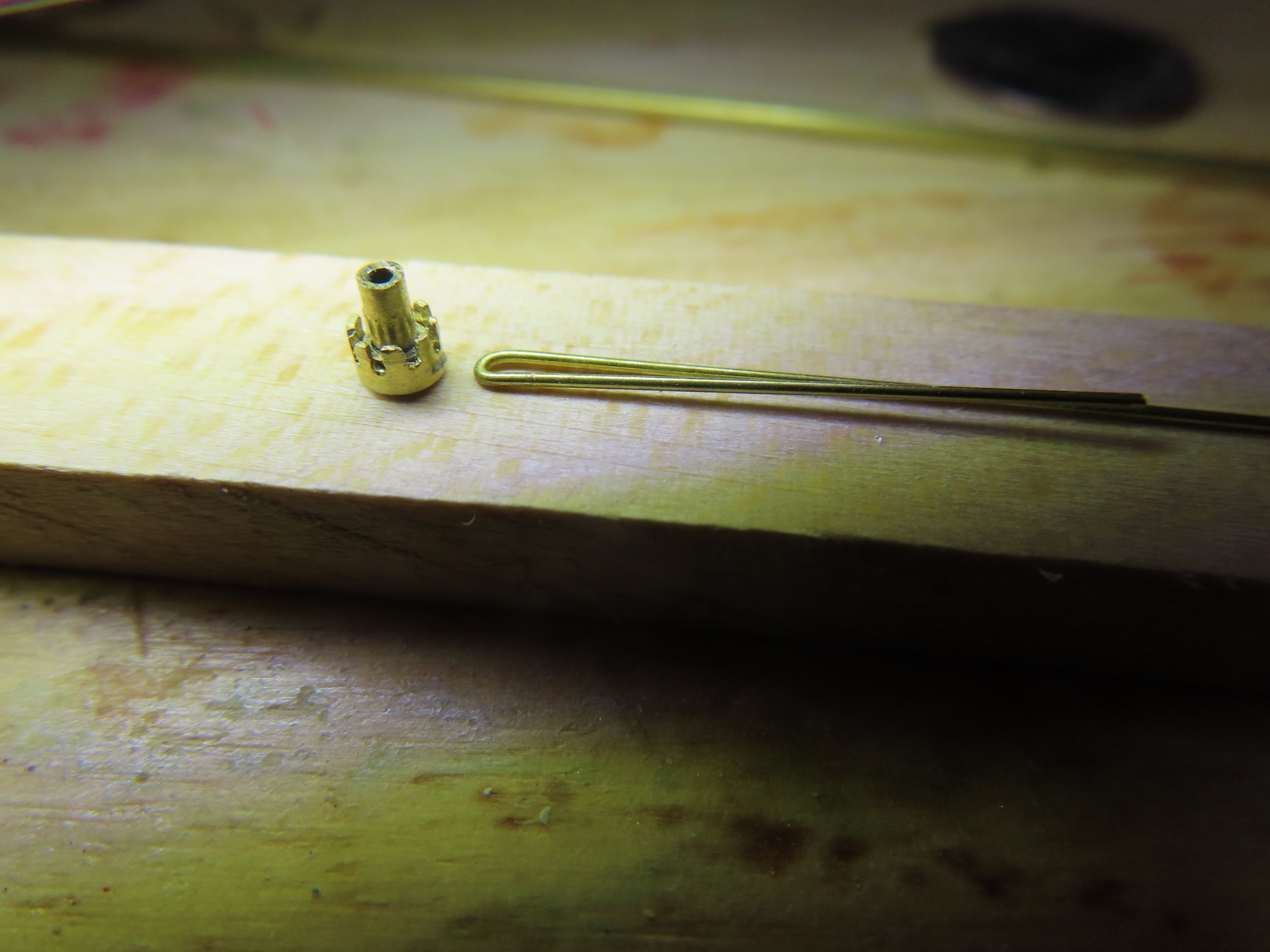
The assembly was cut off from the working “handle,” the ornamental top was trimmed, and the ornamental brass bead was glued to the bottom stem. The second photo shows assembly lying on the hatchway.
-
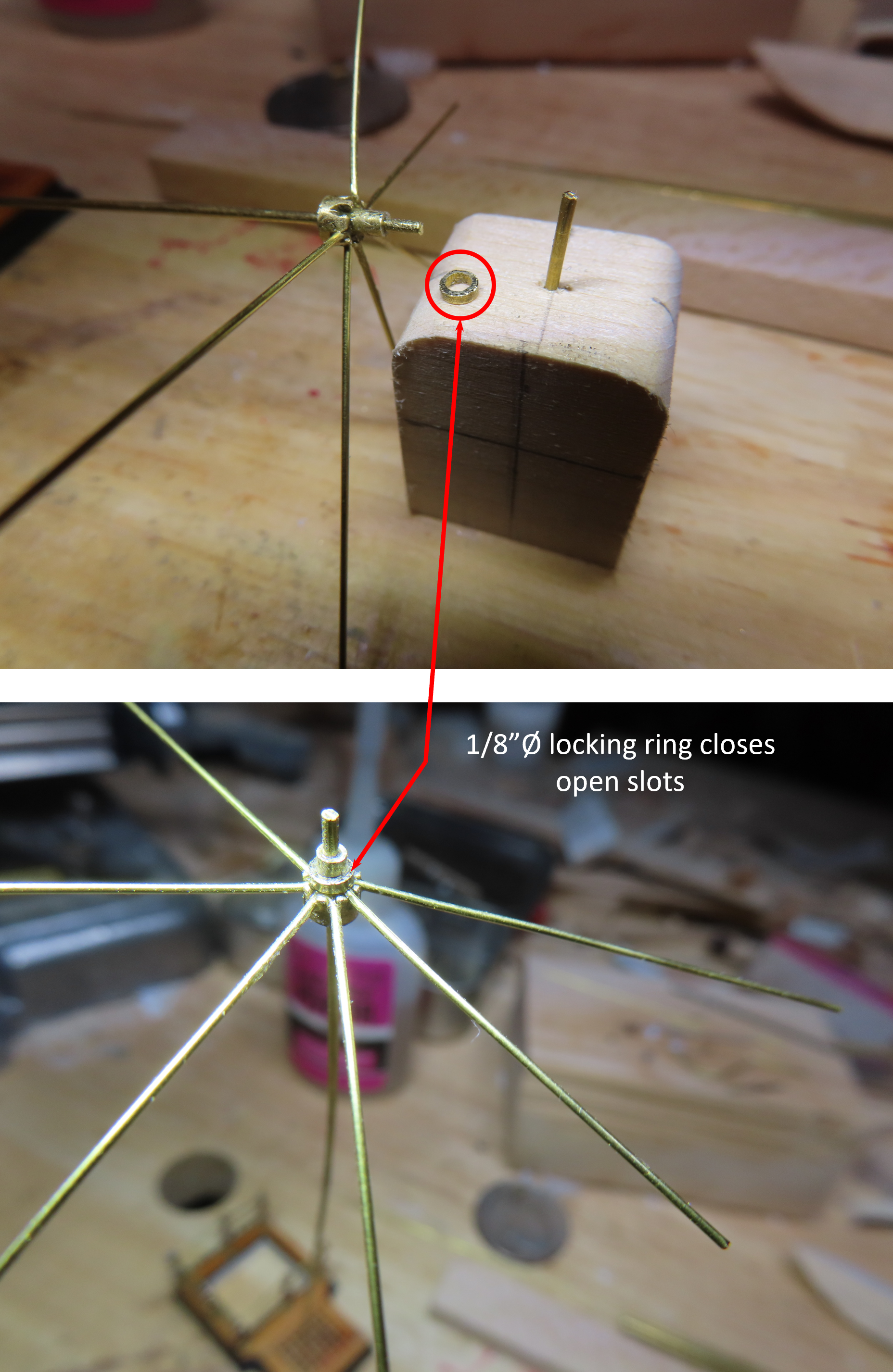
To complete the mechanical hub structure, a locking ring was cut from the 1/8ӯ tube and fitted over the slots converting the slots into holes and locking the supports to the hub.
-
A length of 2 3/8” 0.020” brass rod was cut and bent so that one leg was 1” and the other 1 3/8” for the two supports lengths of the frames. This is a bit more than was needed, but it is easier to cut off excess than extend a short leg. Three pairs or 6 supports were created, however, this canopy required 7 supports. The last support (non-pair) was planned to be added once the canopy was assembled. At that point the seventh support will slide into the remaining opening in the hub and be glued into place. A length of 1/16”Ø brass tube was inserted into the hub assembly as a “working” handle. As each pair of supports was added to the hub, it was secured by CA glue.
-
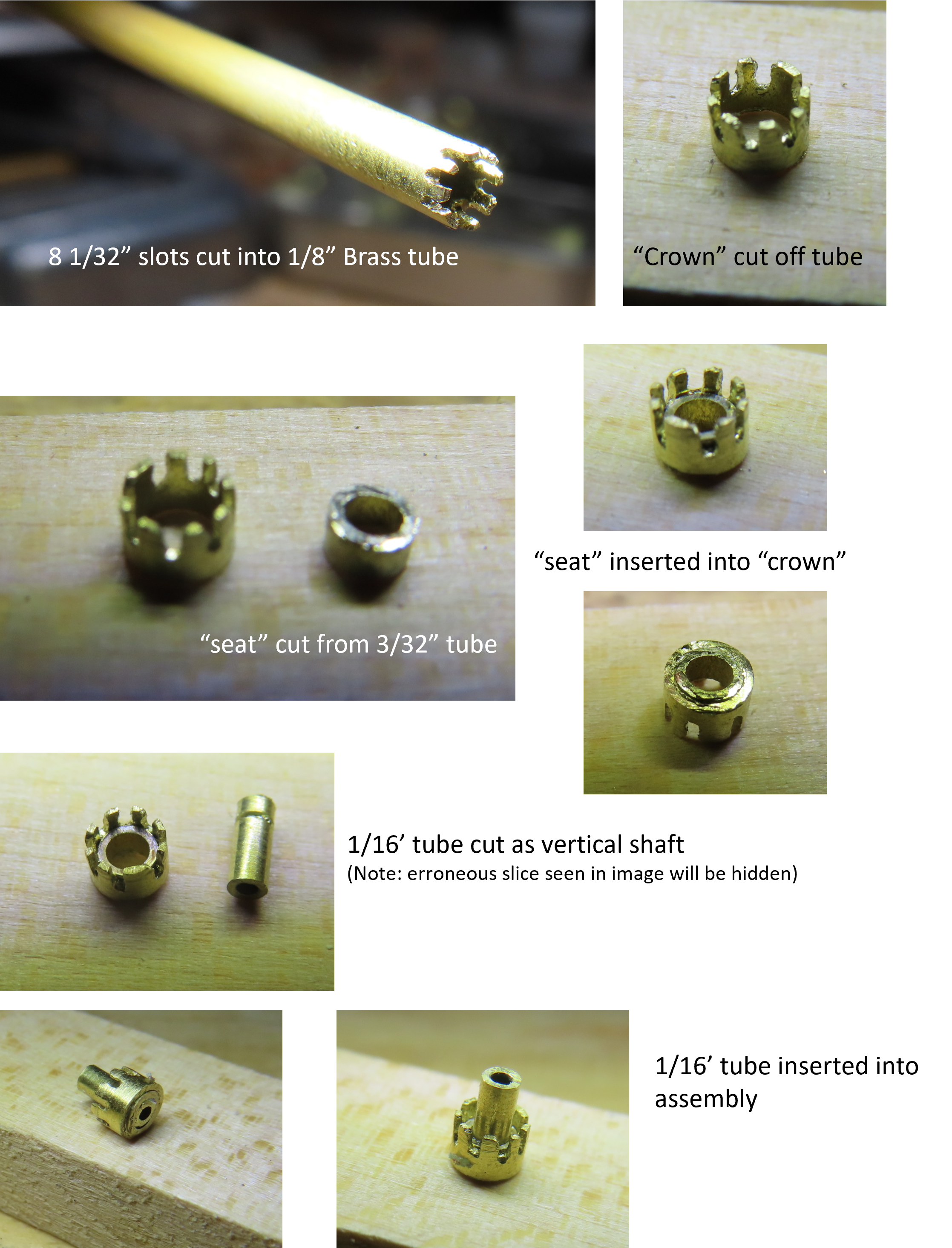
The end of the 1/8” tube was sawed off, producing a 1/8”Ø “crown” shaped component. Next, a slice of 3/32” tube was cut creating the seat ring, which was inserted into the bottom of the “crown.” Inside of that, a length of 1/16” tube was inserted creating the inner wall and axial of the hub assembly. Following the plan, additional pieces were added to create the hub.