HOLIDAY DONATION DRIVE - SUPPORT MSW - DO YOUR PART TO KEEP THIS GREAT FORUM GOING! (Only 13 donations so far - C'mon guys!)
×


JSGerson
-
Posts
2,611 -
Joined
-
Last visited
Content Type
Profiles
Forums
Gallery
Events
Everything posted by JSGerson
-
 Marcus,K.: I took another look at 35208 and you are correct, it is "risers." I stand corrected.🤔
- 233 replies
-
- 2
-

-
- Model Shipways
- constitution
- (and 5 more)
-
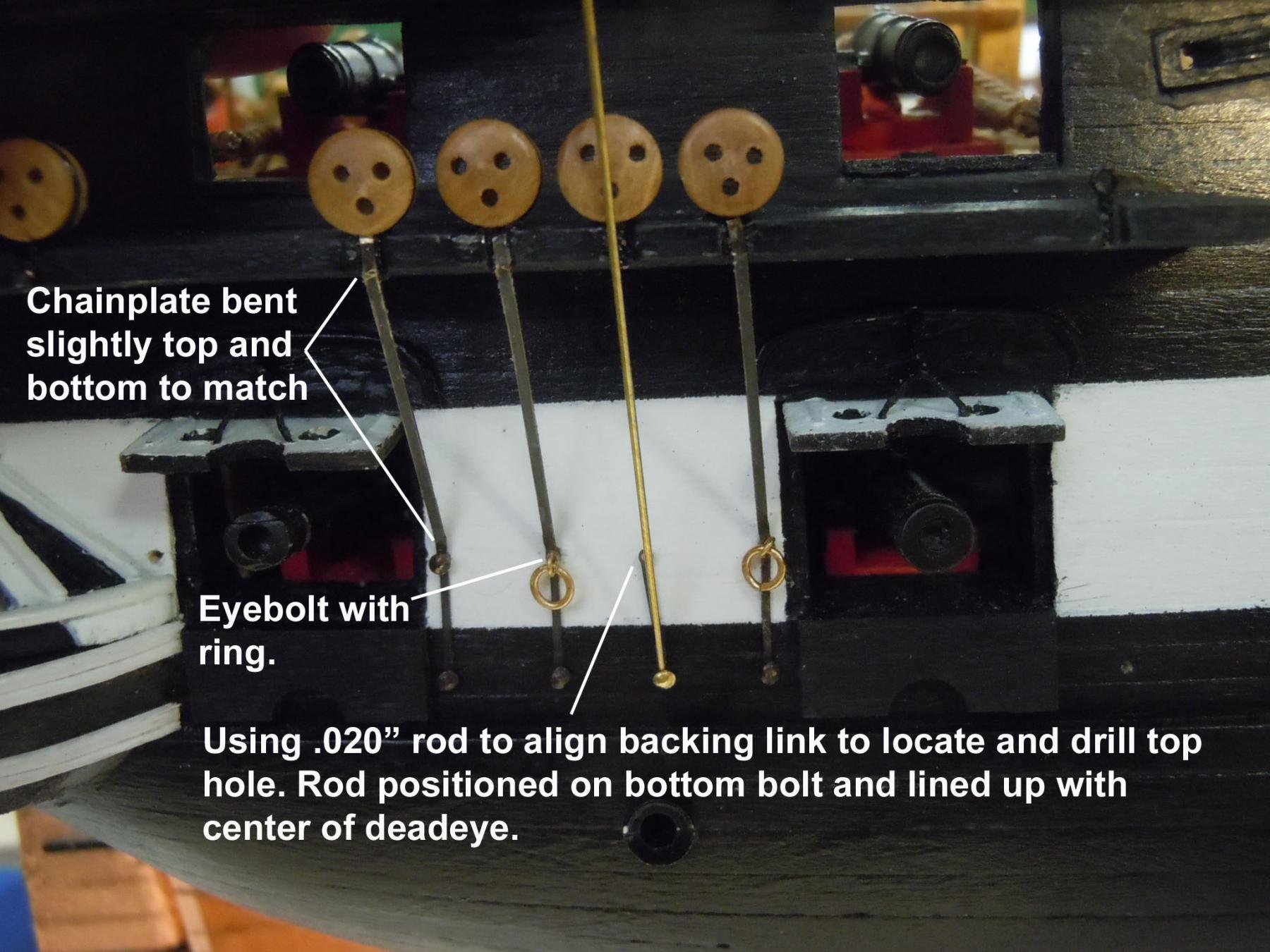
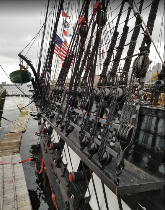
From what I surmised from the images Ken provided, he did not attached the deadeyes to the chain plates. He twisted the wires stropping the deadeyes creating a tail which was then inserted into the channel. The chain plates were laid on top of the tails and extended to the hull. The "joint" was eventually covered over by the channel cap hiding the false connection. A little bit of modeler's sleight of hand.


-
I read it the same way but made some minor corrections (typos, different interpretation of words, & omissions) in red. Note the term "viz." means "in other words" (I had to look that up). This plan has been drawn as a matter of record and comparison with Navy Yard Boston Midship Section Plan No 34526 BU C.S.A No 130241 which has been approved by that bureau subject to checking and revision to bring it in accord with additional data as may come to the attention of the commandant before any work is authorized and or started. Plan A ?? per original specification is not to be strictly followed in reconstruction. Some features will however be incorporated viz.: height of main hatch coamings, diagonal risers chamfering edges of wales and black strakes installation of third strakes etc. Whether this helps or not, 🫤 I don't know.
- 233 replies
-
- 1
-

-
- Model Shipways
- constitution
- (and 5 more)
-
USS Constitution by mtbediz - 1:76
JSGerson replied to mtbediz's topic in - Build logs for subjects built 1751 - 1800
Always glad to be of help Jon -
USS Constitution by mtbediz - 1:76
JSGerson replied to mtbediz's topic in - Build logs for subjects built 1751 - 1800
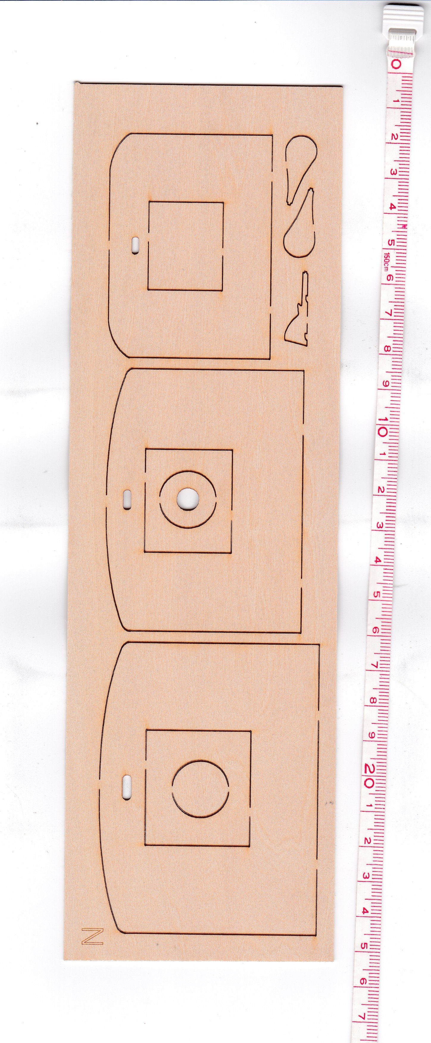
I'm surprised that the MS plans don't provide plans for these parts. I copied what was provided in the kit with a centimeter scale for your convenience. Jon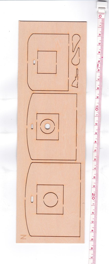
-
USS Constitution by mtbediz - 1:76
JSGerson replied to mtbediz's topic in - Build logs for subjects built 1751 - 1800
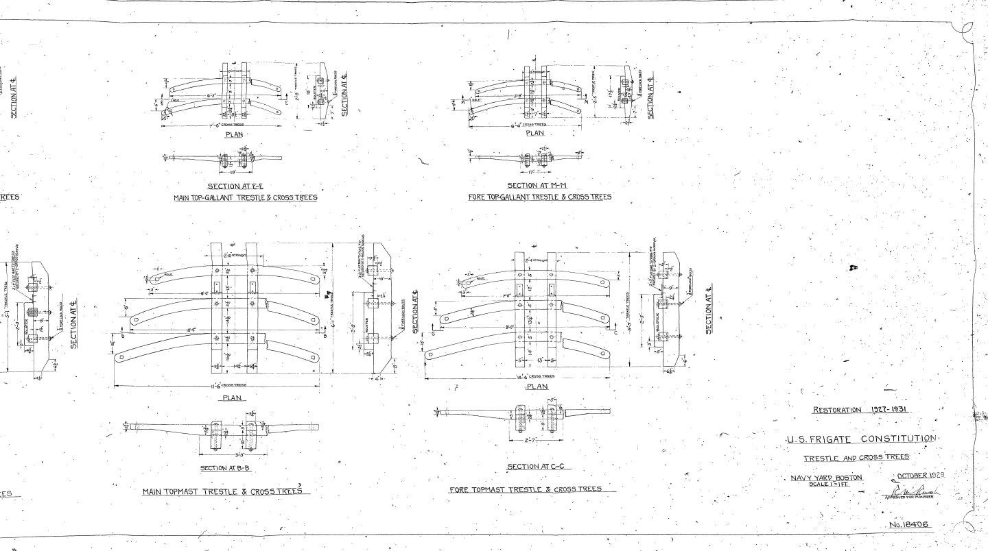
US Navy Plans attached Jon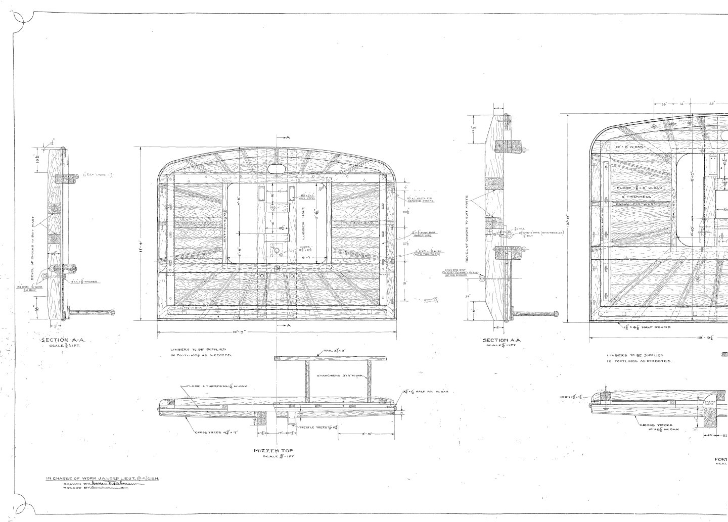


-
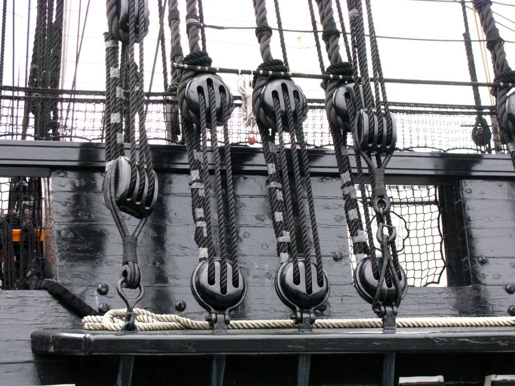
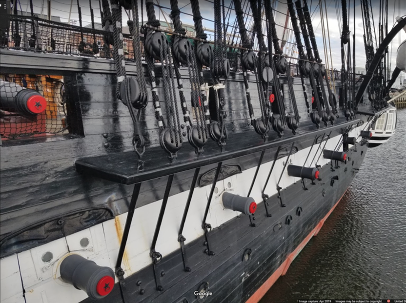
I sent these images to Mustafa as well. It shows what the actual connections look like to help guide you. In my opinion, your idea should work better if you use the stronger boxwood for the channels instead of basswood. Jon


-
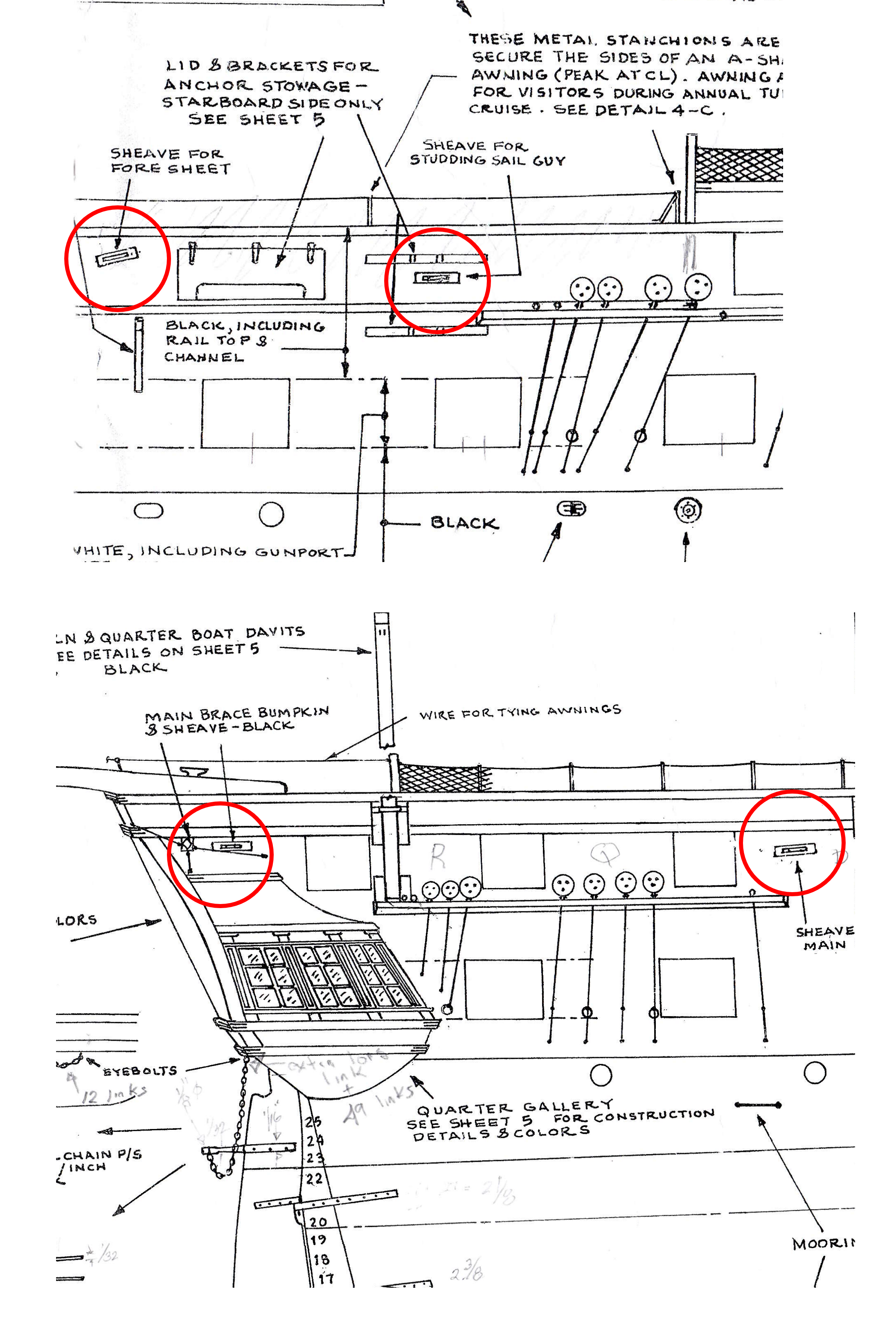
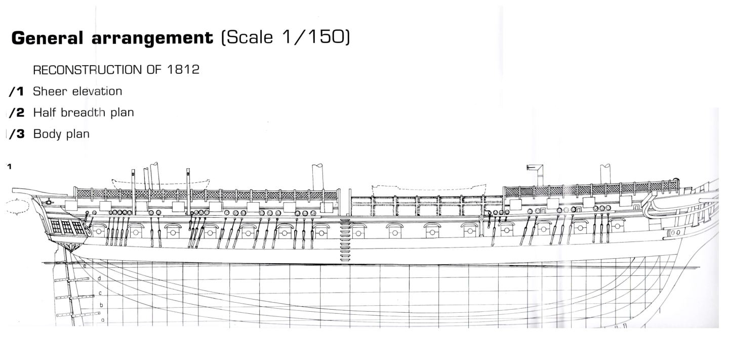
The MS plans are based on the 1927-31 renovation with some more recent details scattered about. What makes this renovation unique is that it added the top gallant rail, which has since been removed in more recent renovations. I checked Marguardt's AOS book on the USS Constitution and the 1812 configuration. Surprisingly, it showed no sheaves. Sheaves did appear in later configurations of the hull that he presented. As an aside, I can't believe/understand why sheaves would be on the gun deck. You're in the midst of battle, the command is to move the sails. You are going to have run down a ladder to another deck to pull on ropes and get your subsequent commands relayed to you through one or more people with the noise of a battle in a confined space? Doesn't make sense to me. To be sure, I would DM MrBlueJacket for clarification/explanation. He will respond to you. Jon
-
I feel like I have built up an unwarranted reputation. Yes, I have amassed a wealth of pictures and plans, but I am no expert. When it comes to interpreting historical designs, I am a babe in the woods. I wish I could help, but the USS Constitution is an enigma and full of contradictions. I have yet to see a full set of plans for just one era. What I have reminds me of that old Johnny Cash song about building a car one piece at a time with parts from different years. That what I have, plans from different eras but not one complete set. Sorry I'm not more helpful Jon
- 233 replies
-
- 2
-
-
- Model Shipways
- constitution
- (and 5 more)
-
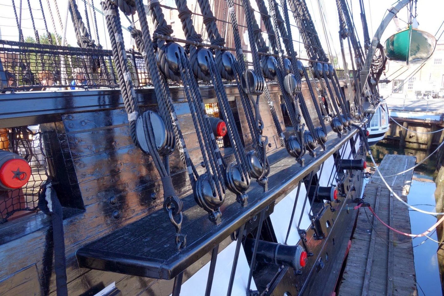
I got curious by your statement, "Both sheaves are at gun deck level..." According to Model Shipway's plans (see attached) , there are 4 (1927 version) sheaves per side in the spar deck bulwarks, not the gun deck. I believe you misspoked. The question as whether to include them or not to me at least, is a question of scale. At 1:96 they will disappear as they are black on black and very small. If it is a question of accuracy, yes I would put them in, just by drilling a couple of holes and a groove between them to simulate the sheaves. The sheaves are there whether or not the ship is rigged for sails; it's part of the hull. The same argument could be made about the bow and stern boomkins. They are used only for the sail rigging. My model won't have sails, but I have added boomkins to the bow so far in my build. This is only my opinion, I like detail. It is what separates one model from another. I hope this helps Jon

-
Now that you point it out, I checked my pictures of the actual ship and those caps are made of copper. I hadn't paid much attention since I'm not working on fabricating those yet. I can buy a Uxcell 1Pack Copper Flat Bar, 5/32" T x 3/8" W x 10" L Copper Bar from Walmart. Hopefully, I should be able to slice that up that softer metal easier than the brass. Jon
-
I painted the small connector blocks on the brass railings which are barely visible. The caps are larger, more prominent, so yeah, I would like to use brass. We'll see when the time comes. As for buying major modeling equipment, I don't think so. I figure I've got a couple more years on the Conny and most of the woodwork is done save for the masts and yards. I turn 79 this November, so I will be in my 80's by the time I'm finished with her. I'll probably start thinking about reducing the stuff I accumulated over the years. Jon
-
Your fife rails look great. I don't have a milling machine so I'll have to work out another method to fabricate the brass caps. Off the top of my head, I suppose I could buy a 5/32" (I think that's the proper dimension) square brass bar and slice off 1/32" pieces, like cutting a loaf of bread, to make my caps. Worst case, I could just paint the wood tops brass color. Time will tell. Jon
-
USS Constitution by mtbediz - 1:76
JSGerson replied to mtbediz's topic in - Build logs for subjects built 1751 - 1800
I always like to share the photos I've collected over the years. Jon -
USS Constitution by mtbediz - 1:76
JSGerson replied to mtbediz's topic in - Build logs for subjects built 1751 - 1800
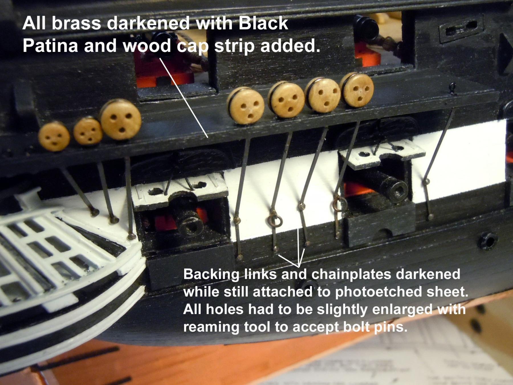
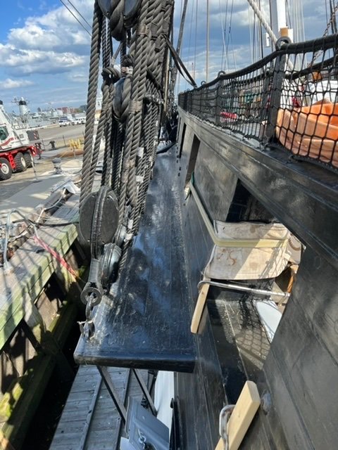
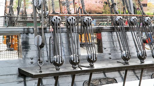
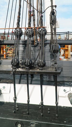
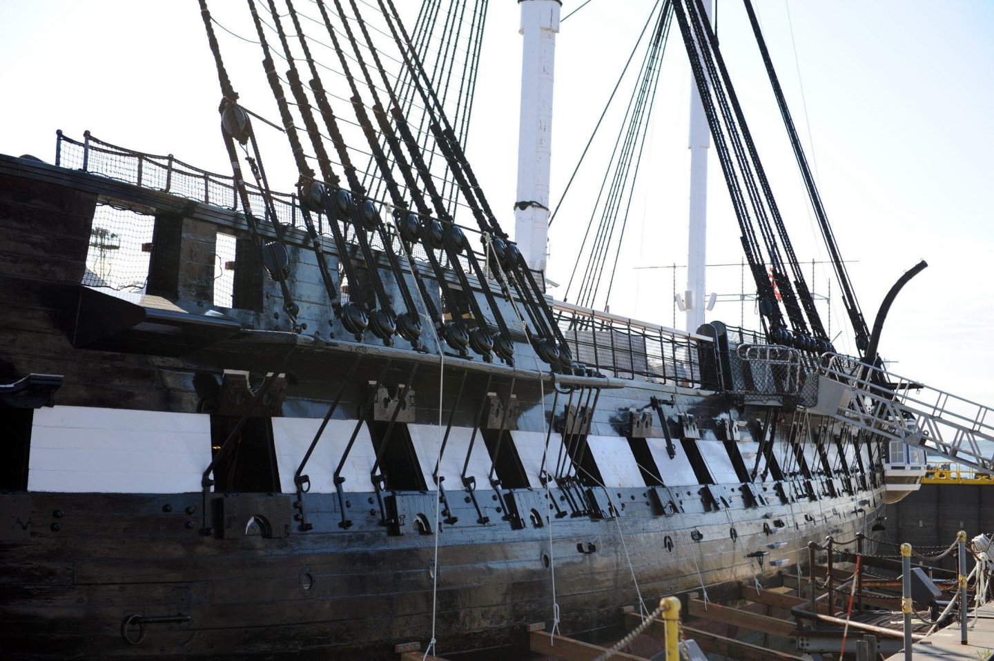
Mustafa, I saw your request for channel images. While we wait for Gregg's photos, here are some of the images I have that may help you. Jon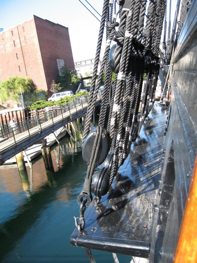

-
USS Constitution by mtbediz - 1:76
JSGerson replied to mtbediz's topic in - Build logs for subjects built 1751 - 1800
One of the hardest areas to photograph is the seat-of-ease location because the public is not allowed to go through the bow access ports. I have just 4 or 5 images with just partial glimpses of the bowsprit and the seats in that area. An ideal shot would be from one of steps on the bowsprit looking aft, downward into the bow. If you can get one of the museum employees or Navy men/women posted on the ship to use your camera to go into that area and photograph anything and everything, from all angles they can, that may help a lot of future model builders. When I was there back in November 2014, I thought of that too late and my available time was running out. And now, since the 2015-17 restoration, the bow topgallant rail has been removed, so there are even less current images available. Enjoy your trip. Jon -
USS Constitution by mtbediz - 1:76
JSGerson replied to mtbediz's topic in - Build logs for subjects built 1751 - 1800
Excellent workmanship. I would expect nothing less from you! Mine should look half as good as your by the time I get that point. Jon -
Beautiful pieces or work! What method did you use to add the brass caps on the posts? Jon
-
That works too Jon
-
Drill a round hole in to vertical bitt no wider than the width of the horizontal post. Cut two pieces of square stock to the length that will exposed horizontally plus an addition length that will fit into the drilled hole. Round off one end of the horizontal post so it fits into the hole. Do the same for the other side. Thus you have a square peg in a round hole and it looks like it passes completely through. Jon
-
You might even get away with painted vertical lines!!?? Jon
-
There is always the layer cake alternative, the method I used for my catheads. Although, I too would prefer just to drill them. Jon
-
I too plan on replacing the fife rails. The ones that come with the kit are fragile...very fragile. Look at them crossed eyes and they will break. Imagine inserting or tying off lines to the belay pins and the rails break after they been installed. Not a pretty sight. Using boxwood, NOT basswood, was the proper wood replacement choice. Don't forget to anchor the rail and bitt assemblies to the deck with pins. There will be some stress placed on them when the rigging is installed. Jon Jon
-
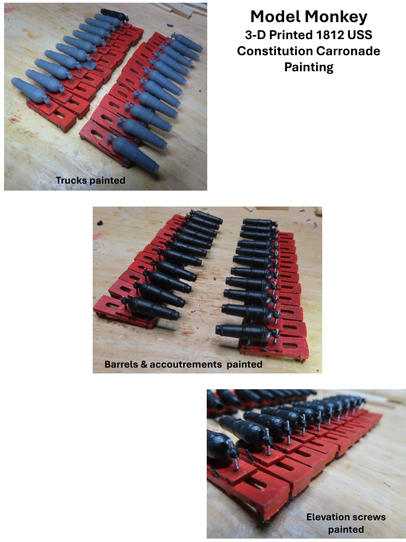
Painting was also a tedious endeavor because I was painting a complete model…22 times. Painting individual parts before assembling is a lot easier. These were complete guns with attached trucks. First, I painted the trucks Model Expo acrylic orange/red. Then I painted the gun barrels, mounts, and small accoutrements on the trucks, Model Expo acrylic black. Getting all the nooks and crannies covered with paint was not simple as I kept missing spots and had to keep going back to cover those surfaces while trying not to touch previous painted areas…but I did. When I fixed those, I reintroduced additional painting errors…etc. Finally, all I had left was the screw mechanism for adjusting the barrel elevation which I painted Testors enamel steel, which I already had.