JSGerson
-
Posts
2,127 -
Joined
-
Last visited
Content Type
Profiles
Forums
Gallery
Events
Everything posted by JSGerson
-
 If you look at Khauptfuehrer's Bluejacket build log, he states: "There is a pitfall concerning the rudder installation. The rudder is made from 5/32" stock. If your kit is like mine, you will have gudgeons and pintles whose interior dimension is 1/8". The folks at Bluejacket swear up and down that the dimension is 5/32" but, trust me, it is 1/8". Bending these to suit is difficult and yields less than satisfactory results. Bluejacket also sells gudgeons and pintles with a 1/4" inner measurement. These are easy to adapt and work well. Drops of glue are used to simulate bolt heads I recommend that you buy 1/4" gudgeons and pintles. They will bend easily to suit, and you will be fine." This might be a solution to your problem. Jon
 -
Have you thought about the color you're going to paint them. Like ER Rich, mine are copper color. His is painted, mine are made of actual copper. If you look at the ship in dry dock (see my log), the gudgeons and pintles are the same color as the rudder underneath them. Some builders have made them all black. the choice is yours. Jon
-
As you know from reading my blog, I'm not the speediest builder, so take this with a handful of salt. I started my planking in April 2020 and didn't finish until July 2021. Of course, my planking was interrupted by working on the the gun deck and its furniture. So cumulatively, it only took about 9 months to plank my hull and prepare it for copper plating. This is not including the planking around the gun ports which was done earlier. So a month or two to plank your hull, that's nothing.😁 Looking good so far! Remember, it's not a race; take your time and enjoy the journey. Jon
-
USS Constitution by mtbediz - 1:76
JSGerson replied to mtbediz's topic in - Build logs for subjects built 1751 - 1800
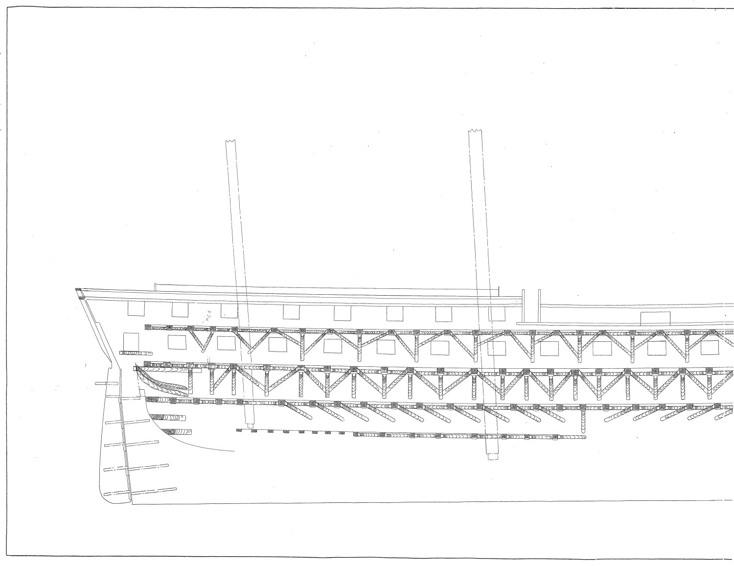
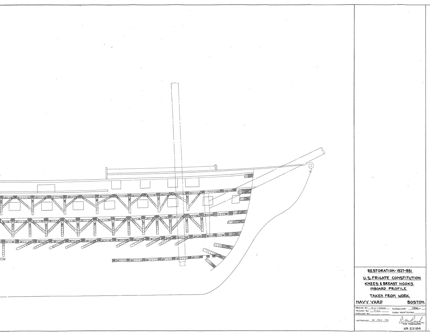
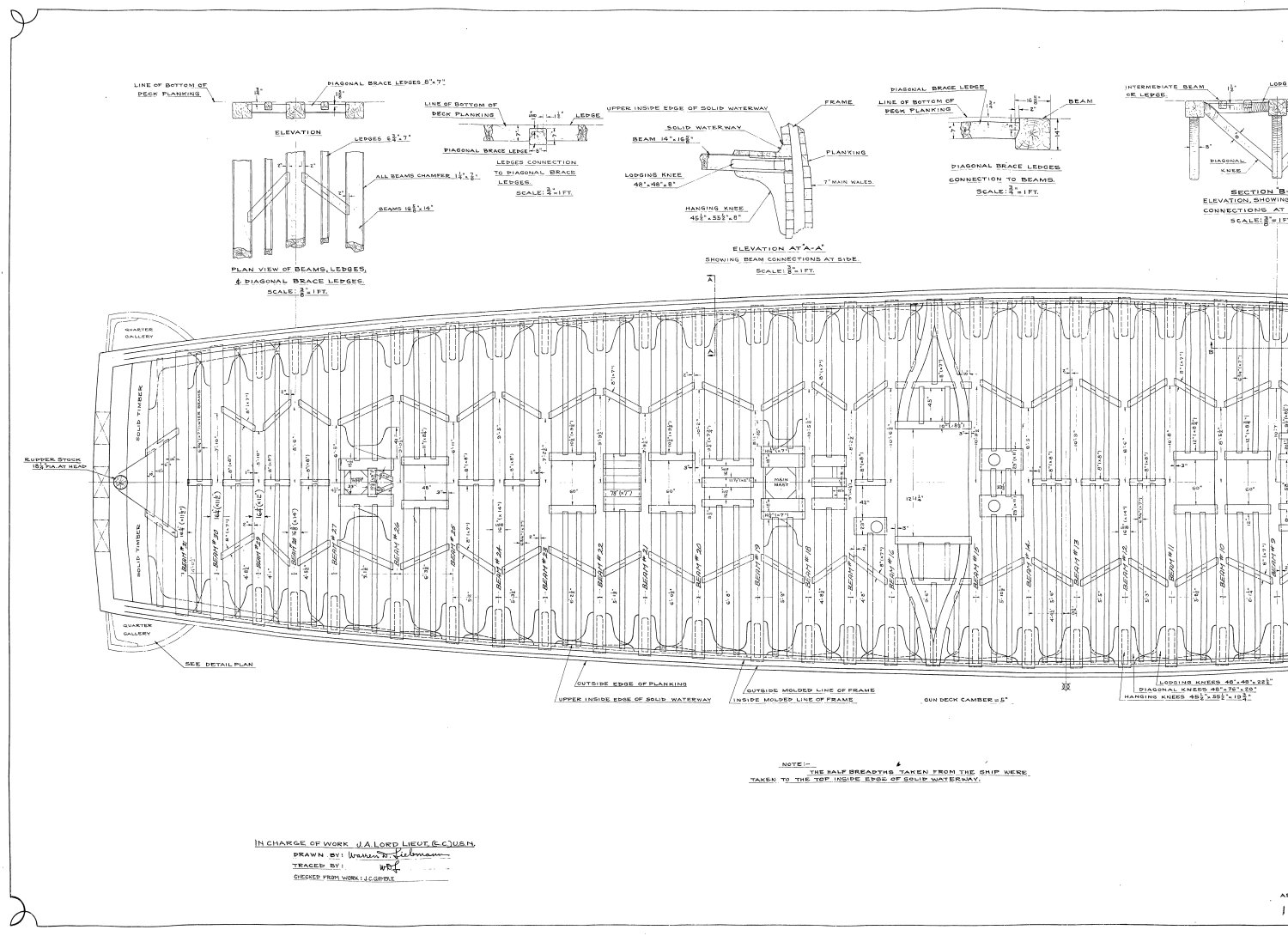
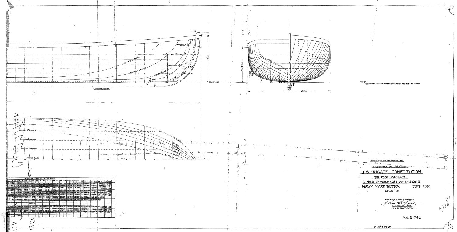
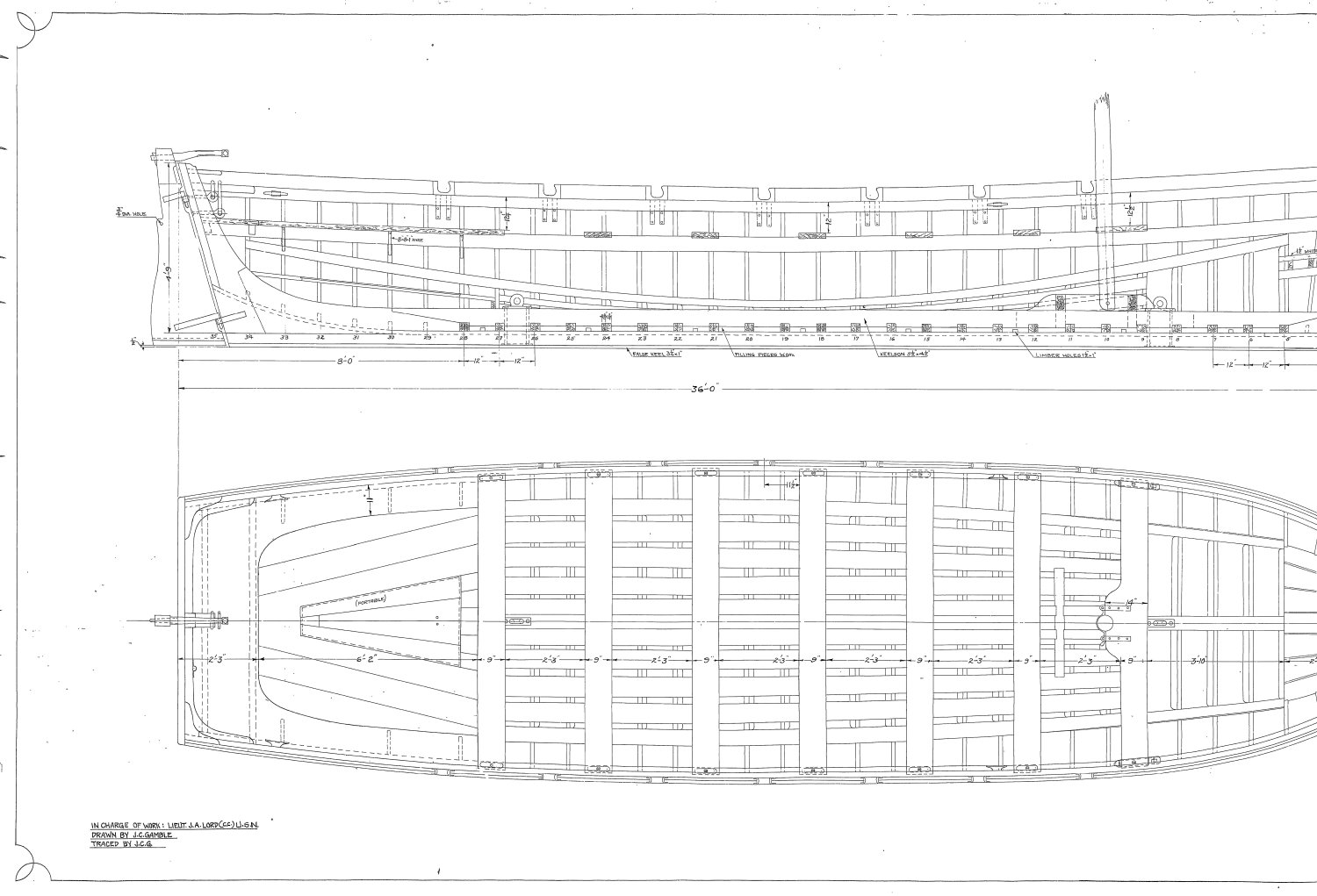
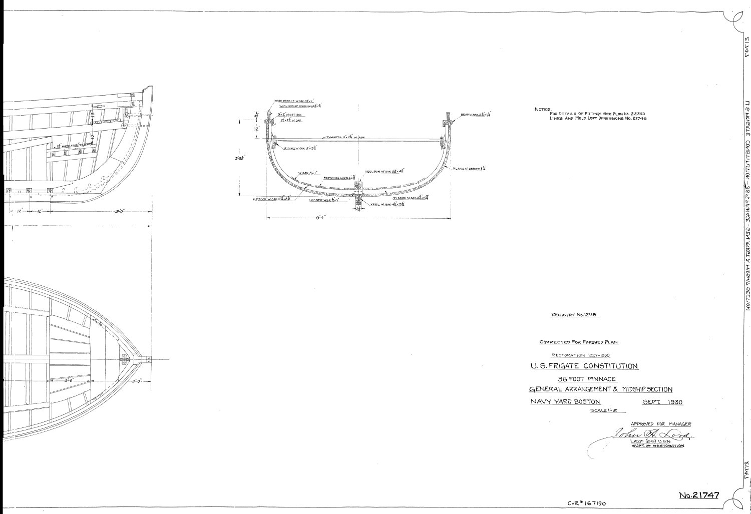
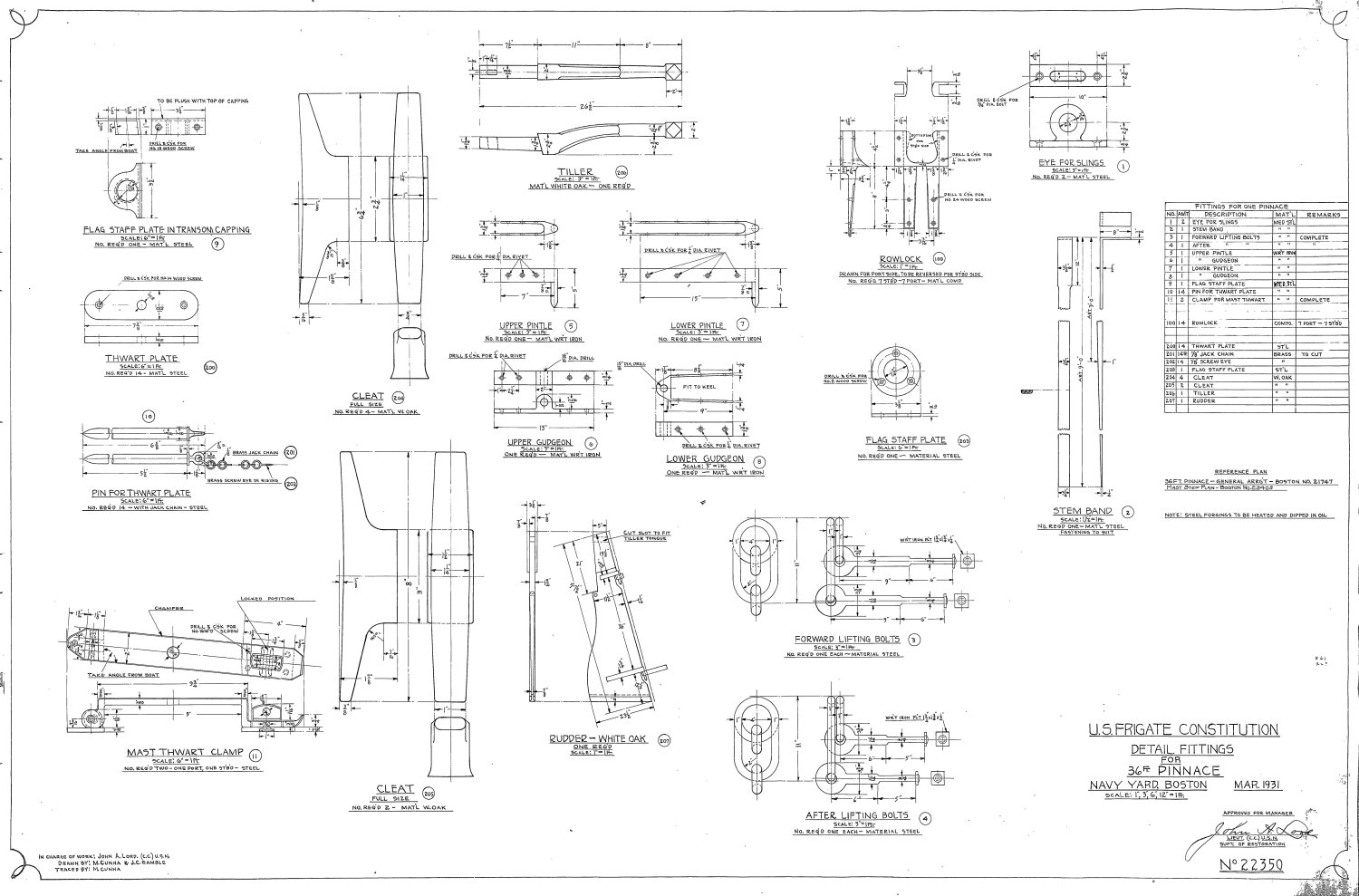
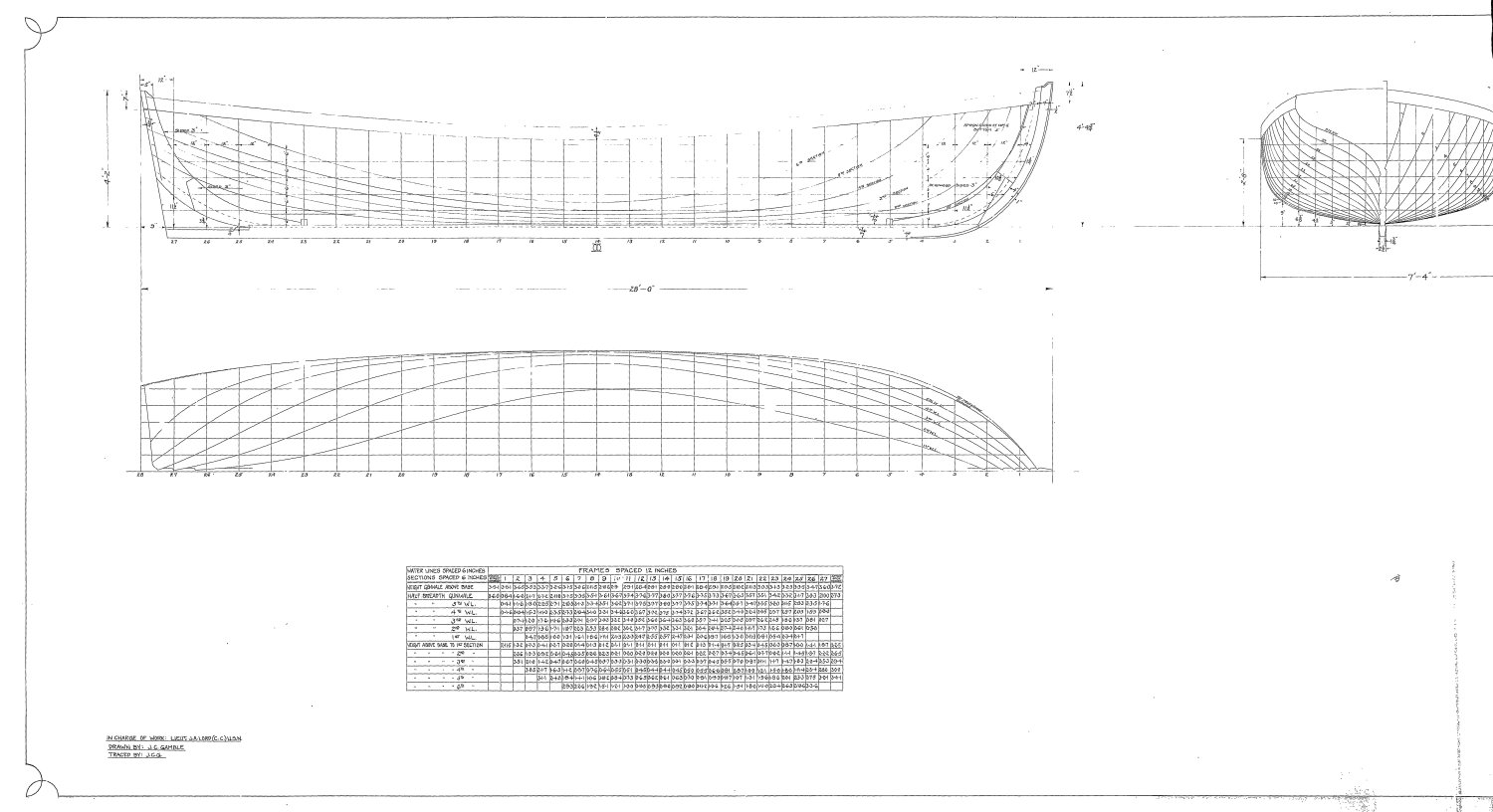
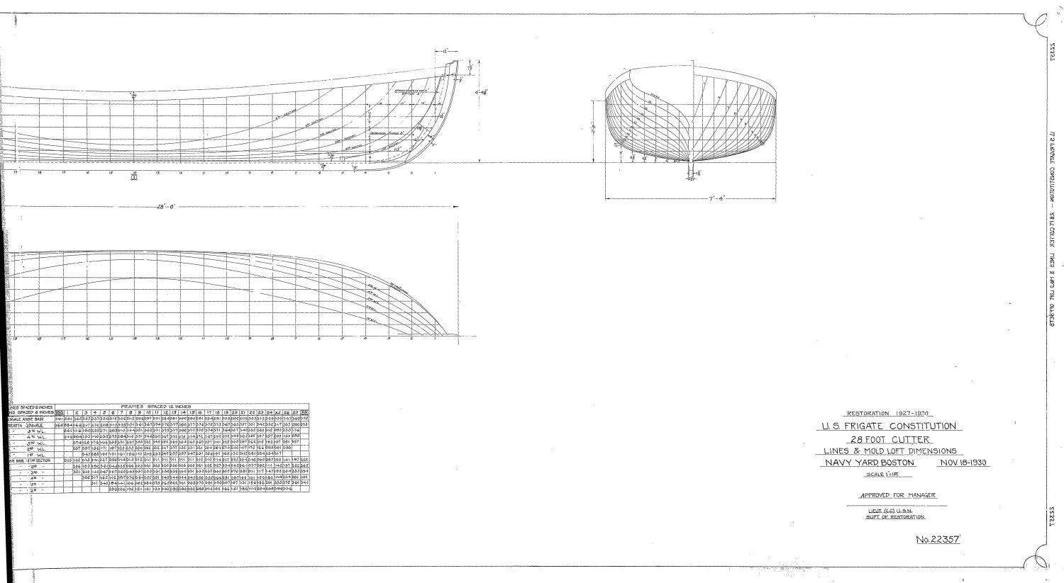
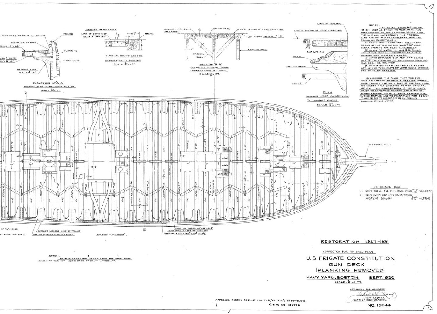
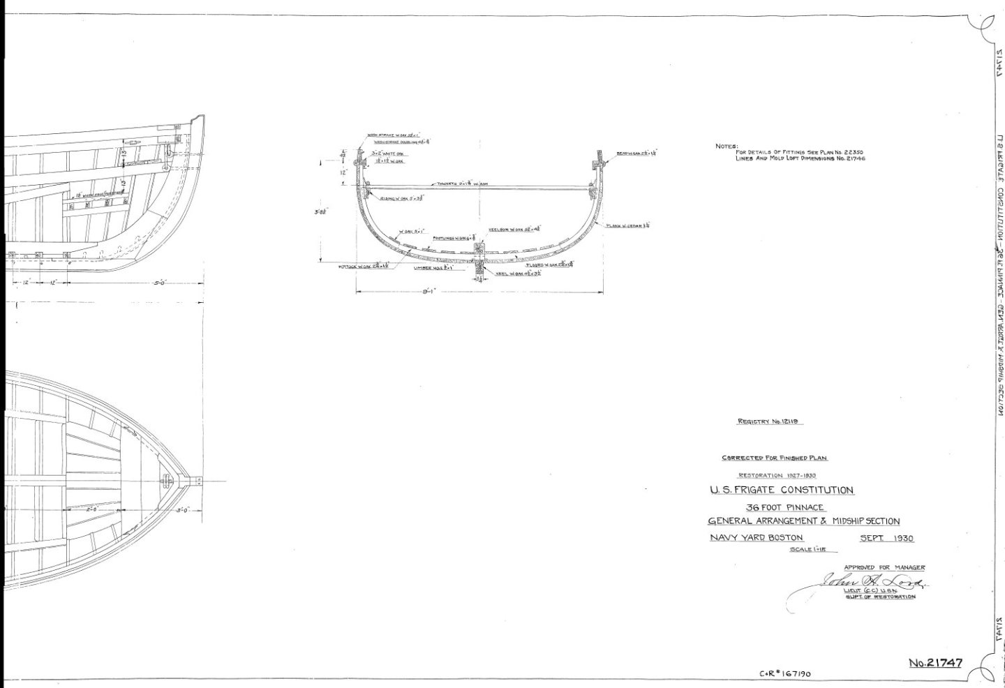
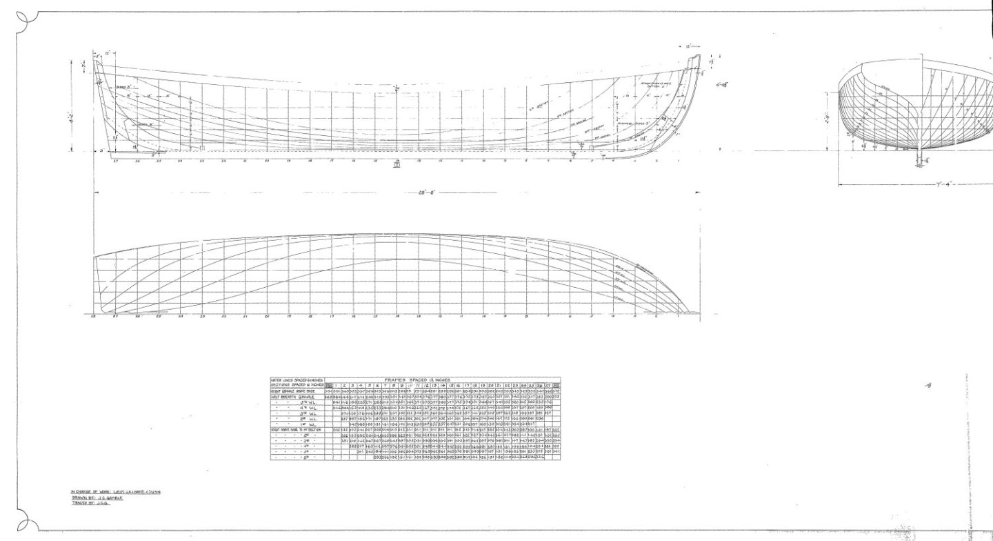
These US Navy plans may help you. Jon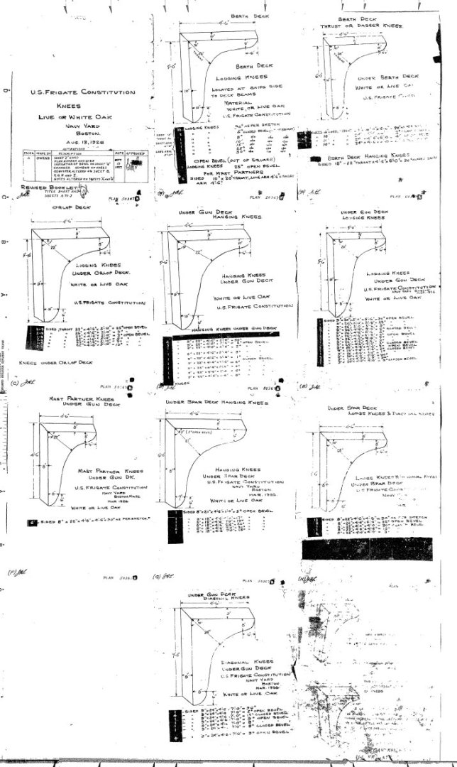


-
It looks like your planking is coming along very nicely. I did a variation of your method of planking. Instead of putting tick marks on the bulkheads, I marking the planks with the bulkhead position, and calculated the proper width the plank should be at that point. Then using a micrometer, shaped the plank ensuring that at each bulkhead mark, the plank was the correct width for each bulkhead position, for each zone. I just couldn't trust my tick marks on the bulkhead. At these scales, the width of a pencil mark can have big consequences. Jon
-
USS Constitution by mtbediz - 1:76
JSGerson replied to mtbediz's topic in - Build logs for subjects built 1751 - 1800
Beautifully done chain stoppers. Too bad nobody but you and God will know they exist on the finished model. We, of course on this build log, get to enjoy them now. Jon -
SUBaron - I had a lot of fun building those boats. Jon
-
I can't tell you how many times I shaped and refined those filler blocks, and shaped and refined, etc., till I thought I was done. I think I didn't I stop until I had planked the hull! Well done BTY. Jon
-
USS Constitution by mtbediz - 1:76
JSGerson replied to mtbediz's topic in - Build logs for subjects built 1751 - 1800
According to US Navy Plan No.: BNS 50976, the larger pump has a 16.25" diameter sphere or 0.212" (5.38mm) at scale and the smaller pump sphere is 14.5 " or 0.188" (4.78mm). As indicated in my log, For both size pumps, I used a 5mm diameter “memory wire end cap” which I still don’t know exactly what their original intended purpose was, from the DIY jewelry section of a crafts store. At this scale you can't tell the difference. Your pumps are looking great. Jon -
USS Constitution by mtbediz - 1:76
JSGerson replied to mtbediz's topic in - Build logs for subjects built 1751 - 1800
Your bilge pumps' rocker arms and frames are much simpler and neater than mine and they give the same viewer effect. Well done! -
I've been collecting the US Navy plans ever since I decided to build the Conny back in 2014 or so.. Why these particular plans are not available from the Museum makes no sense. When the US Navy plans were first added to their website, I know these were there. I checked every plan they offered against what I purchased on their second version CD. The first version CD I got from a fellow builder, had a different file format and others plans that are not relevant to the historic ship (fire prevention, electrical, etc.) as well as the main bulk of what available to the public today. I've also found some plans in the National Archives. I know there must be a bunch more plans in the hands of the many subcontractors who have work on the ship over the decades, but why those aren't available, I don't know. Jon
-
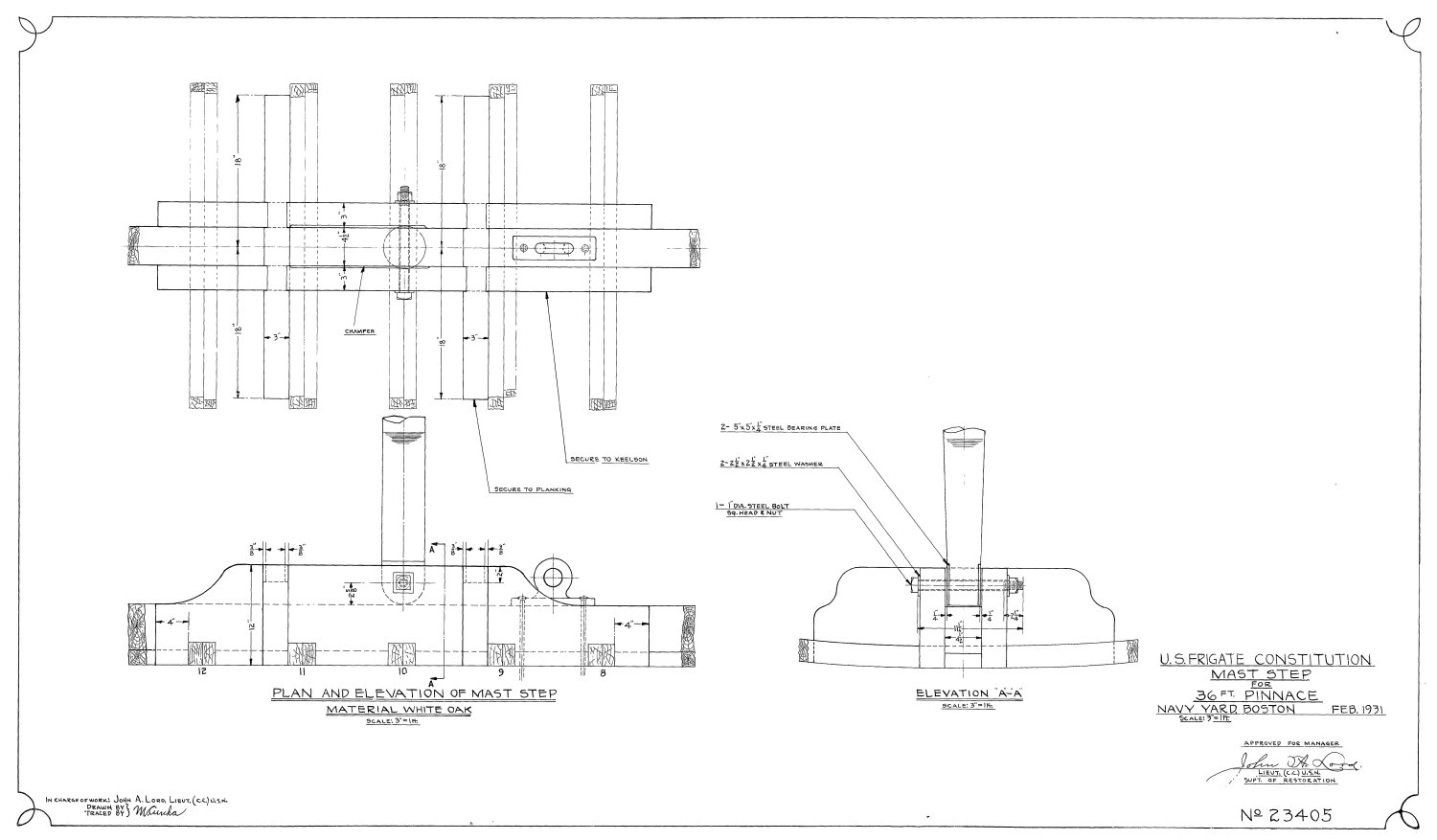
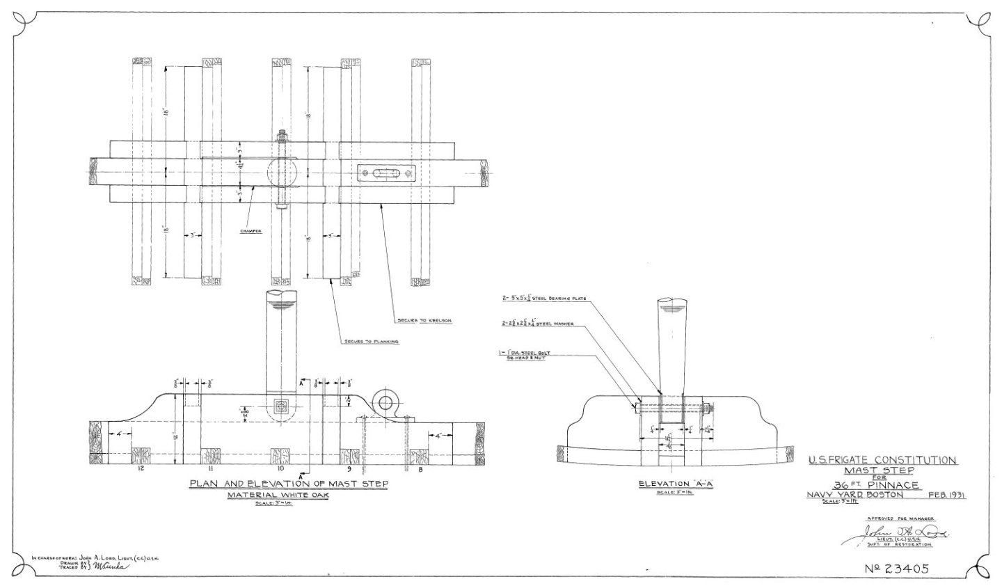
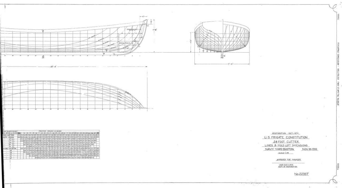
And one more correction, 22357 is the 28 footer. The plan number should be 23405 attach to this post
-
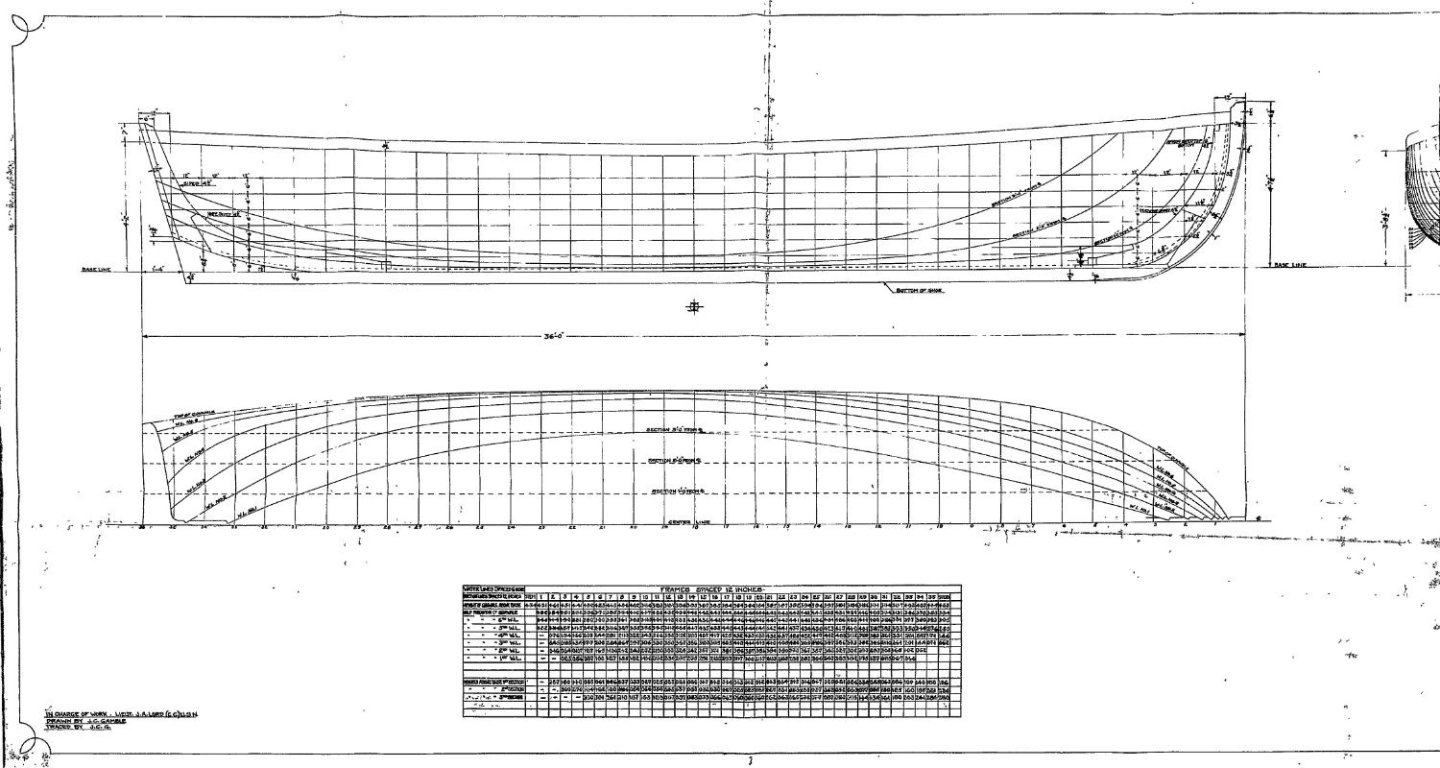
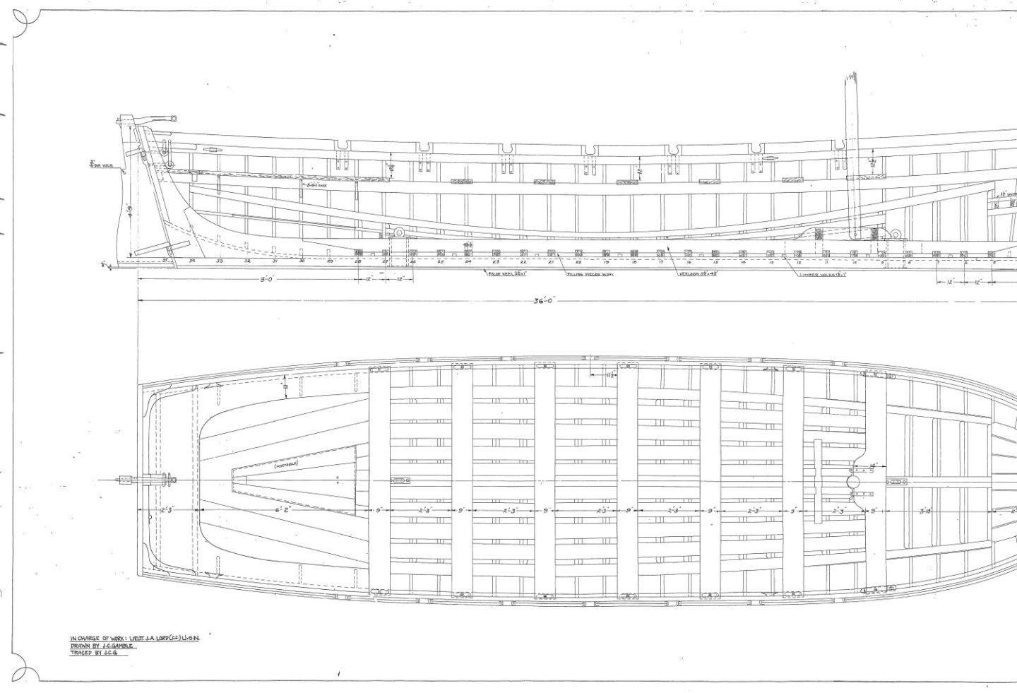
Unegawahya, finding the USS Constitution plans is an effort on the Museum's site, because it's not obvious; why, I don't know. So here is the link: https://ussconstitutionmuseum.org/discover-learn/modeler-resources/ For the 36' Pinnace you need plans: 21746, 21747, 22350, 22357 edit: I just made a liar out of myself, when I checked the museum's site, they don't have these plans. So, I've attached them to this post. The location of the plans has moved over the years. I originally I down loaded them for free from a US Navy site, now gone. Then the museum sold them on a CD (at least 2 versions that I know about) and finally provided the free download on the link above. If there is any US Navy plan I referenced in my build log that you can't find, let me know, because the plans available to the public has also varied on the years. Jon


-
USS Constitution by mtbediz - 1:76
JSGerson replied to mtbediz's topic in - Build logs for subjects built 1751 - 1800
At the time I fabricated my gun deck capstan, I made the square holes with my Byrnes Saw because it never occurred to me to use my Dremel drill on my Dremel drill press to make the cuts. I don't have a dedicated drill press. You just proved there is always more ways to do the same job with equal results. You do what ever is more comfortable for you. As always, nice job. Jon -
In the practicum section 1.4.1, 3rd paragraph Mr. Hunt states: "After cutting the block to length, You will need to reduce it’s thickness to 11/32”." In your first two images of post #12, you drew a line on the counter then it appears your carved down to that line. Were you not reducing the block's thickness? I failed to do that by oversight so I ran into a problem on the gun deck. Jon Oops, I just realized I was responding to a SU Baron comment and not to you Peter.
-
USS Constitution by mtbediz - 1:76
JSGerson replied to mtbediz's topic in - Build logs for subjects built 1751 - 1800
As always, beautiful, neat, and clean workmanship. Wonderful stuff. Jon -
I don't know why you had a problem with drilling the hole in the counter, your set up looks solid. You correctly drilled the hole before carving the counter's final shape. Also I noticed you did NOT make the same mistake I made which was not reducing the counter's thickness by 11/32". So you did good. Just be aware that just about everyone has had some sort of problems with the transom so don't be surprised if you join that club. Mr. Hunt's practicum is a great guide for the novice and intermediate modeler, but his words are not gospel. I always check what other's have done in addition to Mr. Hunt's instructions. And, where I deviated from his lead, my build log usually indicates why. My build is a kit bash. I have added the gun deck interior and based my model primarily on the 2015-17 restoration. The kit (and therefore Mr. Hunt's practicum) is based on the 1927 restoration. so there are visual differences, specifically the removal of the top gallant rail and the addition the the open waist as seen today. As a result, I use the practicum as a guide and bounce around the chapters as I need them and supplement them with the plethora of build logs available for reference. This kit is chock full of sub-models, so enjoy and take your time. Jon
-
USS Constitution by mtbediz - 1:76
JSGerson replied to mtbediz's topic in - Build logs for subjects built 1751 - 1800
You call that slow? You're not slow. I'M slow. You started after me and you're almost surpassing me! I've working on this model since 2017, now that's SLOW!😁😅🤣 -
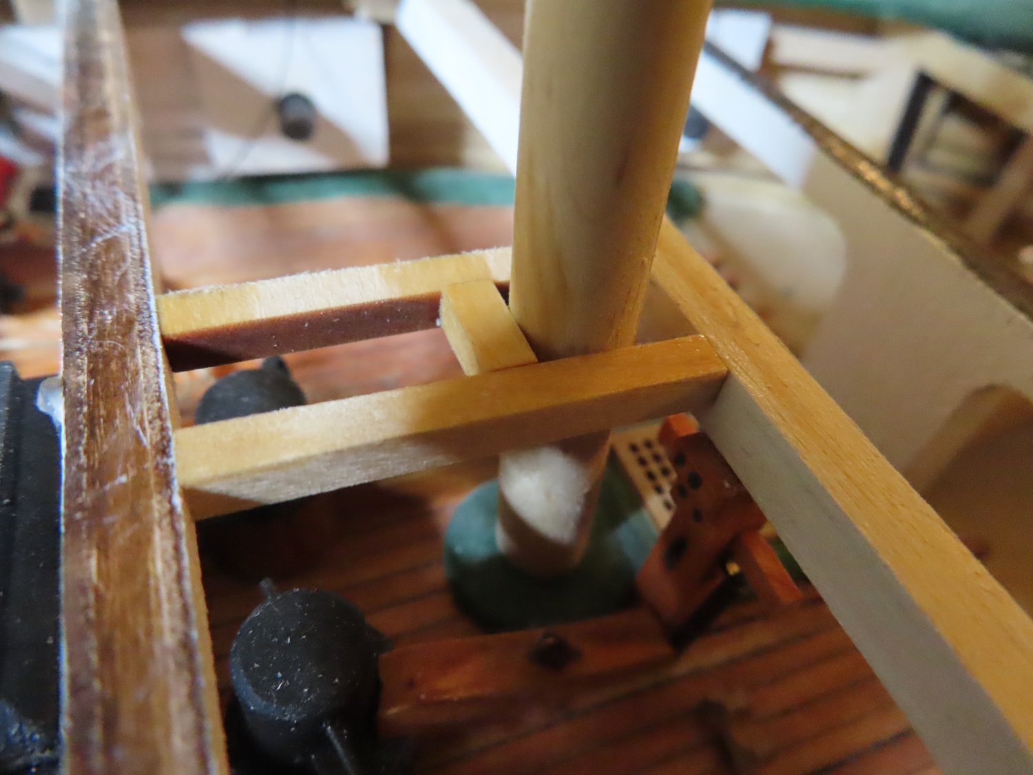
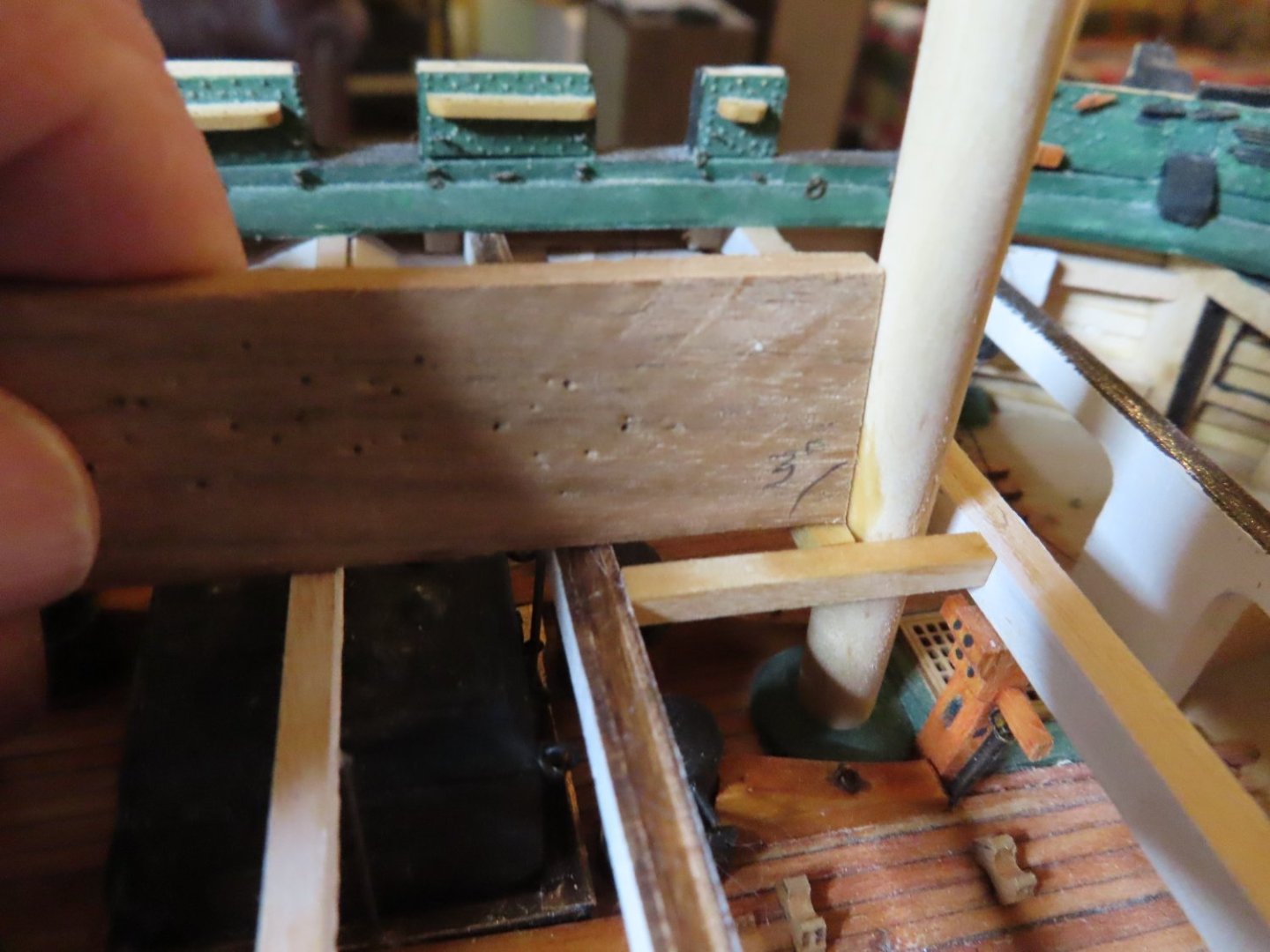
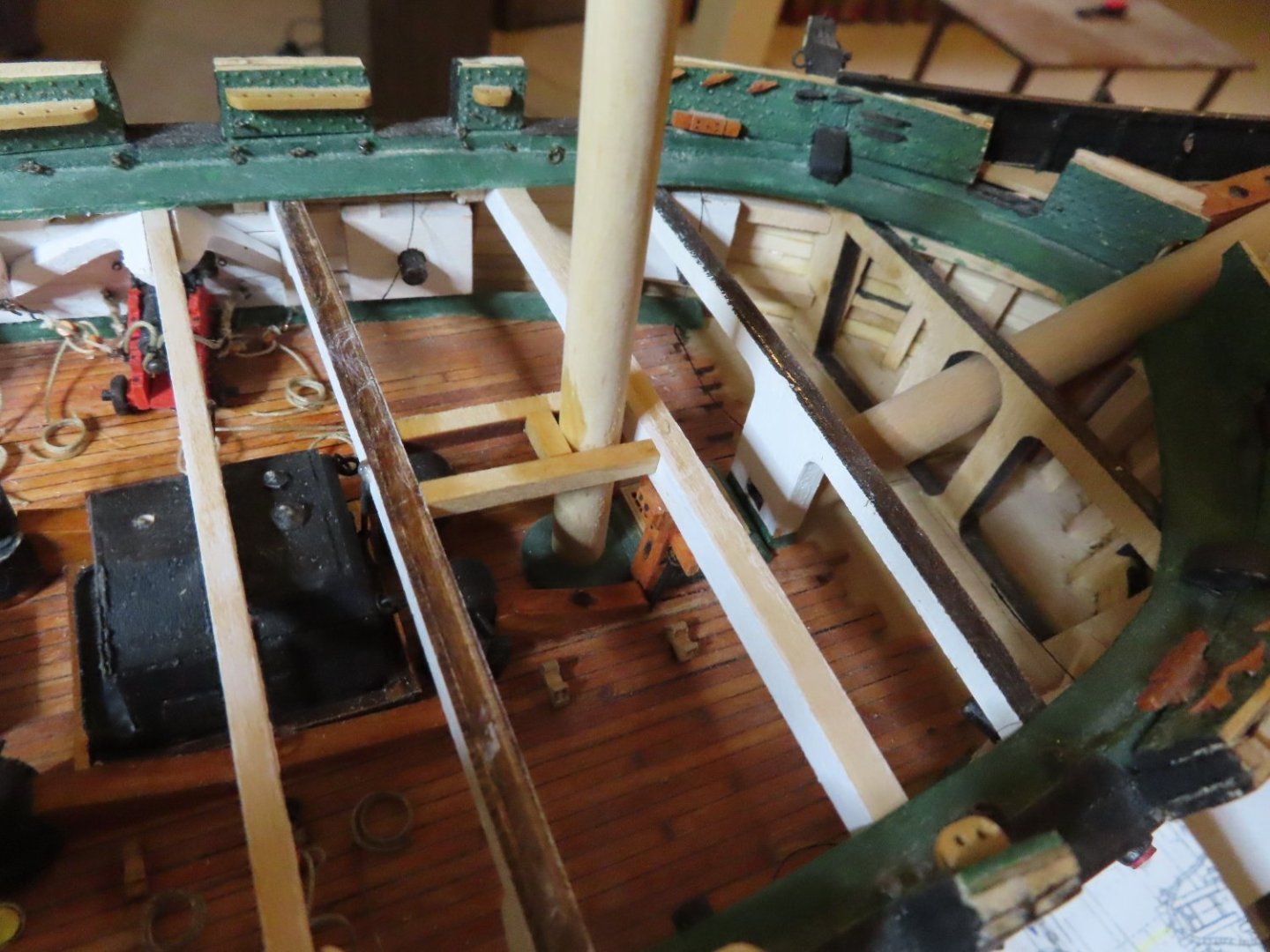
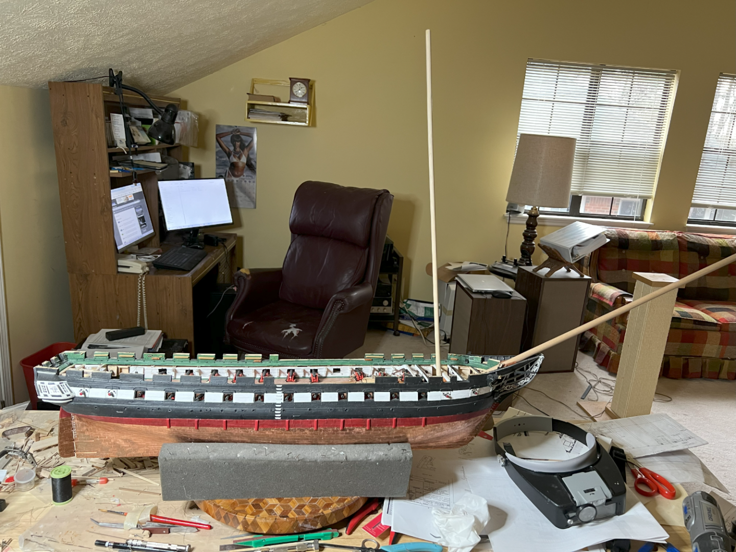
To fabricate the fore mast opening in the spar deck, two structural members were installed between bulkhead Beams C and D offset equally from the centerline by the width of the fore mast dowel. The dowel, sitting in its seat on the gun deck. restrained in its side to side motion, was now perfectly vertical to the beam of the model. Next, a piece of scrap wood’s edge was cut to 3° from the vertical. The scrap wood was now a 3° mast gauge. Placed on the beams, the dowel was pivoted aft back against the gauge and a cross beam glued into place to restrain the dowel’s aft movement. The dowel still has a little forward movement to facilitate removal and then its final placement. Once the foremast is seated again and leaned against the cross beam, it will at the proper rake of 3°. It is to be noted, that the position of the foremast on my model, is not exactly in the same position as shown on the MS plans. The MS plans have the fore mast seated in the C-bulkhead just under the spar deck planking. My fore mast is completely behind the bulkhead C and obviously seated in the gun deck’s extended keel. Why the slight aft position shift, I don’t know. And just for grins and giggles I took a photo with the bowsprit and foremast dowels to get a sense of size of the model. That sucker is biiiigggg!

-
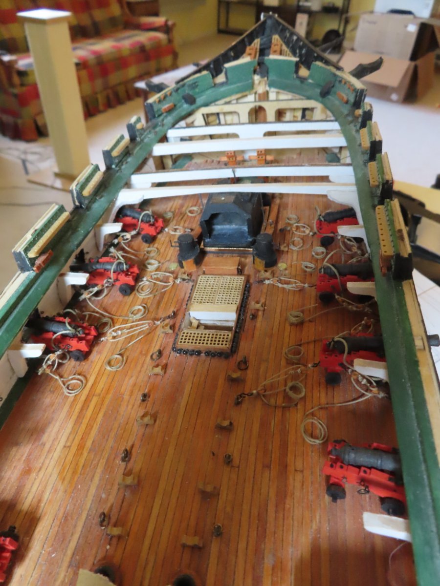
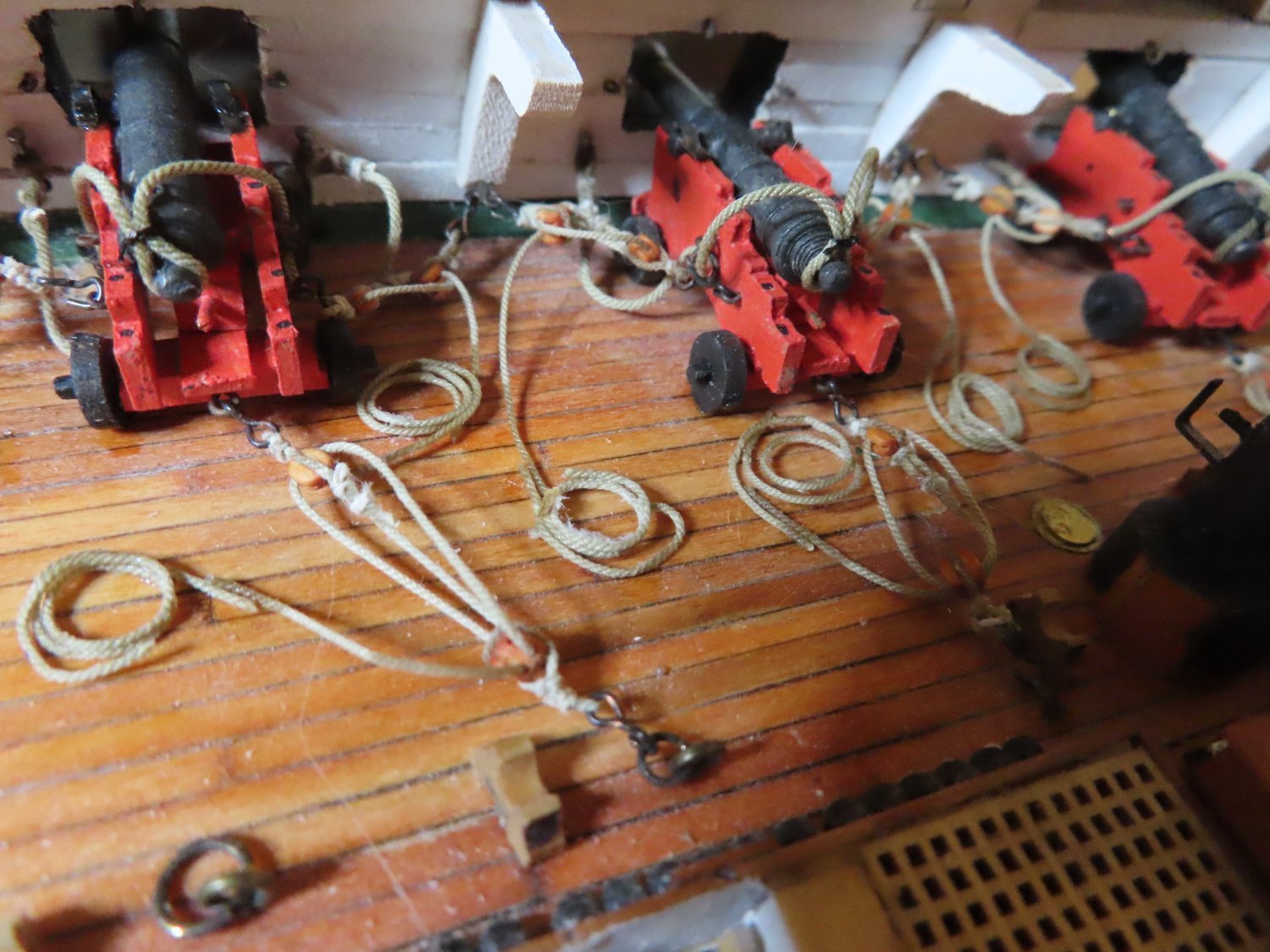
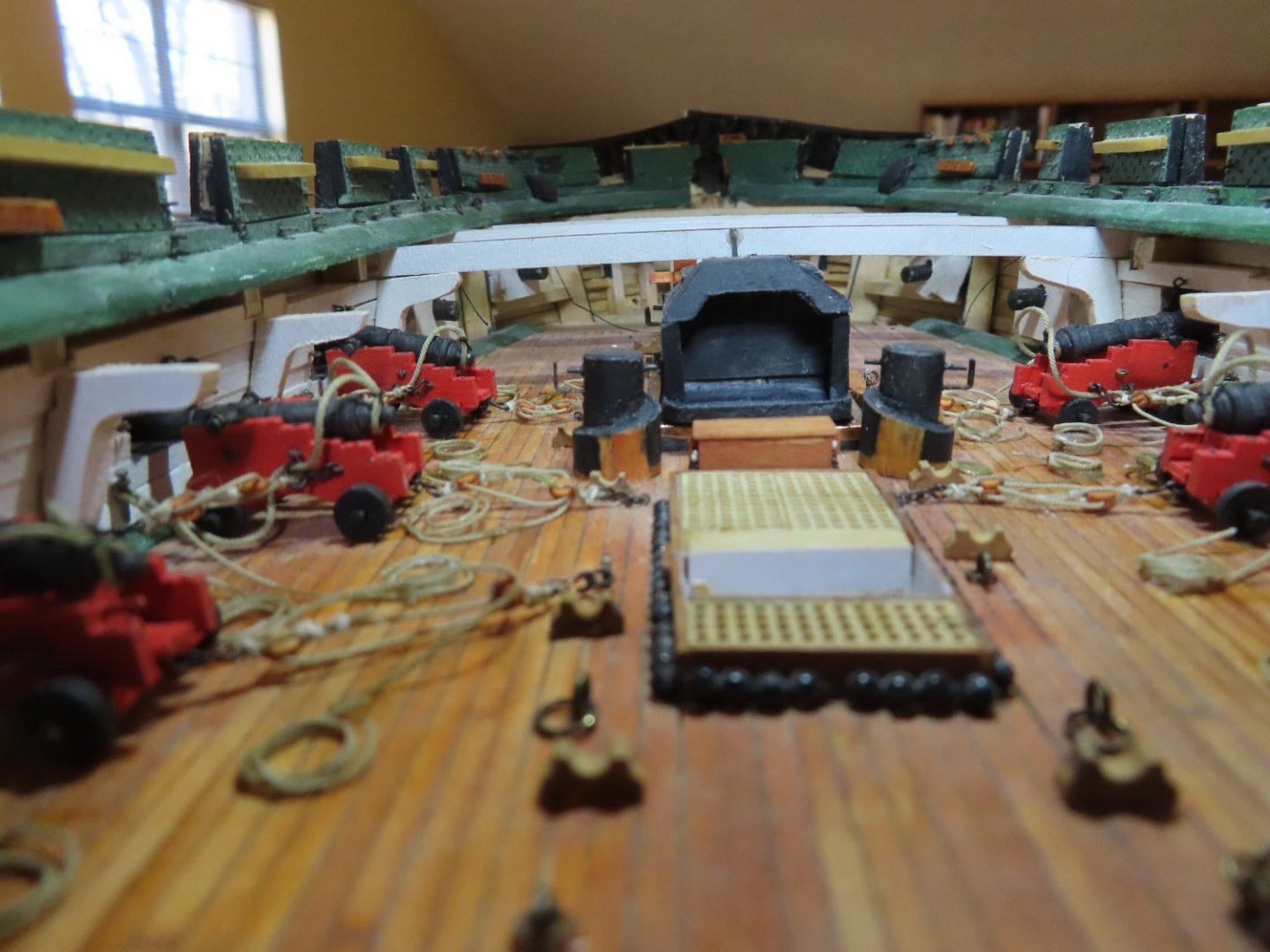
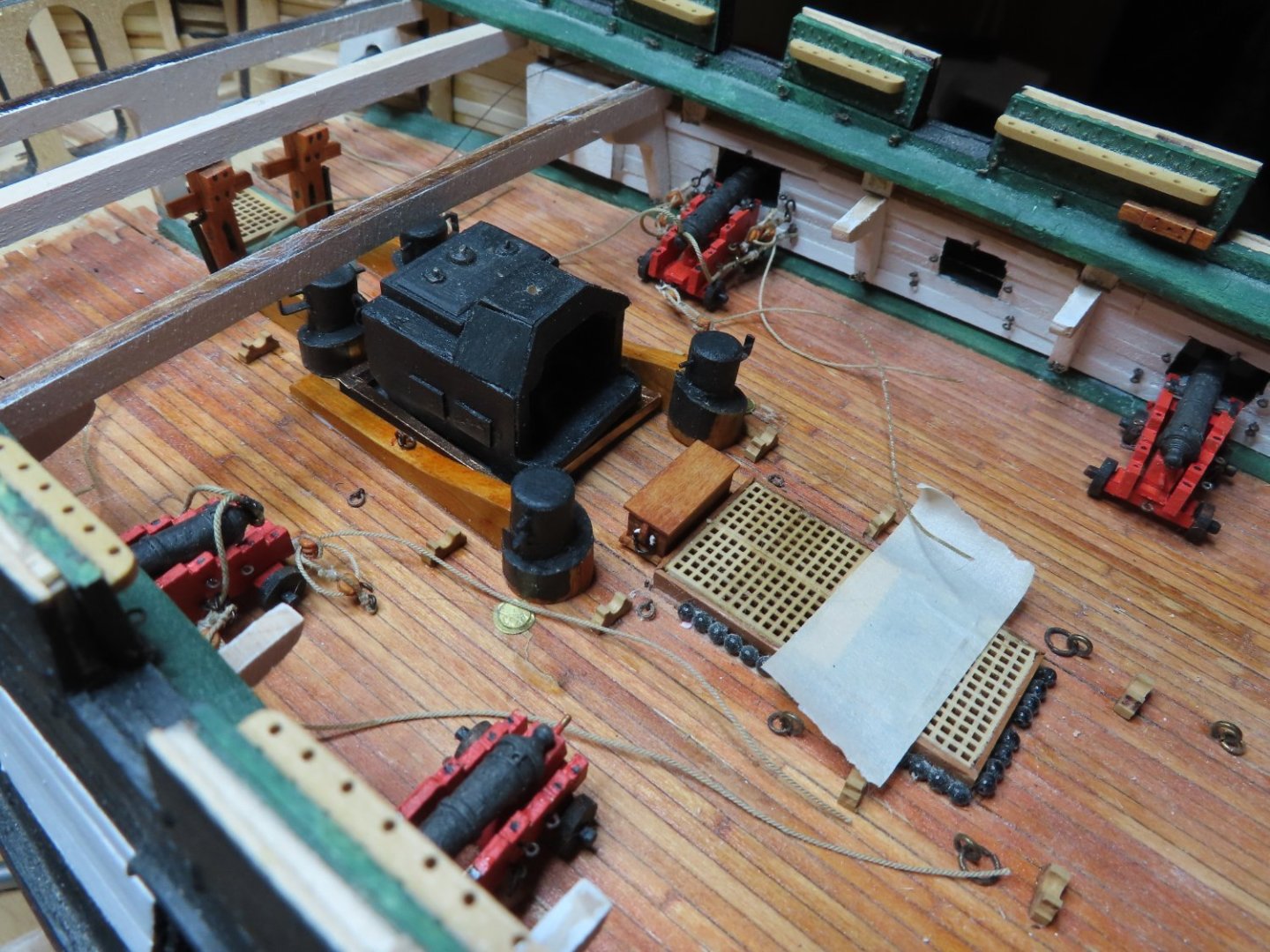
I am not a sailor. I have zero experience on a large sailing ship, especially on a vintage one. Obviously, I have boarded the USS Constitution and all the lines were neatly tucked away for the safety of the public. The only working commissioned naval vessel I have been on believe it or not was a Soviet destroyer on a good will tour in the mid 1970's in Boston Harbor. You didn't see too much, but that ship was as neat as a pin because it was on public display. In pictures of vintage sailing fishing vessels I've seen, there were rope lines all over the place. I assume once the boat was returning to port with its load of fish, they made everything "ship shape." The guns on my model are at the ready, in firing positions so I can't imagine the crew taking the effort to make things visually neat like spiraling rope coils, but probably workable neat. That's why the ropes are simply coiled and in position to be used for firing and reloading the guns. This set up is my best guess and you may be totally correct and I'm totally wrong. Jon
-
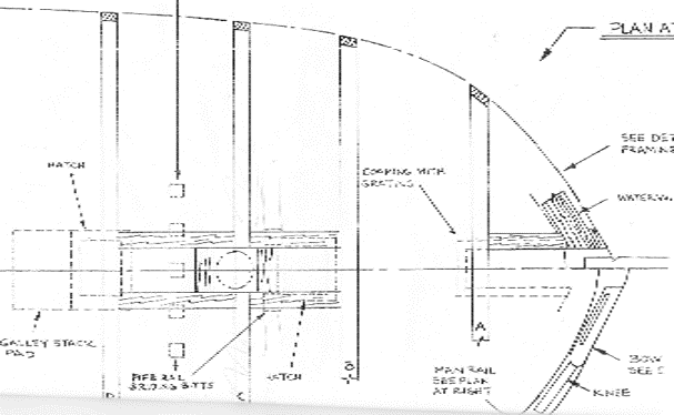
Finally, using the US Navy plan No. 022-06-2011 - Diagonal Rider & Knee Layout Revised 2011 (a minor revision of 27772, 1996) for the elevation view and No, 17636 Spar Deck Planking Removed 1926 for the plan view, I fabricated and added diagonal knees to the bulwarks around the gun ports of the rigged guns. Additionally, the three vertical stanchions around the stove were also fabricated from 0.032” music wire (for rigidity) and installed. Before I can move aft to the next section and while the gun deck is still accessible, I want to create spare deck structure to ensure the foremast will have a 3° rake when it is installed. As I have it presently planned, this portion of the spar deck is expected to be planked.IMG_1479.HEIC

-
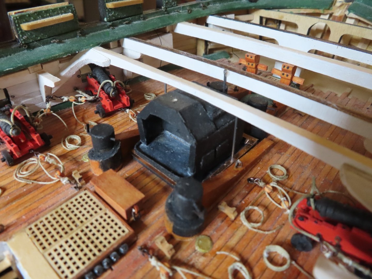
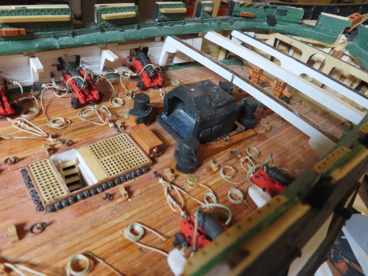
At this point, As I promised, the gun deck is becoming quite cluttered. I wanted the ship to look more like a working ship than one on display for the “Brass”, so no pretty coiled rope spirals.

-
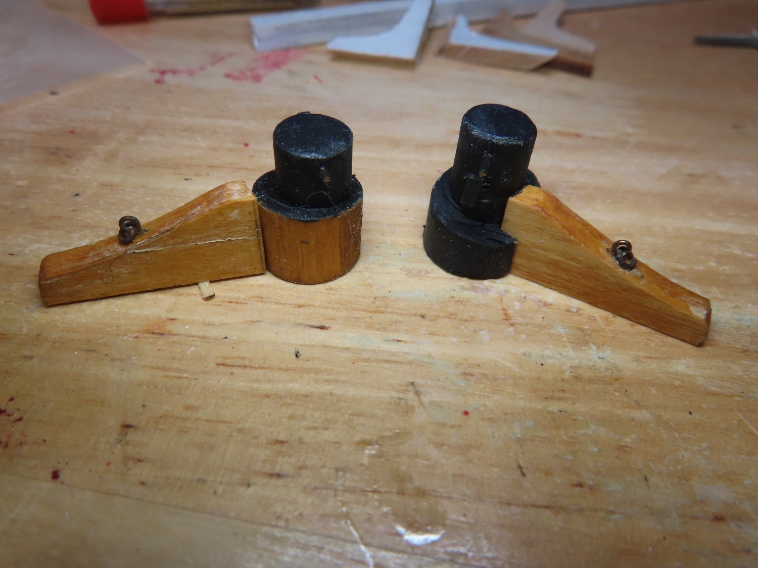
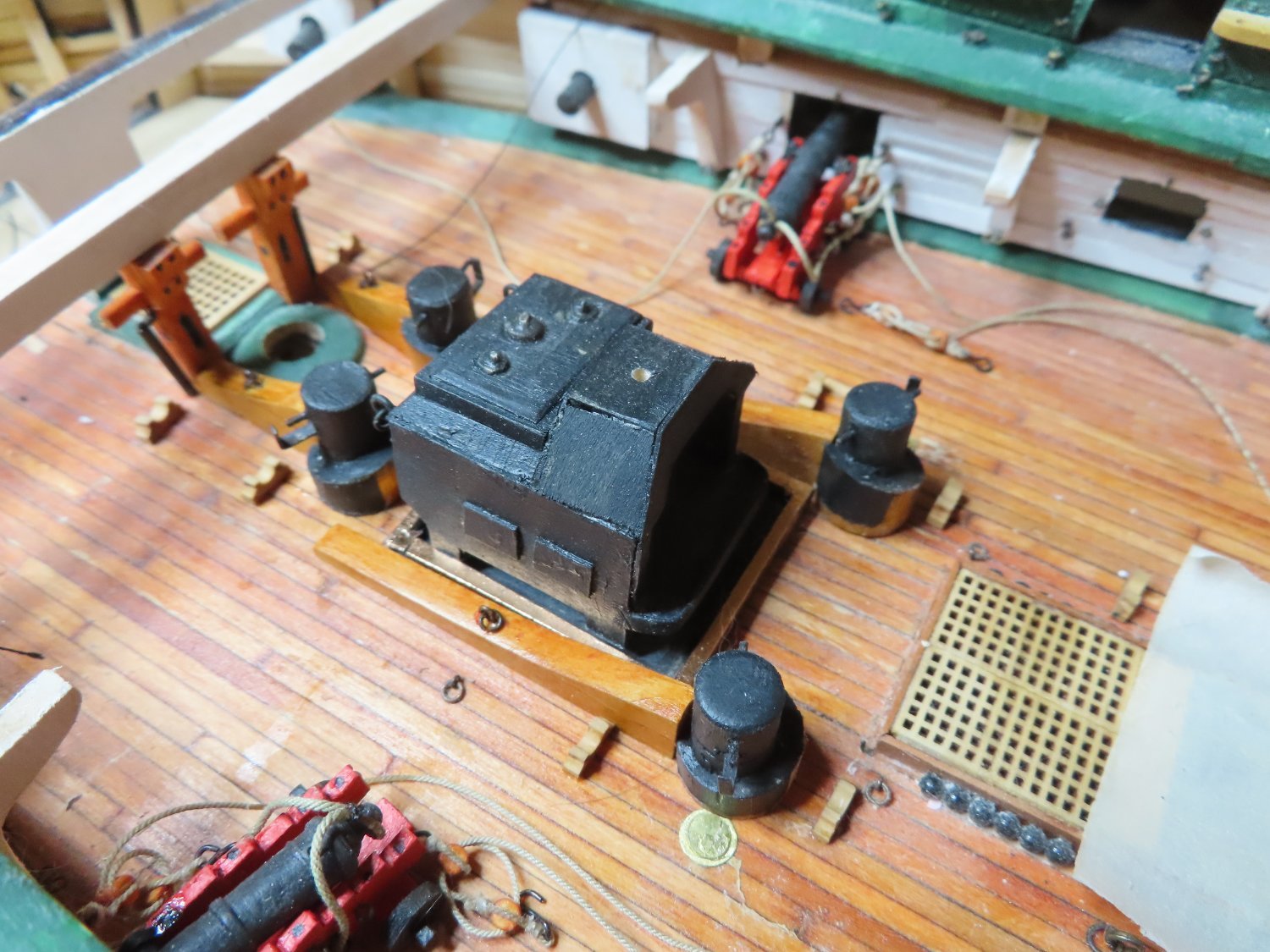
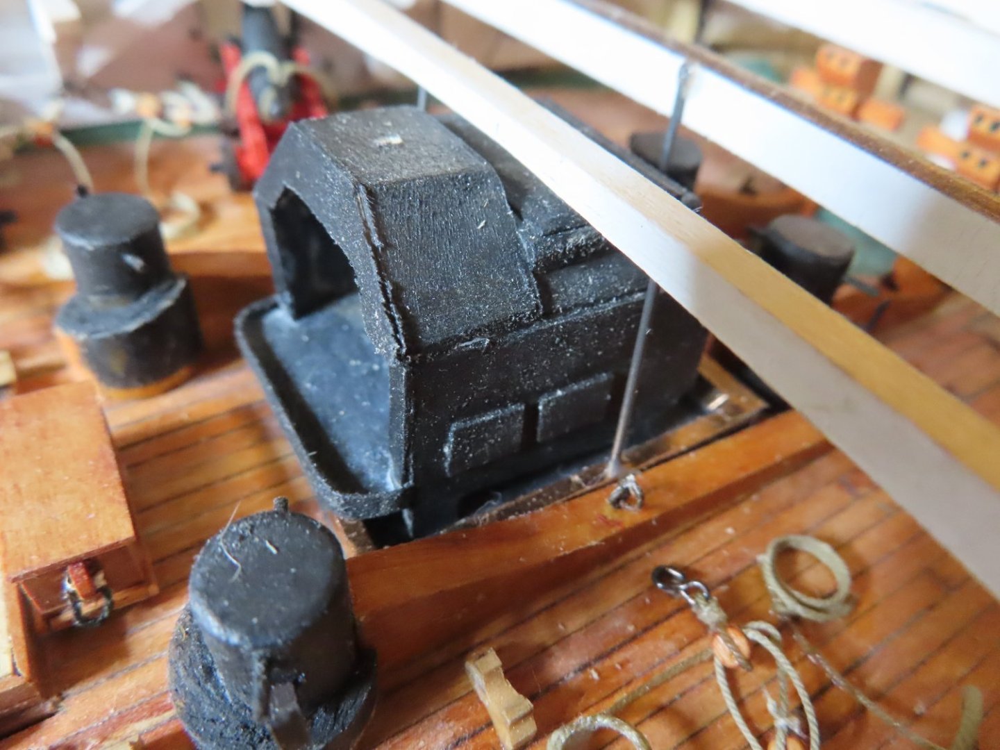
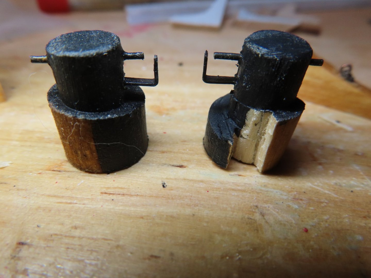
Then the next items to be installed were the anchor line bits and the stove with the stove tray which were previously fabricated. These were installed after dry fitting their final position and installing the spar deck beam that passes over the stove (not shown).


-
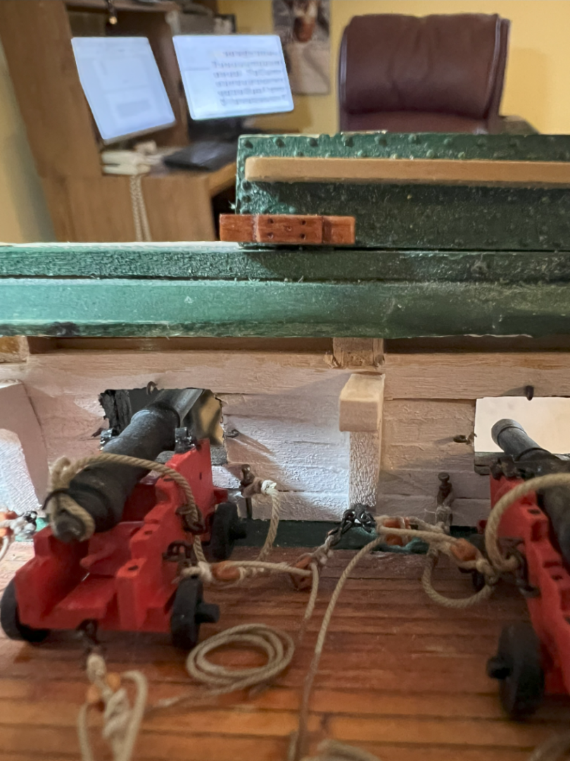
Moving aft, the gun rigs and recoil lines for three sets of guns after the dummy guns had to be fabricated. The three gun sets of fully rigged guns were glued into position with their recoil ropes secured to the bulwark with a small nail through two eyebolts. I initially planned to trim the nails so that they would be shorter and have a blunt end to more closely resemble the actual pin. This proved to be very difficult to use when attempting to thread them through the eyebolts and looped recoil rope. I just used the plain nail utilizing the pointed end to facilitate the installation to the bulwark. You would need a sharp eye to notice any difference.
-
If I remember correctly, Mr. Hunt planks one whole side, then does the other. I alternated back and forth every "band" in order to ensure my strakes mirrored each other. Jon