JSGerson
-
Posts
2,646 -
Joined
-
Last visited
Content Type
Profiles
Forums
Gallery
Events
Everything posted by JSGerson
-
 On your question on hammocks, have you seen Usetosail's build? He used Sculpey and I think they look great. As for photos or info, I have nothing to add to the photos I already sent you. Jon
 -
I just got back from visiting my Sister in Connecticut for Thanksgiving Week so I am now just getting caught up. You stated that you harden 0.012 brass wire by stretching it. How did you do that? Is there some jig involved? How much stretching is required and how do you know when you've done it? Would music wire worked? It's already very stiff (no stretching required) as well as colored dark (black?) or is it too stiff? Thanks Jon
-
You do what you feel is best for your model, after all, you are the model maker. Personally, I like the finer "rivets." It follows my model making philosophy; I want the viewers to discover more detail as they moved in closer. For example, when I added tree nails to my Rattlesnake, I did not do what many others did, increased the contrast of the nails so they would stand out to be seen. On a real ship they would almost blend into the planking. So the tree nails on my model become obvious only when the viewer is drawn in and they are greeted with more detail. By the way, you mentioned "melting." I assume that the tops of the fishing line are melted to flatten them into "rivet" heads. How exactly did you do that? My guess is you heated a piece of metal and pressed it on top of the fishing line creating the "rivet." Jon
-
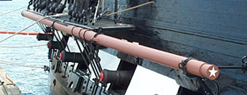
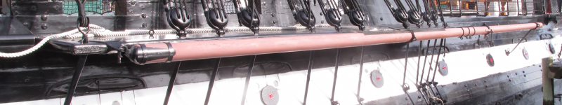
I'm getting close to finishing my current build, Rattlesnake so I am quite interested in watching others build their Constitution, my next build. My original plan, based on the Robert Hunt's practicum, was to use Tichy Train Group 0.02" dia rivets (No. 8017), but your idea using fishing line is a whole lot cheaper and has the same effect. Having looked at photos of the ship's bulwark rivets and comparing them with your mock-up, it appears to me that if you use fishing line half as thick as the 30 lb test line, that would really look more accurate. But I don't know anything fishing line so I don't know what kind of line that would be or how easy or hard it would be to work with. Good luck with your efforts Jon
-
Two fine looking boys and one very proud Grandpa; congratulations! Just make sure you have a very strong display case for the model when you bring it to their house...just saying 8-) Jon
-
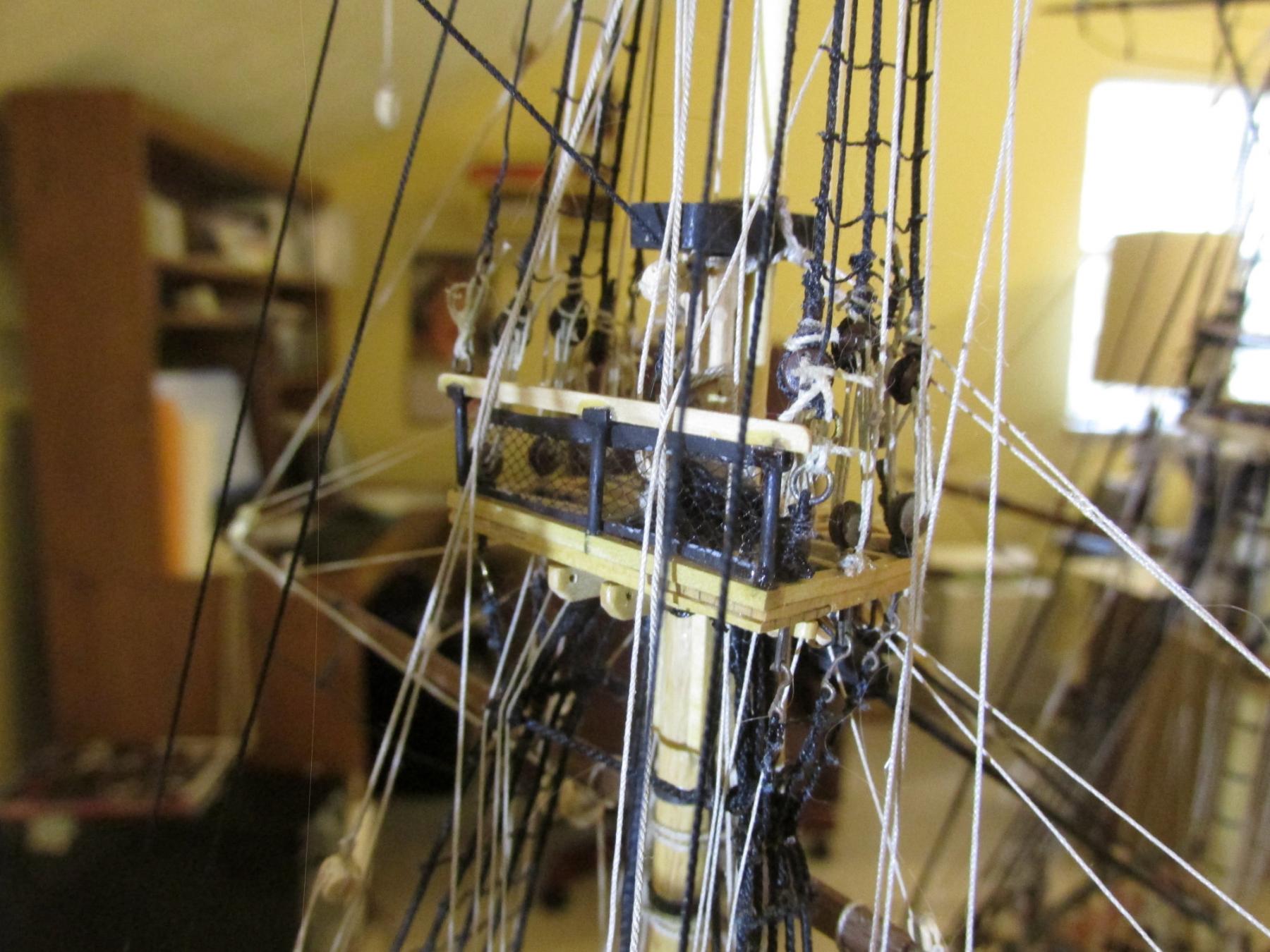
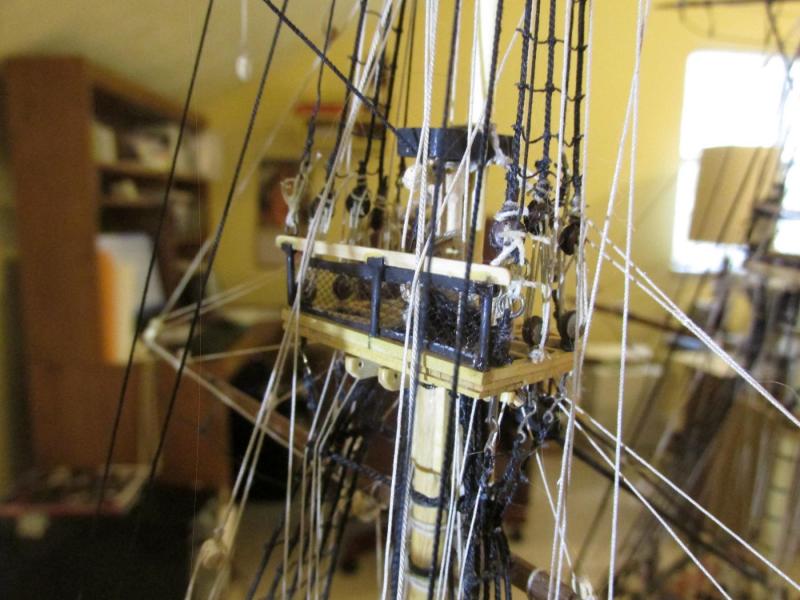
Beautifully done netting on your Battle Station. I actually thought about doing something similar but the scale was just too small for me to handle. I have no idea what the netting (if it existed at all on the Rattlesnake mast tops) scale/spacing should be so I used what material I had. It seems to work. Jon
- 974 replies
-
- 2
-

-
- rattlesnake
- mamoli
- (and 1 more)
-
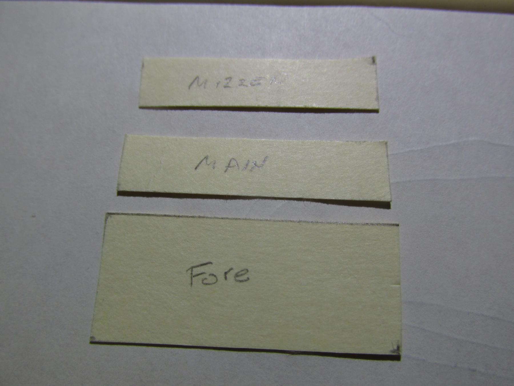
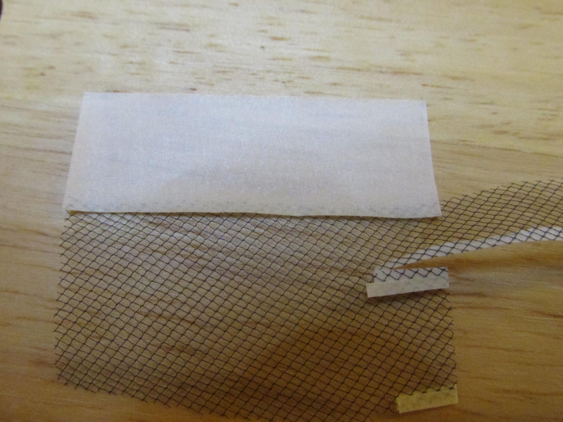
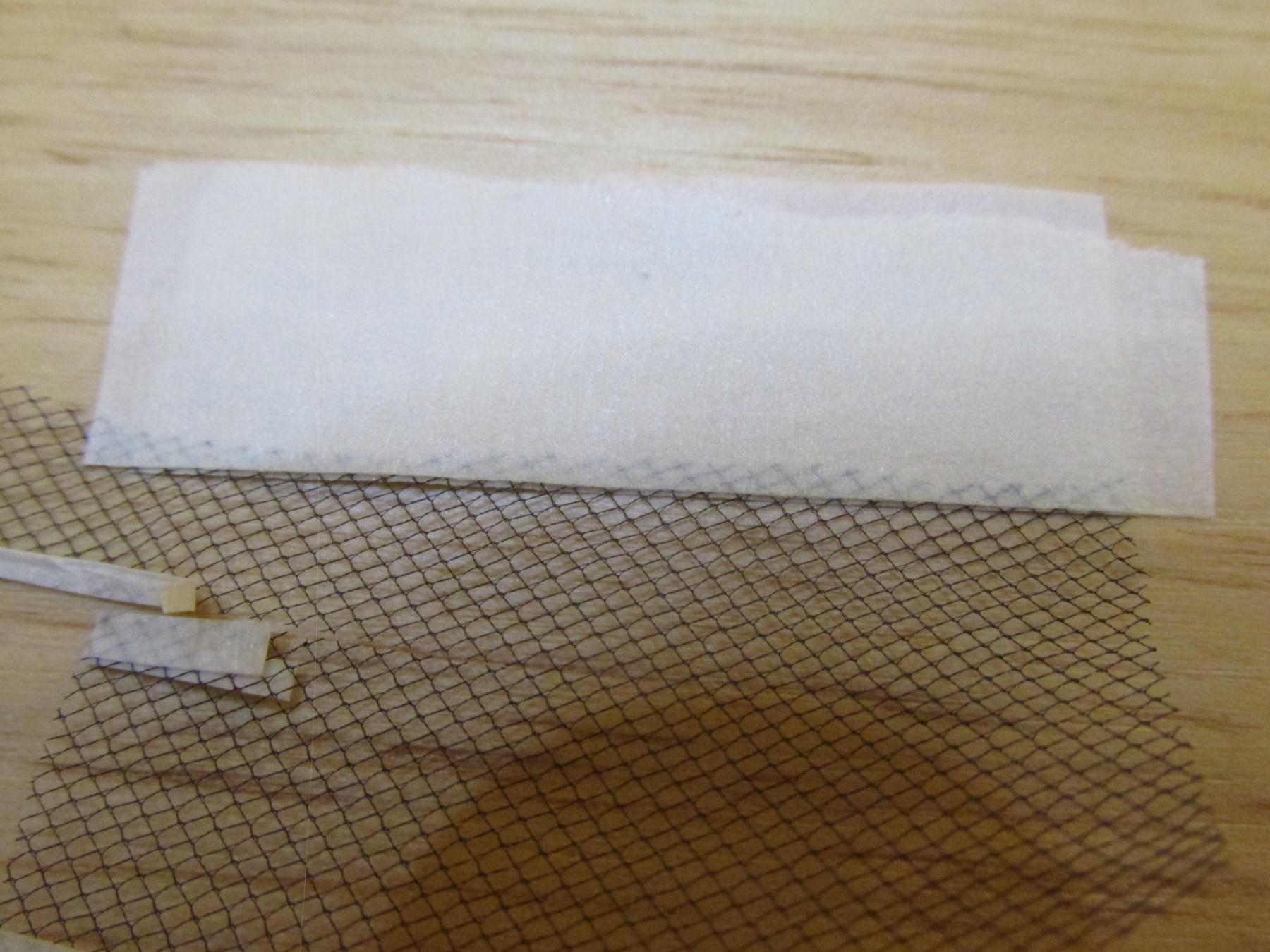
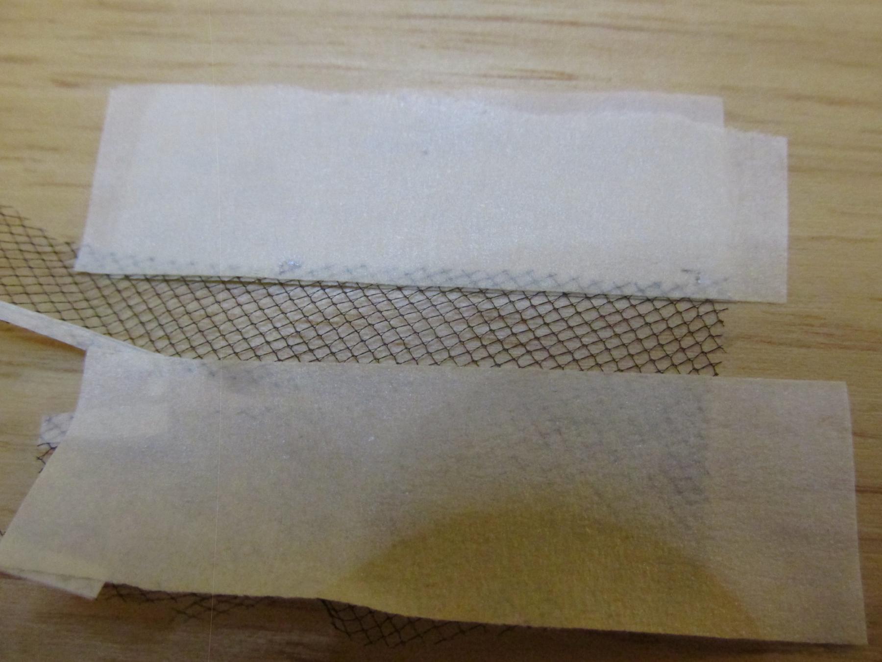
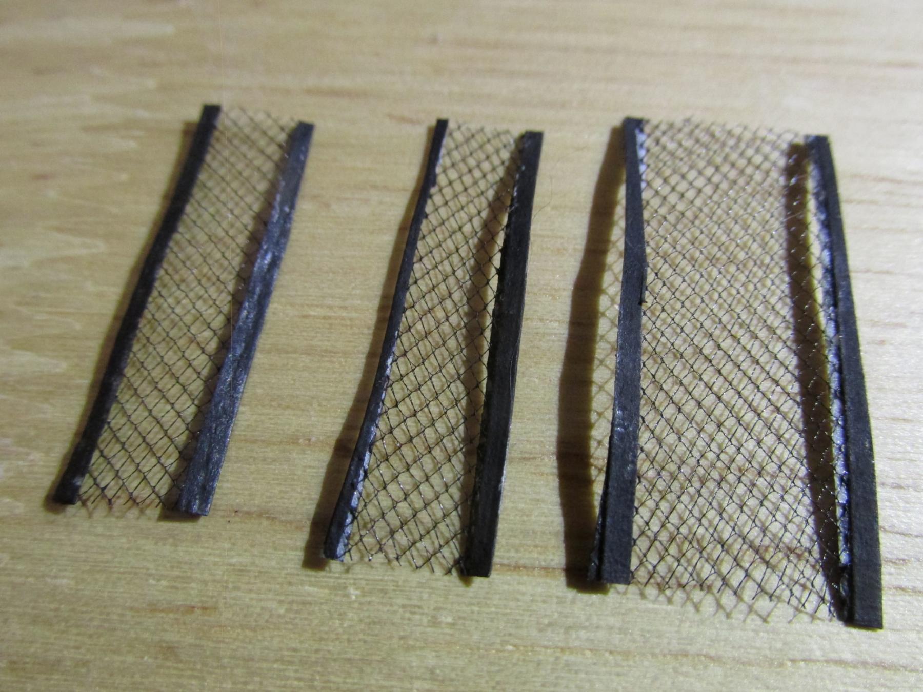
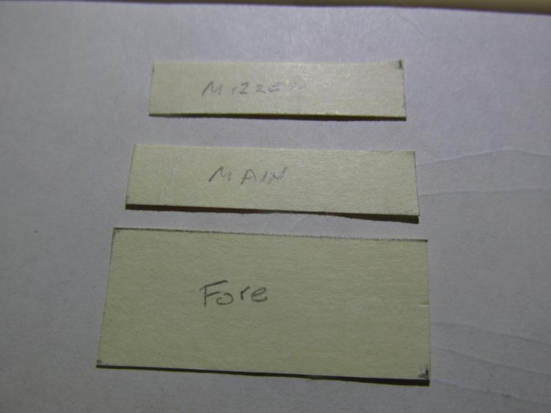
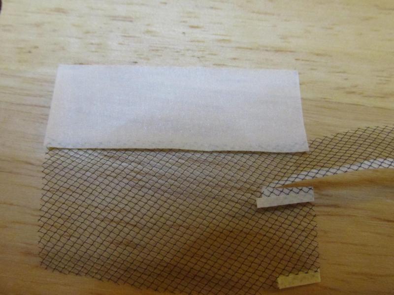
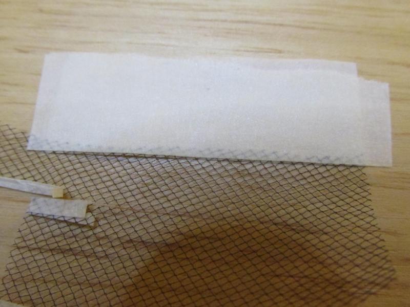
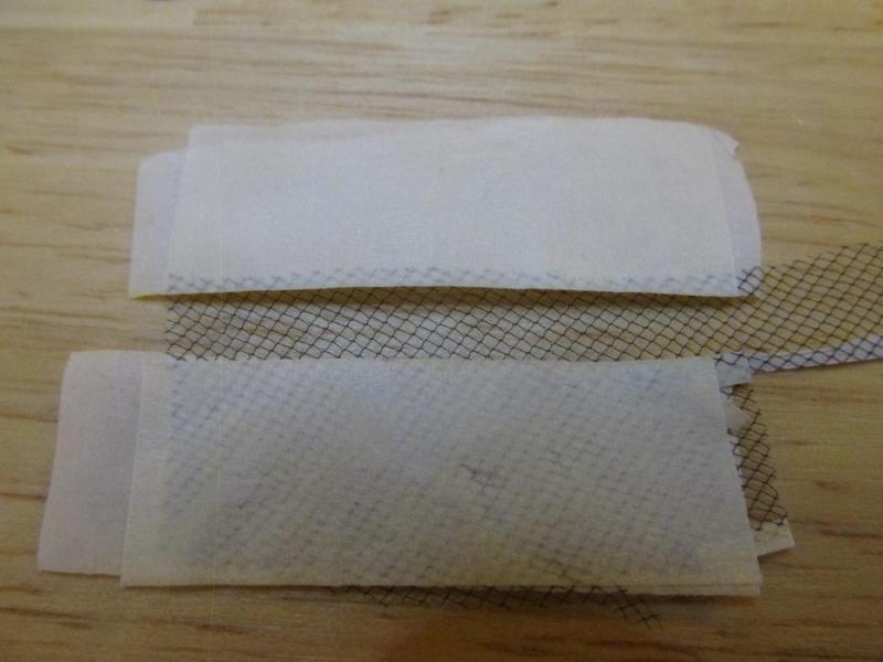
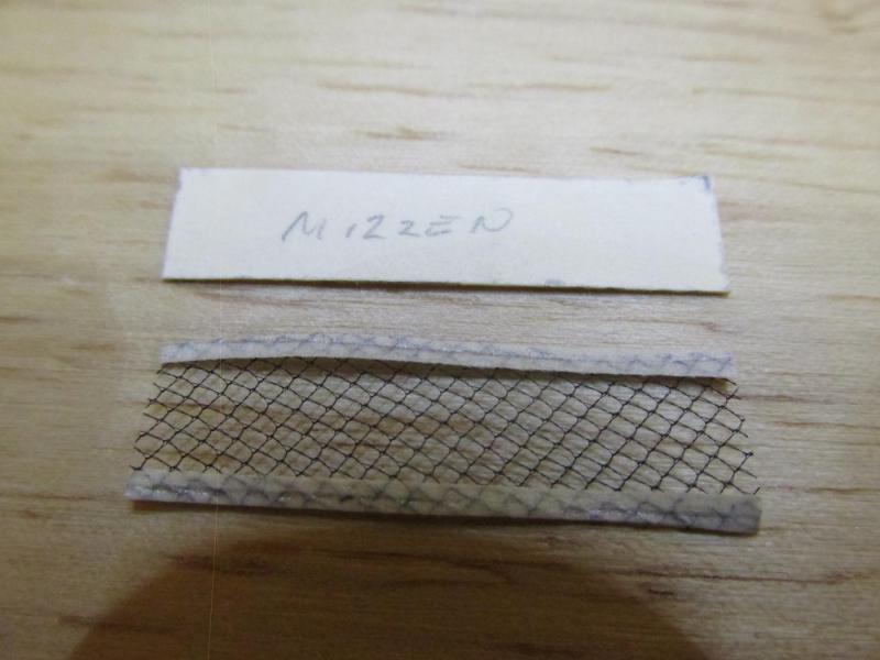
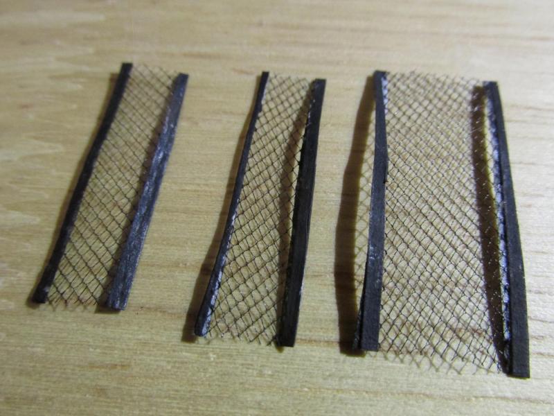
In addition I went to the NRG Convention in San Diego CA. The hotel was a couple of blocks from the waterfront where the nautical museum was as well as other activities, so it was well within walking distance. The weather was perfect, the convention was great, and I was exhausted by the time I got back to South Carolina. Unfortunately I had to take the” redeye special” flight (no other choices) so I was up for 36 hours from the time I got up Sunday morning till I arrive at home Monday around 11:00am. I tried to get some shuteye on the plane but those seats are not designed for sleeping. I next wanted to add rail netting to the mast tops before I continued with the rigging. Neither Mamoli’s nor Model Shipways’ instructions addressed this so I had to wing it based on what I saw some other builds. Using the same black tulle I used on the bowsprit netting, I made some aborted attempts trying to figure out how to attach it to the railings. What I finally came up with seemed to work. First I made a netting template for each top as each was slightly different from each other and cut the tulle to shape for each. Tulle is very flimsy and does not hold its shape well; it will distort at the slightest tug. I had noticed on actual ships where netting was used, the netting had a boarder, be it rope or canvas or something, where the lacing was attached for support. Using masking tape, I taped the long edges of the tulle, flipped the tulle over and taped again matching the first tape now on the now underside. Then I trimmed the tape so that only a thin strip remained all the while matching the shape and size of the template. The tape strip was then painted black. Finally the netting was slipped into place and glued with GS Hypo Fabric Cement. It has the consistency of “airplane glue,” dries transparent, and is flexible.

- 974 replies
-
- 10
-
-
- rattlesnake
- mamoli
- (and 1 more)
-
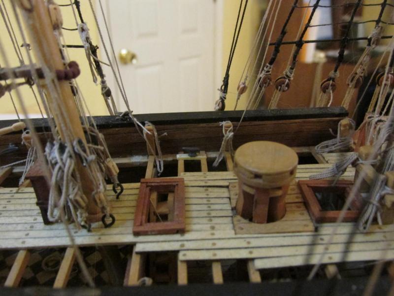
Wow, has it been almost 6 weeks since I last updated my log? Well the progress I’ve made really does not reflect the lapsed time period (as usual). In order to add the belay pin and cleat rope coils, I first wanted to tighten their respective lines. In doing so I found that some lines went to the wrong pin or cleat and others were twisted around other lines. That all had to be corrected before the coils could be added.
- 974 replies
-
- 8
-
-
- rattlesnake
- mamoli
- (and 1 more)
-
Depending on the wood the dowels are made of, they can be easy or hard to work with. For my Rattlesnake I believe I used the kit's dowel for the lower portion of the masts, the rest I used square stock boxwood which worked well. For the yards, because my model was all natural wood, I used walnut I cut myself because I needed them dark. I avoided basswood which I find too soft and it doesn't sand as smooth and clean, or hold an edge as boxwood. Because the masts and yards are round, square, and octagonal in cross section at various points, I found it easier to shape square stock than round. Jon
-
Sorry for the redundant question on the masts. You've accomplished so much in such a short time I had forgotten that you did describe how the masts were assembled back in April. I had to go back through your log to refresh my memory. Thanks for being patient with me. Jon
-
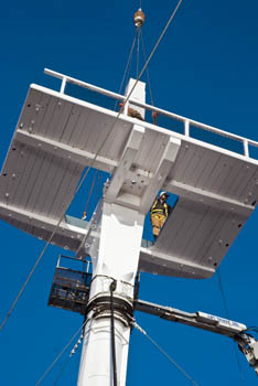
Those tops look great! How did you create the half bands on the lower part portion of the masts and what did you use for the bands in the square upper part? I'm trying to gleam all the detail I can for when I start my build. Just realized, I hope you didn't glue the caps on, they need to be removed to add the second step masts! Thanks Jon
-
I had the same choices you did when I started rigging my Rattlesnake. Having never rigged a three masted model before, I looked at what everybody else did. The Robert Hunt practicum I was following used the "rig the masts and yards off the ship" method. The book I was also following by David Antscherl, The Fully Framed Model, Rigging a Sixth Rate Sloop of 1767-1780 was a "do as much as you can off ship and install it on the ship" method. By this I mean most of the blocks and some rigging were installed on the mast and yards off ship while the most of the rigging was installed on ship. In addition the rigging sequence more or less followed the actual building sequence of a real ship. Each method has its own advantages and disadvantages. One Rattlesnake builder I was following was also using the practicum and he felt the practicum rigging instructions wasted too line. Since I was using Syren's rigging line and not the Mamoli kit's, cost was also a consideration. I installed the bowsprit first, then work my way from the first level of the masts from the mizzen forward, adding the associated rigging for each step level, inboard to outboard. I worked for me, but since this was the first time I had ever done this, I have no previous experience to compare it against. I think you made the right choice for you. You do what works best for your knowledge and skills. Jon
- 57 replies
-
- 1
-
-
- rattlesnake
- model shipways
- (and 1 more)
-
Here are some of the pictures I had hoped you would of received full size by now Jon

-
Sorry it's taking so long to reach you. I thought about attaching the netting on my Rattlesnake at the same time you are now but a lot of other builds I was watching elected not to. They were afraid the netting would interfere or get damaged during the rigging process. Of course using the method you are using, you would have to do it now unless you can attached the rails later. My netting is going to to be laced on using a thread to wrap around the railing and stanchions and through the netting. . Once I finish adding my rope coils to the pin rails and cleats, that's next. At least that's the plan. BTW, what method did you use to add those fine "rivets" to the tops? Jon
-
I asked because I've seen other builders (myself included) "cheat" and use served music wire. You can't tell the difference and it looks taught all the time.
- 481 replies
-
- 1
-
-
- rattlesnake
- model shipways
- (and 1 more)
-
Those catharpins are a real bugger to install especially trying to get the tension consistent on all of them. Would you mind elaborating how you accomplished it?
- 481 replies
-
- 1
-
-
- rattlesnake
- model shipways
- (and 1 more)
-
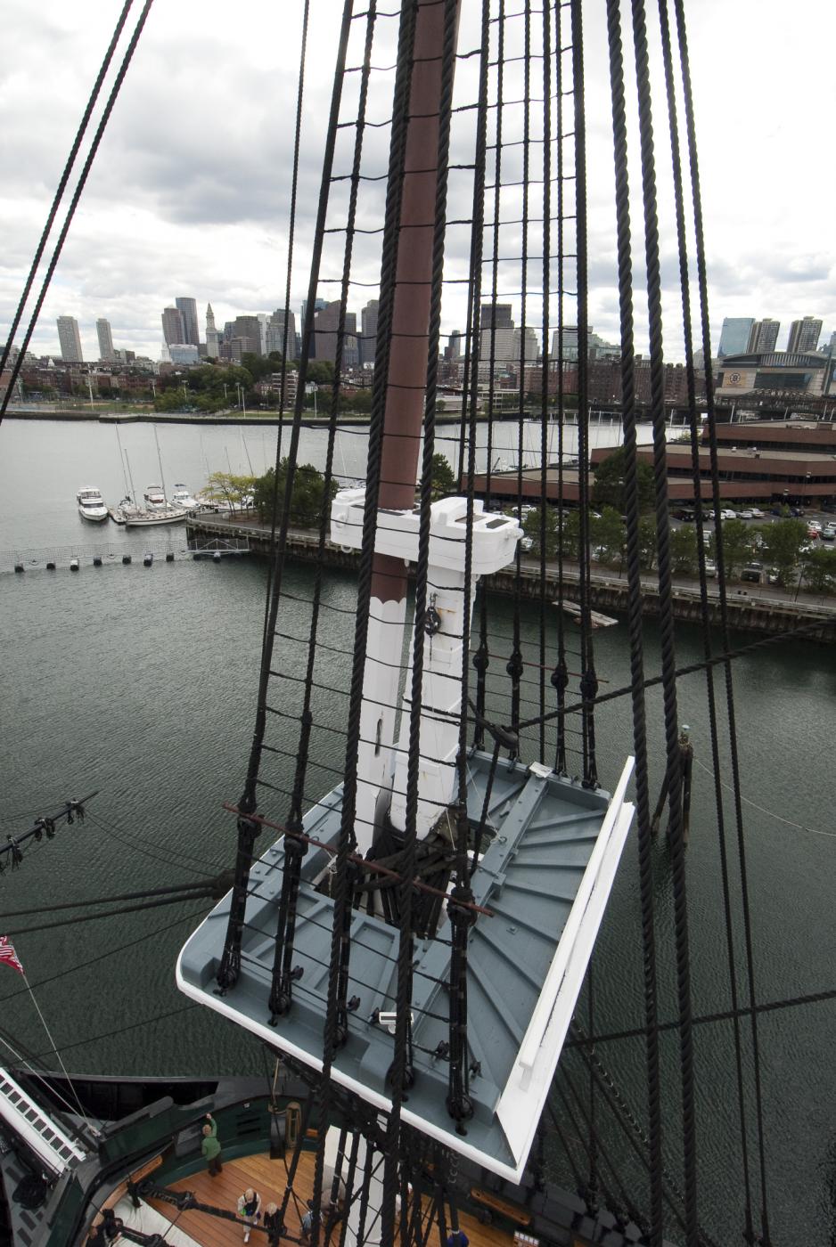
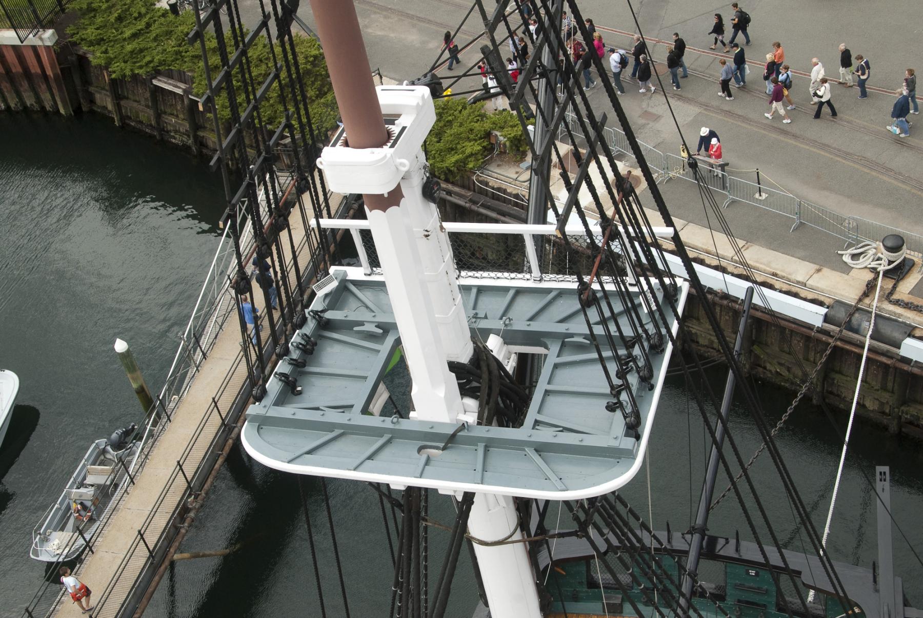
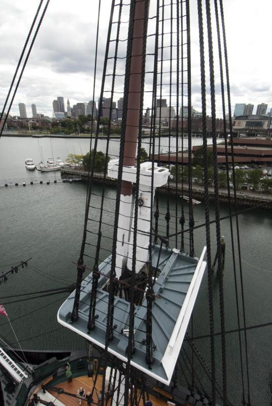
Beautiful work. I sure hope my disc with pictures and plans arrives before you finish the tops. When you get it, if you will check the folder under Photos, Masts, Fighting Tops you will find a bunch of photos taken from above as well as from below. Hopefully they will show you the eyebolts you are looking for. The Navy Plans "masts,21162" folder has a sheet of plans (21162 - Tops for Masts) for the tops which shows eyebolts.There are also a couple of miscellaneous documents related to the tops in "mast" folder.
-
Ken, you might want to try wetransfer.com. For no cost, you can transfer 20 GB of files. You submit your files to the site. The site notifies the recipient so they can download. After 30 days the stored files will vanish from the site. It worked great when my sister had send me a bunch of stuff. Jon
-
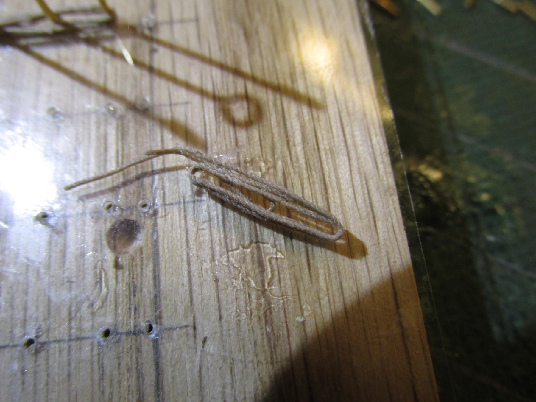
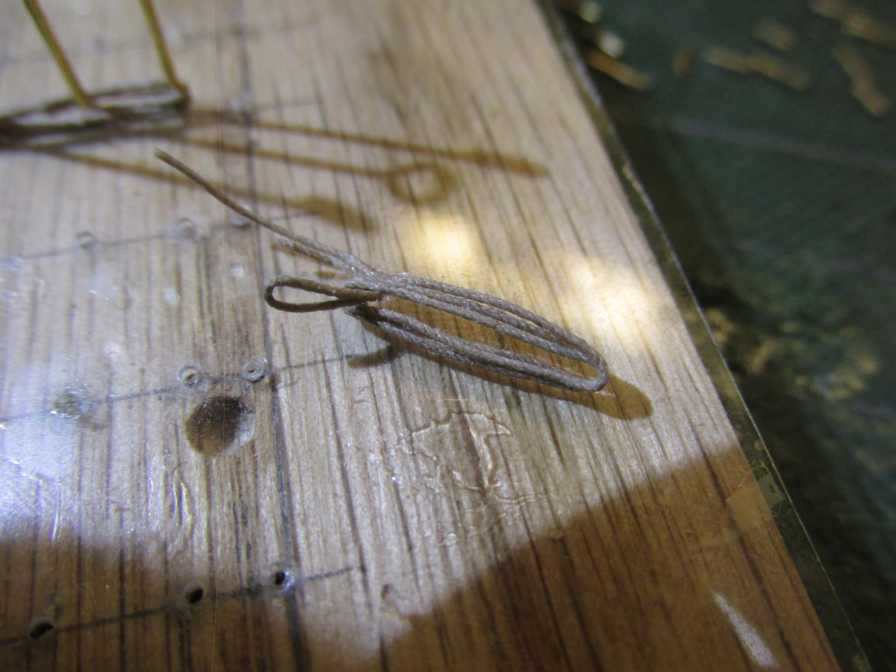
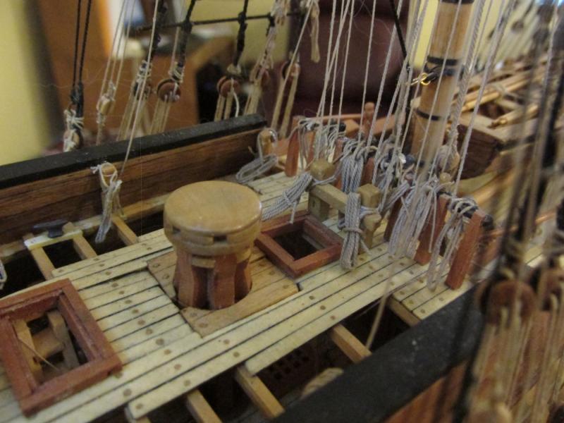
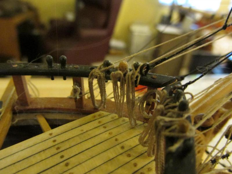
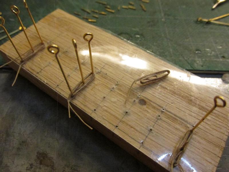
Once the glue has set, the pins are removed and the coil pops off the plastic with a little coaxing from an X-acto knife. The short loop at the center of the coil is pulled through the coil. The excess line is trimmed and the loop is then hung on the belay pin with the coil hanging straight down. Ta-da!!


- 974 replies
-
- 11
-
-
- rattlesnake
- mamoli
- (and 1 more)
-
On a model, this is done in two parts; the line terminates at the pin/cleat and then a separate coil is attached hiding the excess free ends of the line. To make a pin coil that looks like the real thing a jig is required; mine consists of three pins in a piece of wood. The block of wood has a piece of plastic on it so the line won’t stick to the wood block. It makes the hanging loop and the coil from one piece of line. First the line is soaked in water for a few minutes. A dab of PVC glue is placed on my fore finger and thumb. The wet line is pulled through my pinched fingers coating the line and drawing off any excess glue. Using the jig, the line comes in, loops around the middle pin, crosses over itself and rounds the top pin, then down to the bottom pin. It continues around the top and bottom pins a couple of times.
- 974 replies
-
- 7
-
-
- rattlesnake
- mamoli
- (and 1 more)
-
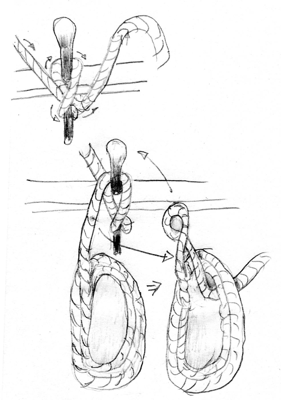
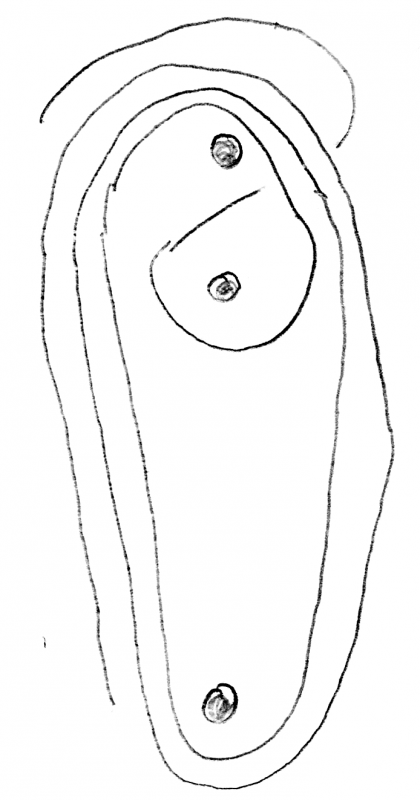
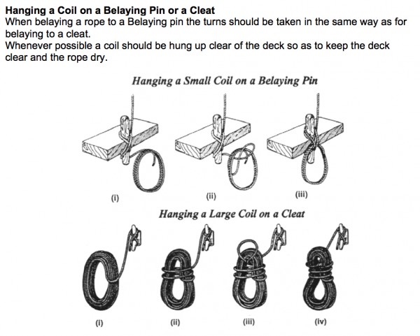
I’ve started to clean-up the “spaghetti” and add pin rail rope coils. The coils that hang on the belay pins are not just coiled around the pin; many times the pin is just not large enough to hold all the rope. The coil his hung from the side of the pin. The same is true for cleats. I found this diagram some time back (don’t remember where) which hopefully is self-explanatory. I also added my own crude drawing.

- 974 replies
-
- 9
-
-
- rattlesnake
- mamoli
- (and 1 more)
-
Thought you might want this picture of the center balustrades where the arches meet. Jon

-
"Soon" is a relative term. I've been working on this model since 2009. I do however see the the light at the end of the tunnel. When I pop out of the tunnel depends on Mr. Murphy and his laws. 8-) Jon
- 974 replies
-
- 4
-
-
- rattlesnake
- mamoli
- (and 1 more)
-
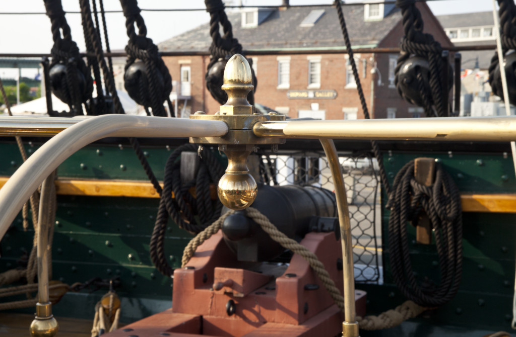
I thought I had seen a master craftsman make brass stanchions before when I saw Blues Ensign make them for his Pegasus, but I believe you sir, will surpass that standard. Beautiful work! Jon
-
The best I can come up with are these photos...and you have to look real close. Jon