JSGerson
-
Posts
2,646 -
Joined
-
Last visited
Content Type
Profiles
Forums
Gallery
Events
Everything posted by JSGerson
-
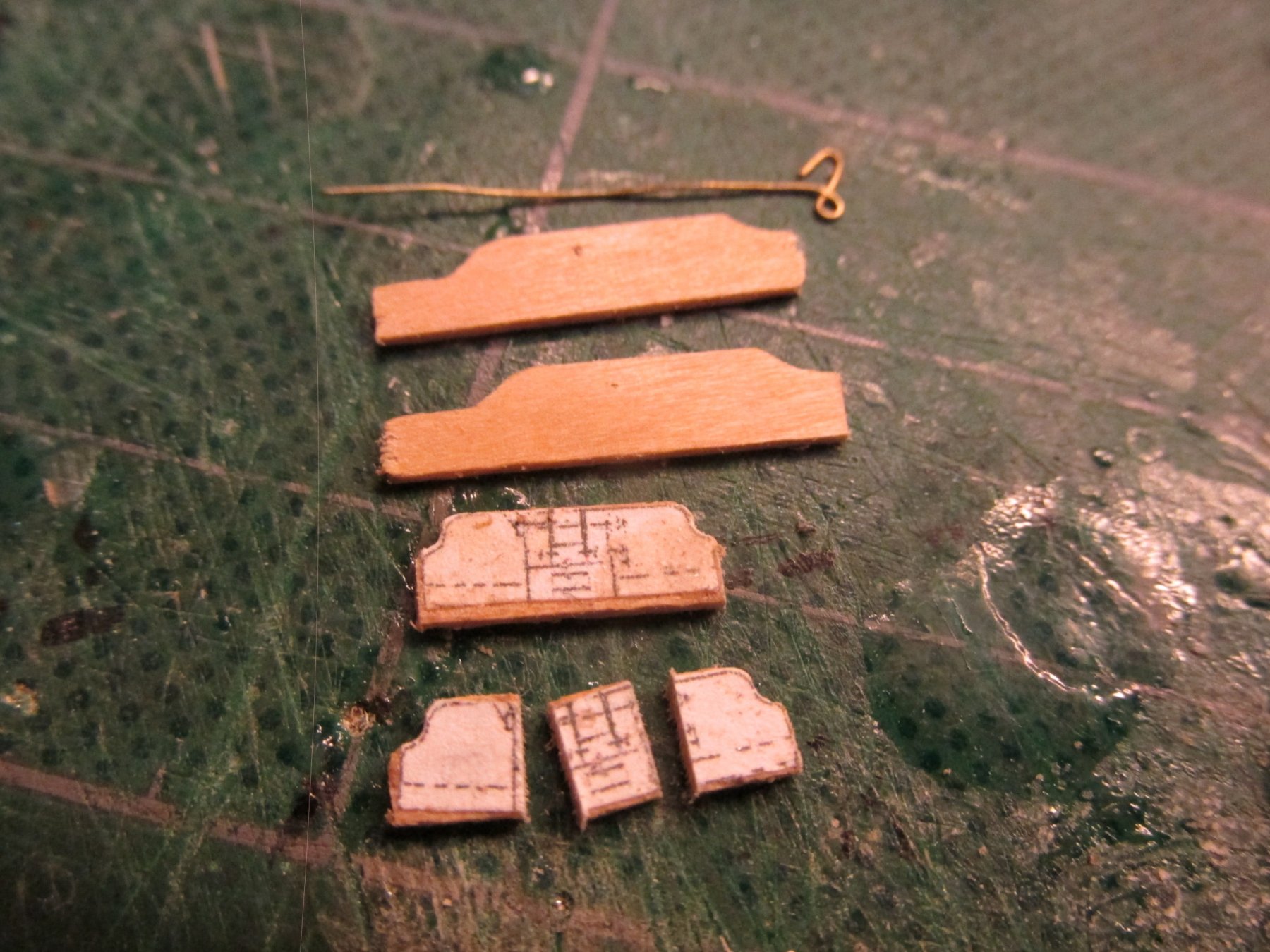
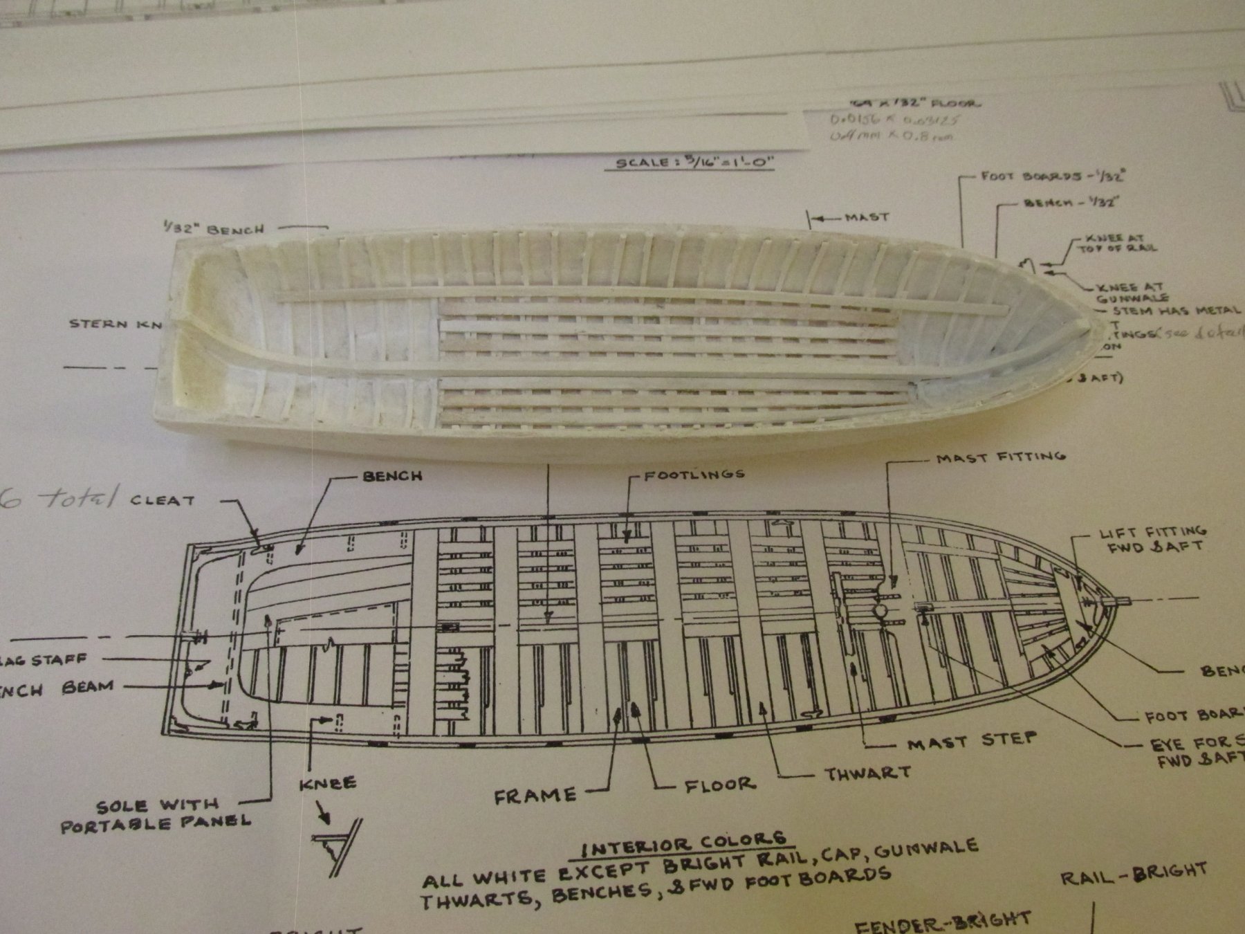
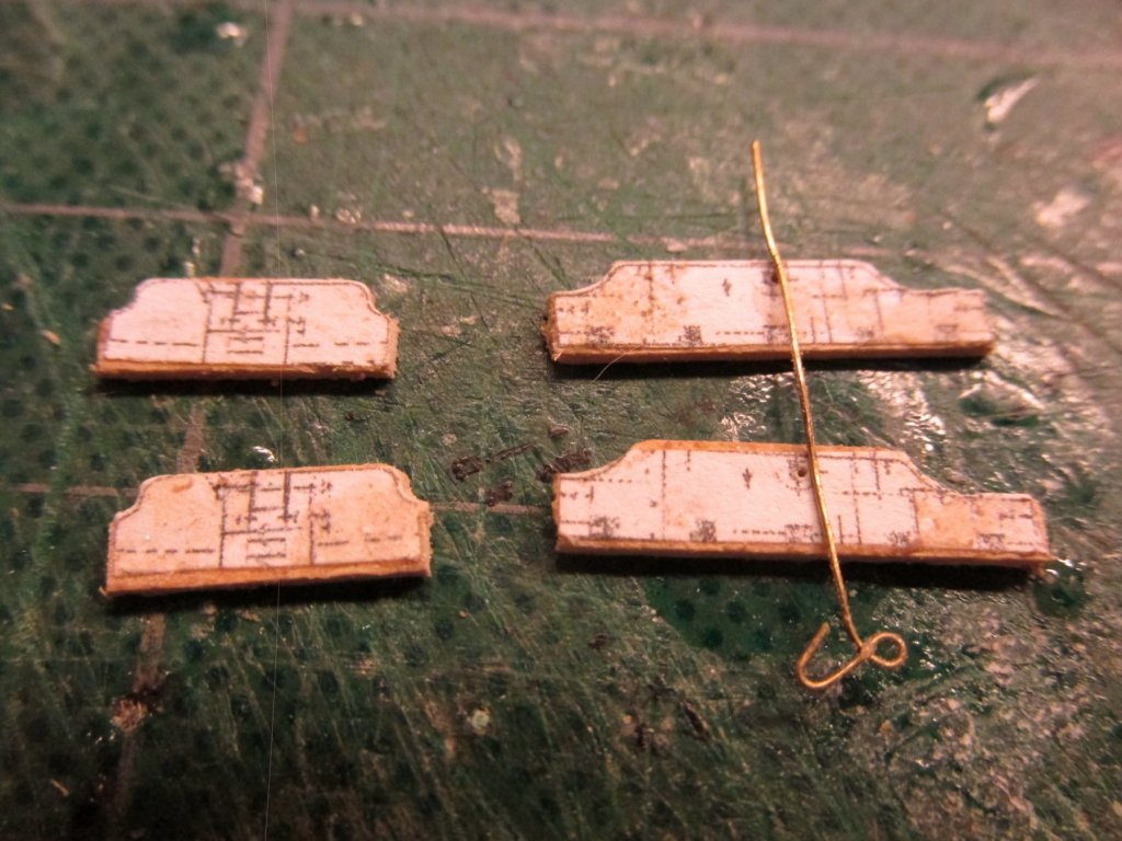
 Pinnace Stern Sole Being a landlubber, I’m was not familiar with boats when I started building these models. So once again, I’m modeling something I have no knowledge about. I’m referring to the aft end on the pinnace, something called the “sole.” This appears to be a floor section of the boat and in this case, one with a portable panel. I’m not certain as to sole’s purpose, but I assume the portable panel is there to gain access to the area below it. The practicum simulates the sole with a piece of styrene etched with lines imitating pieces of wood. I’ve seen others use 1/64” plywood and do the same. I thought I would try something different. Using individual pieces of 1/32” basswood, I reconstructed each piece of the sole as best I could. First a pattern was made based on the plans, but adapted to conform the actual model. This was used to size the pieces and orientate and locate their final position. The problem was that the sole required that the piece be glued edge to edge. This is not structurally strong. To compensate for this lack of mechanical strength, the pieces were PVC glued directly onto paper in five separate groups.
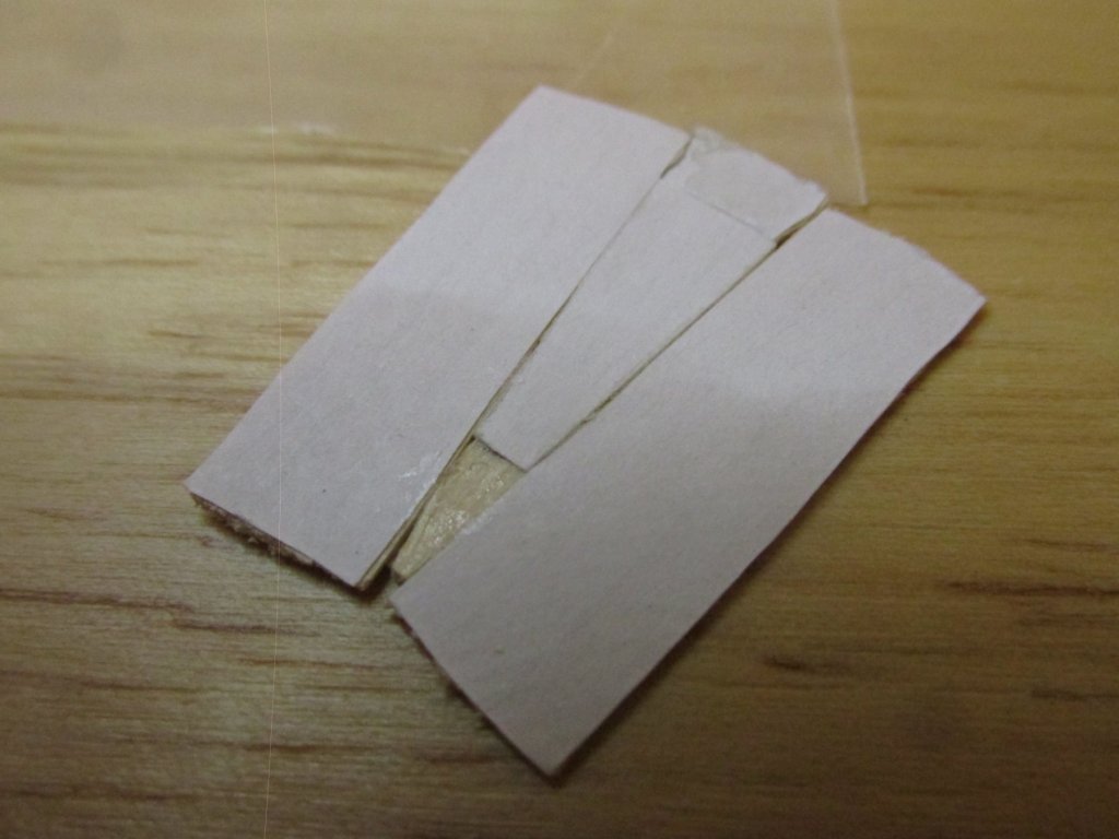
-
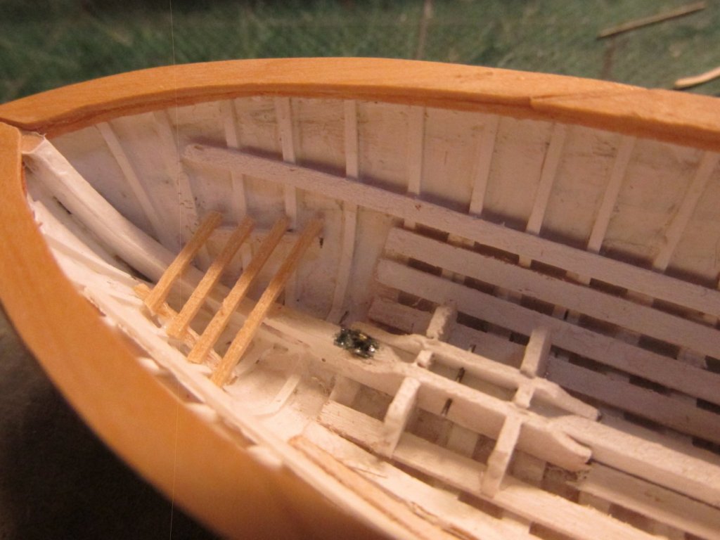
Additionally, everybody (those that I can see) installed 5 footboards radiating from the bow. I counted seven on the plans. So, I installed seven. Let me tell you, those pieces are small and only 1/32” thick.

-
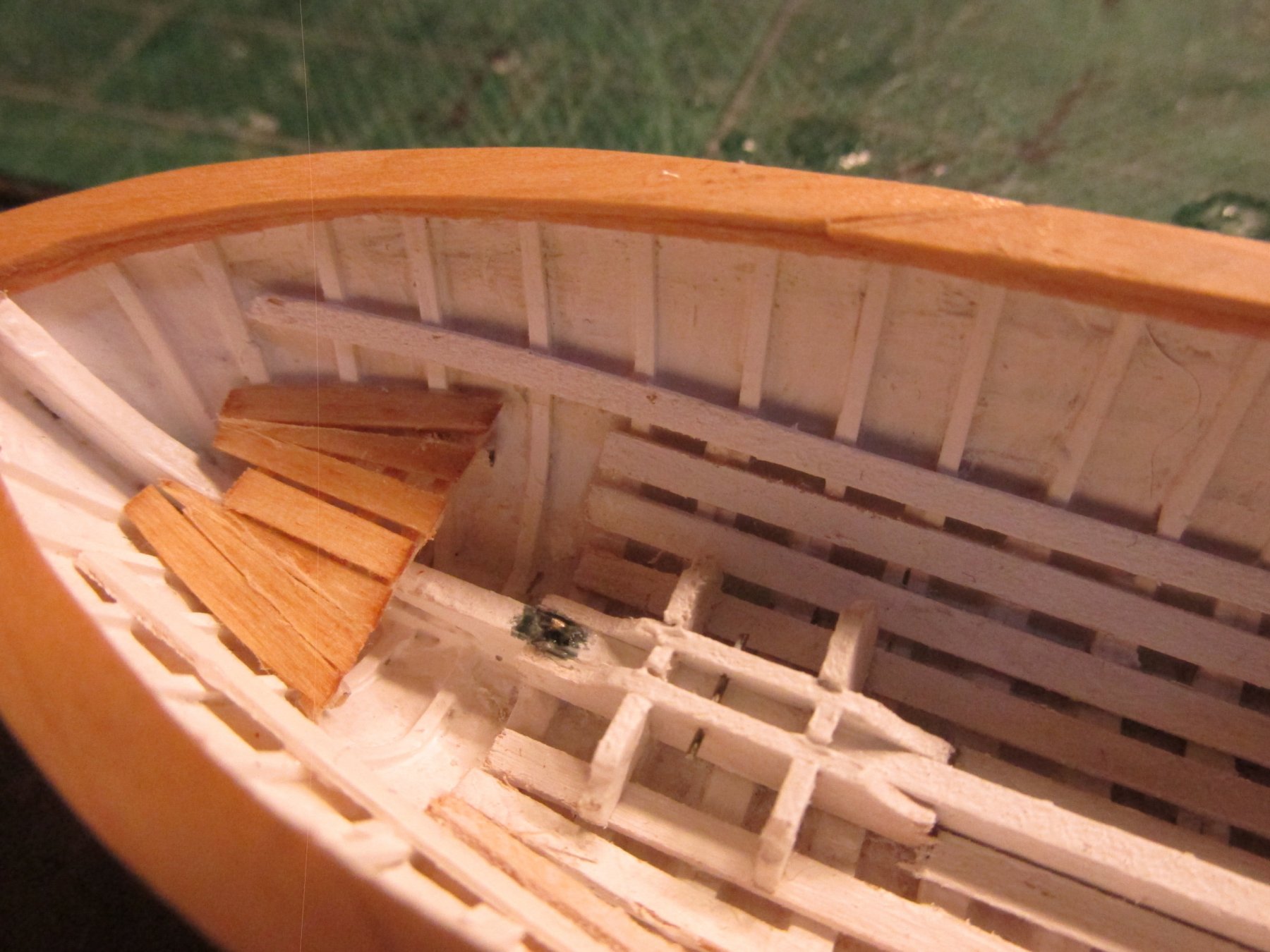
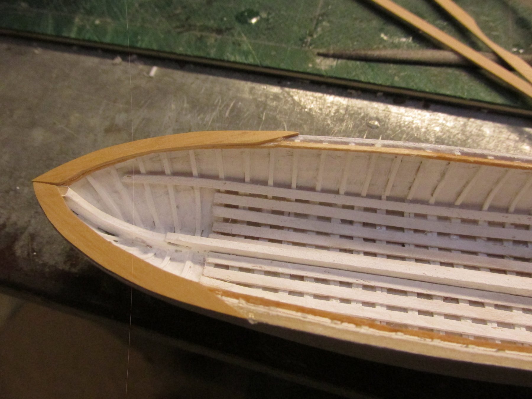
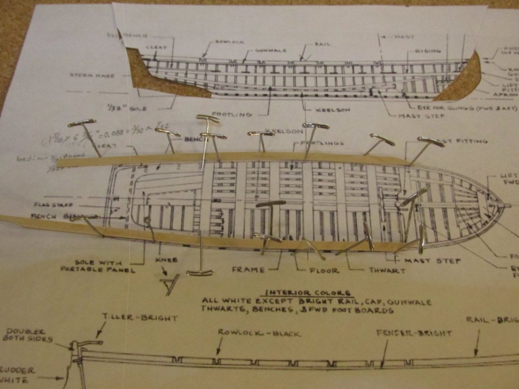
Pinnace Bow Footboards These are the short footboards at the bow. According to the Navy plans and the kit’s plans (although you’d be hard pressed to see the detail in their scale size plans), there are four 4 support members that pass over the keelson and supported along the inside walls. From those builders that have posted this detail, including the practicum, nobody has included them in their build. I did, even though you can’t see them when the model finished.
-
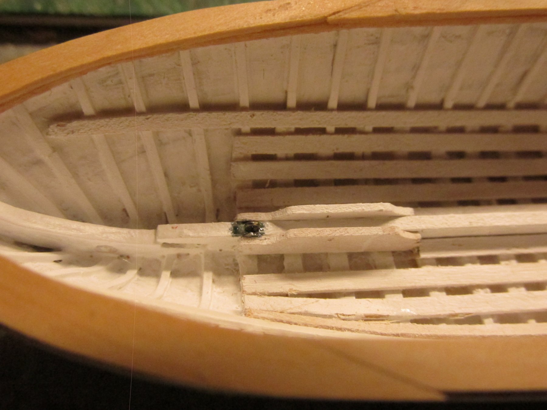
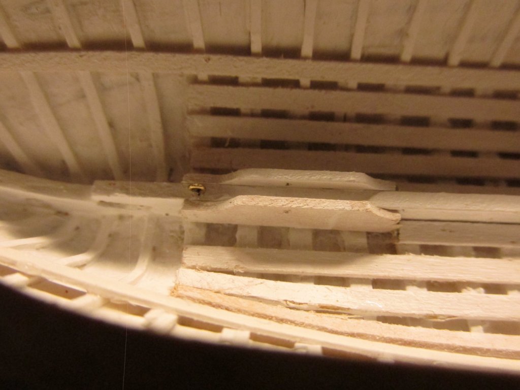
The pre-painted beam structures were glued in first using PVC glue so I could make small adjustments. At his point, I decided I didn’t like the copper wire for the bolt. I decided to sacrifice the #80 bit I used to drill the bolt hole as the bolt itself. It was stiff and had the right thickness and color. An eyebolt was required just forward of the step. The eyebolt was not shown a dimension on the Navy plans so I made some measurements off the plans and reduced it scale. It came out to be approximately 1/16”. Because the eyebolt was shown on a metal plate, I painted the bolt and a square area around the bolt black to simulate the metal plate. Finally, the cross structures were added, the two outer “wings”, then a filler piece in the center. A bit of touch up paint, and it was complete. The whole mast step is just ¾” in length.


-
Two of the pieces fit at right angles to the beam pieces and appear to sit on the floor boards. This is where I was confused. The plans state that the two beam pieces fit against the keelson. From the plan view, the cross pieces appear to fir over the beam pieces. The elevation view implies that they butt up against the beam pieces. My best guess is that this structure is constructed somewhat like a grating. Because this was going to be painted and was in a limited view area, I “cheated” and tried to make it look right, not necessarily built right. That license sure comes in handy.

-
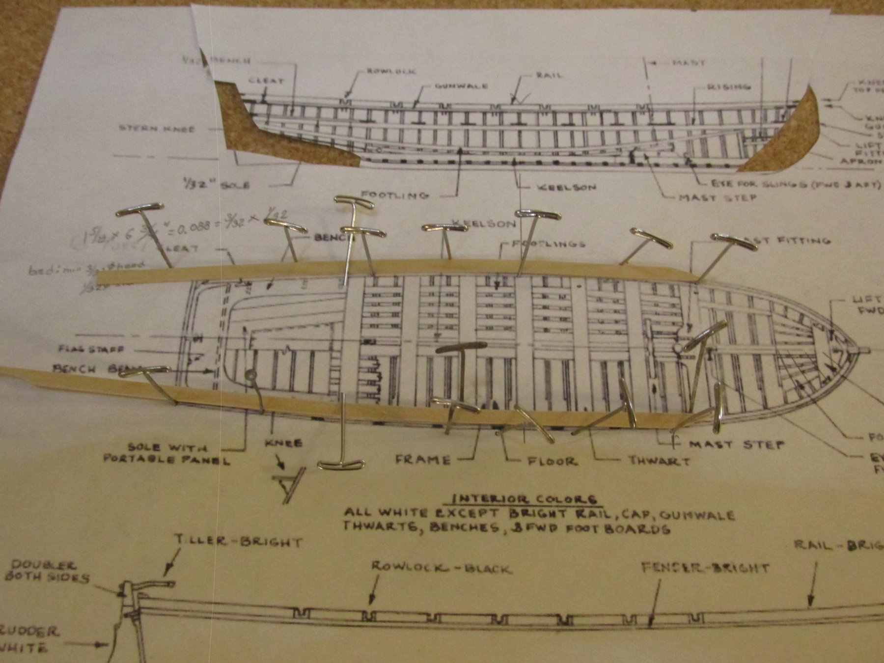
Pinnace Mast Step Now that the Pinnace’s interior shell has been completed, the interior structures can now be made. First is the mast step. As usual, my first order of business is to find pictures of the real thing and research how others made theirs. Try as I might, I could not find a single pictures on the internet nor in any of the books on the Constitution I have, nor in any of the books on small boats I have. I did have the Navy plans, but even those were a bit confusing. The practicum skipped this part all together. Of the 34 build logs I have collected, less than five devoted any detail or images as to how they did what they did for the ship’s boats. And of those, nobody followed the kit’s plans which mirrored the Navy plans, meticulously. As usual, just about everyone used artistic license to either skip a lot of details or alter the design for one reason or another. That was their choice and I have no problem with that. My choice is to try and follow the Navy plans as best I can. Using the Navy plans, the four main parts of the mast step were reduced to scale and used as a template. The plans call for a 1 inch bolt to pass through the two beam structures. This would also pass the curved bottom mast so that the mast could pivot along the length of the beam of the boat. A 1 inch bolt reduces to scale of 0.013” or the same as a #80 drill. Any of the images I’ve seen of other builder’s boats, their bolts appear to be thicker. My initial thought was to use some real thin copper wire for this.
-
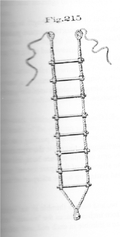
How the Jacob's Ladder was anchored bugged me, so I did some more digging. I found the following statement in Commodore S. B. Luce, U.S. Navy's Text-book of Seamanship. The Equipping and Handling of Vessels Under Sail or Steam, 1891 pg. 61: "...the lower end [of the Jacob's Ladder] setting up to the afterpart of the crosstrees...and hook into eyebolts placed for that purpose." I realize that the date of the book is almost a 100 years later that the commission of the ship, but I think this would not have changed much. So you are right in using the eyebolts. BTY, this same paragraph in the book also gives a verbal description as to how the ladder is fabricated should you want that.
-
The rail cap was next. The practicum used styrene, I used boxwood. The plastic would have been easier, but is nicer. Also according to the plans, the cap is not painted white. Due to the severe curve of the side rail, this was accomplished with two pieces of 1/32” thick boxwood – one cut to the shape of the bow curve and the other was edge bent after soaking in water for a while. The transom was simply a straight piece of wood.


-
Getting pictures that high up of the masts with any detail is just about impossible for the general public. I did some digging in my book library and I found these drawings in Olof A. Eriken's book, Constitution, All Sails up and Flying. I hope they are what you are looking for. The rope ladders it shows are a little different than yours. Jon Rope Ladders.pdf
-
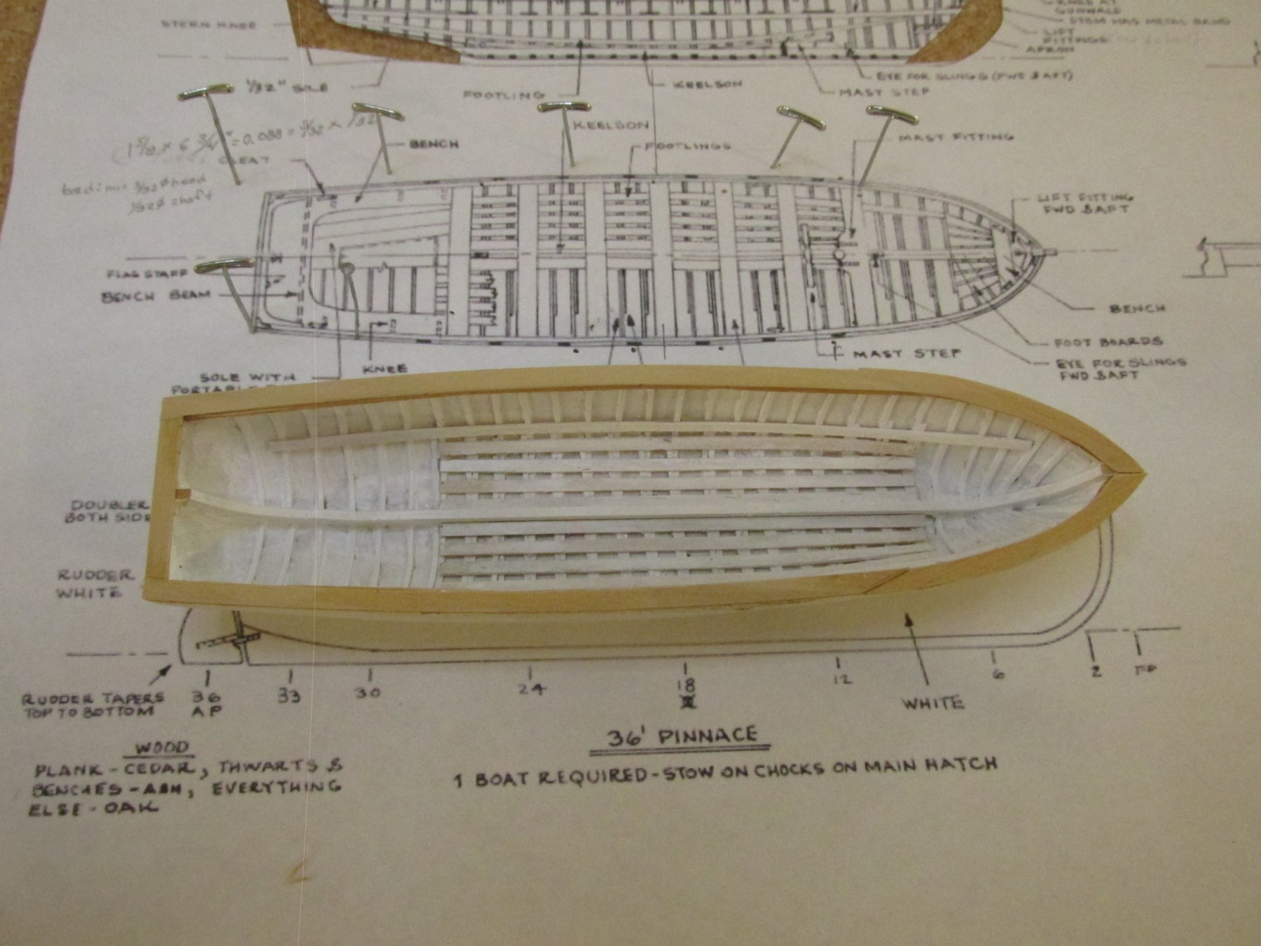
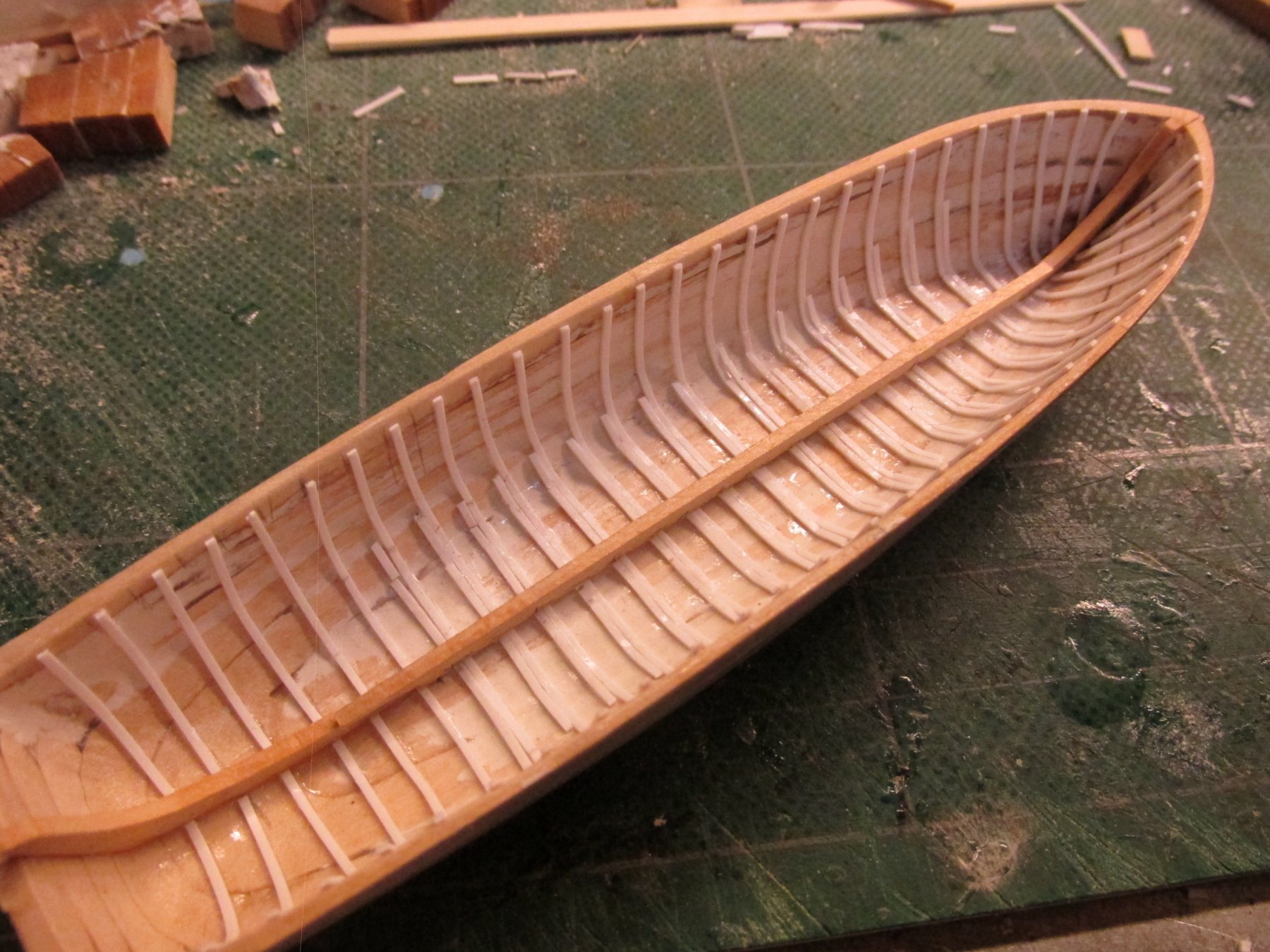
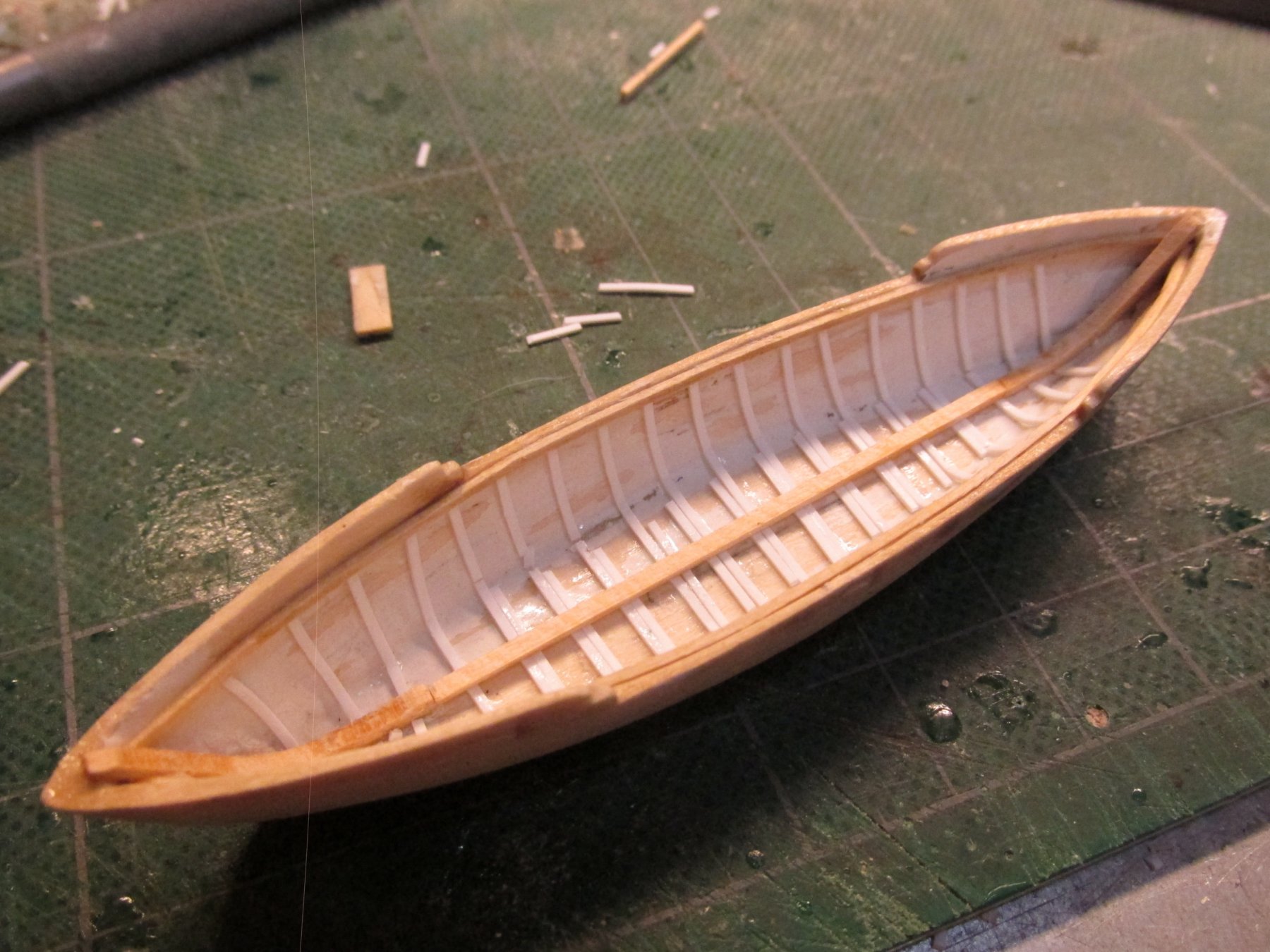
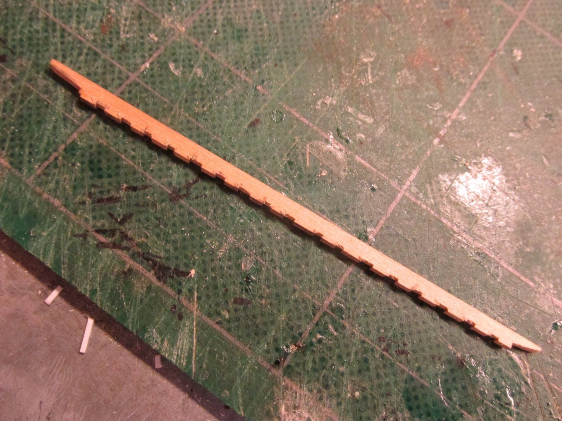
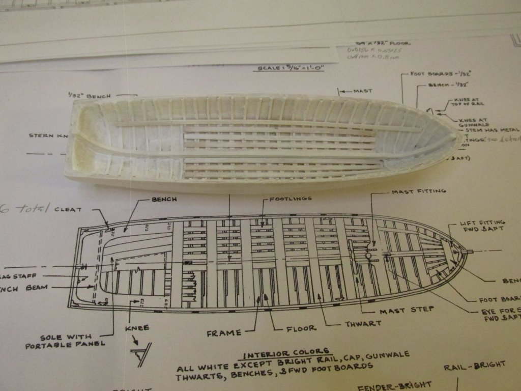
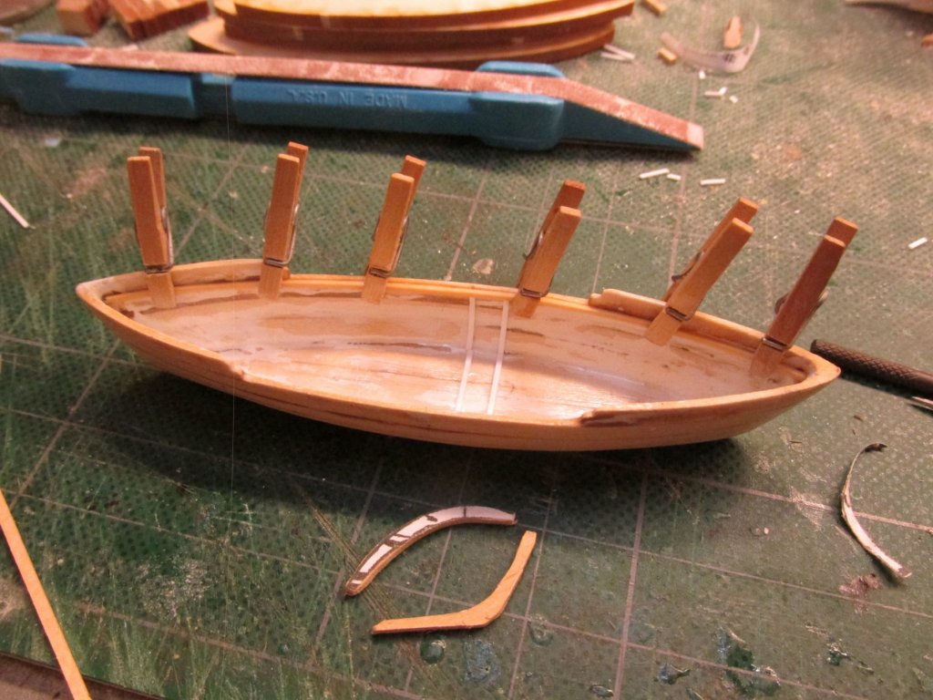
Pinnace Now I will concentrate on one boat at a time. The pinnace is the first. The plans call for 1/64” thick footlings but don’t specify their width. The US Navy plans show these are 5” x 1” or about 1/16” x 1/64” but the kit does not provide 1/64” wood stock. Using the Byrnes saw and some of the kit wood stock (I forget which size I used), that was easily remedied. I painted the cut pieces first and then glued them into place using 1/32” wide spacers.

-
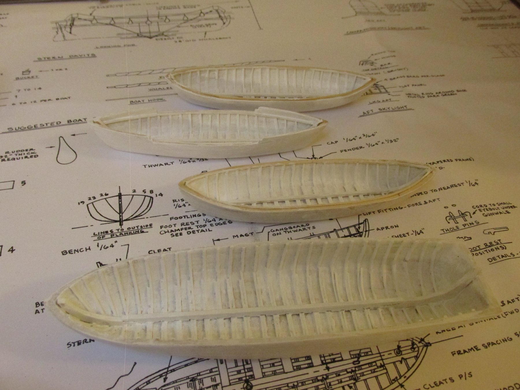
The two whaleboats progressed in the same manner as the gig. At this point, Model Expo came through and my paint package arrive...supposedly again. This time it did not disappear. A coat of white primer was applied to all four boats. I hadn’t realized that I didn’t coat evenly until I saw this photo, but a second coat of primary color paint should take care of that.

-
Are the furlough sails full size sails rolled up? Is that what you mean by "full size sails"? I thought most model builders "cheat" and use just enough material to make furlogh sails look realistic. The problem of course is the scale of the sail material; you just can't get something thin enough, with the right. texture, and translucency to match the scale. Jon
- 481 replies
-
- 2
-

-
- rattlesnake
- model shipways
- (and 1 more)
-
You should be very proud. Now I've got to ask a few questions: I assumed you carved the stars. How did you hold them to do it? The nameplate intrigued me: Did you carve the letters? If not, what did you use? How did you achieve the very thin white border around the nameplate? Jon
- 742 replies
-
- 4
-
-
- constitution
- frigate
- (and 1 more)
-
Do be careful when using the styrene. I've been told they yellow as they age so it's best to paint them.
- 742 replies
-
- 6
-
-
- constitution
- frigate
- (and 1 more)
-
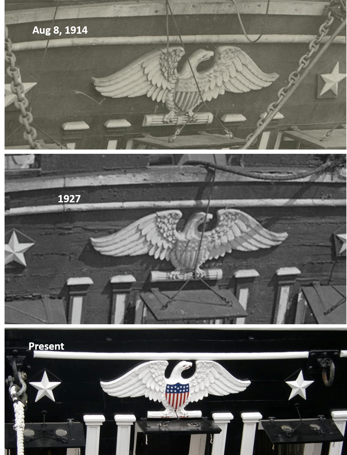
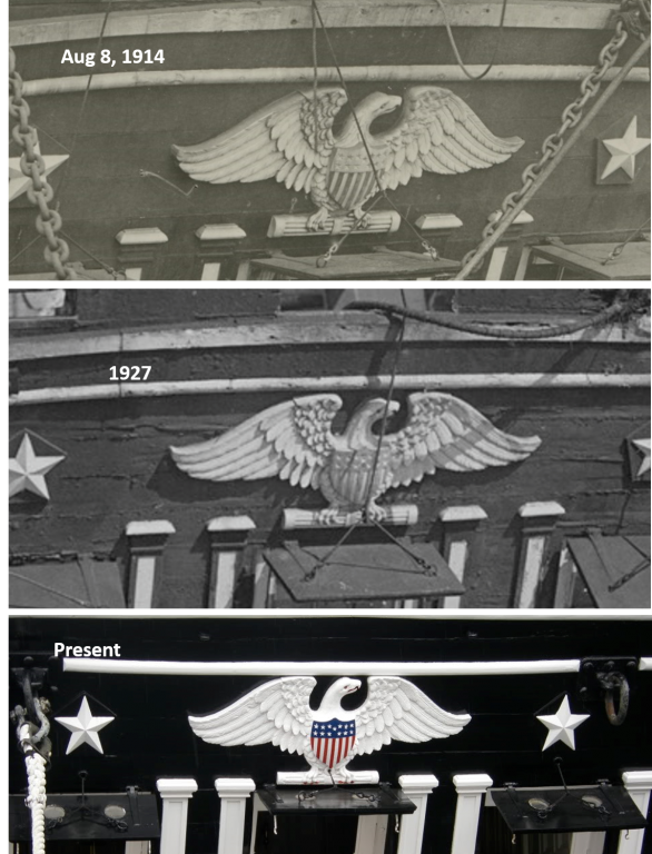
Actual Photos of the eagle in 1914, 1927, and present day. I don't see much difference
- 742 replies
-
- 8
-
-
- constitution
- frigate
- (and 1 more)
-
Those are some nices blades. If only I was doing more carving on a regular bases I could justify those prices. I means they are like peanuts...you just aren't satisfied with only one. 8-)
- 742 replies
-
- 5
-
-
- constitution
- frigate
- (and 1 more)
-
I am curious about the tools you are using for the carving especially the spoon chisel (I think) in the X-acto type handle. Is that part of a set and where did you buy them? Jon
- 742 replies
-
- 5
-
-
- constitution
- frigate
- (and 1 more)
-
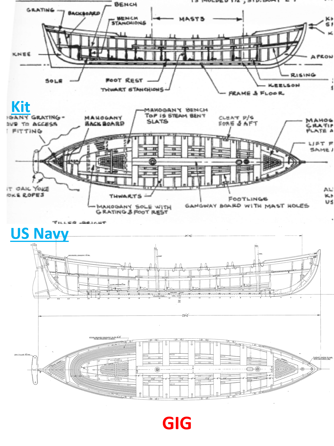
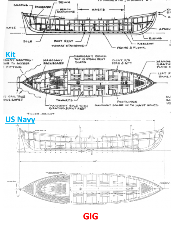
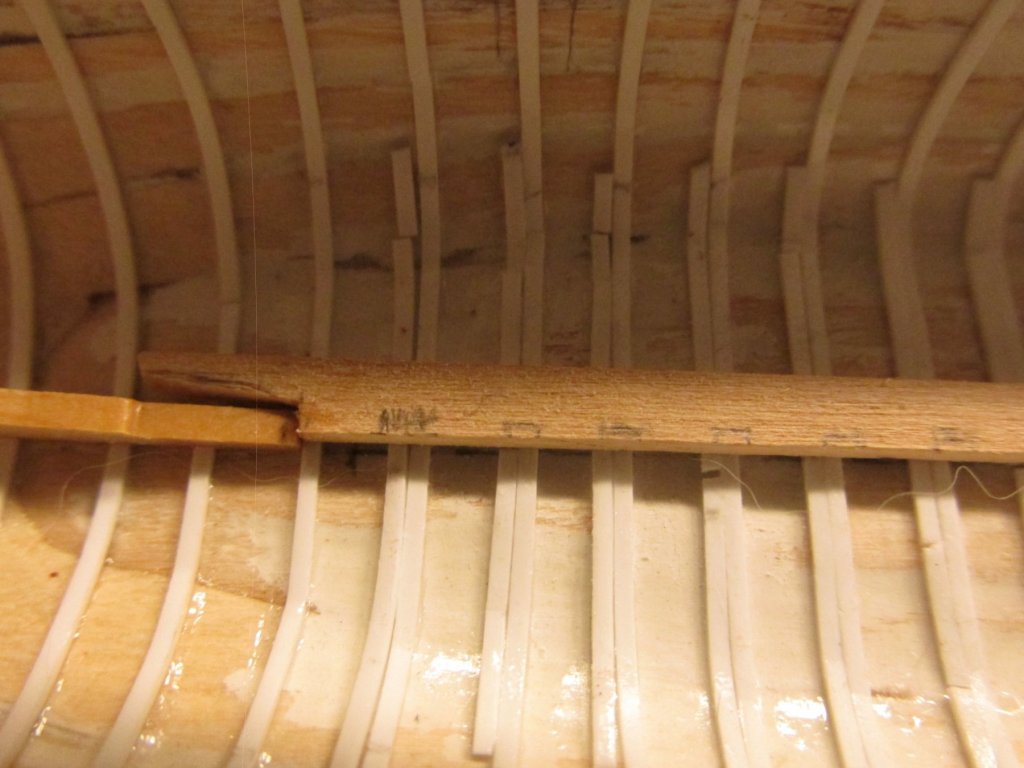
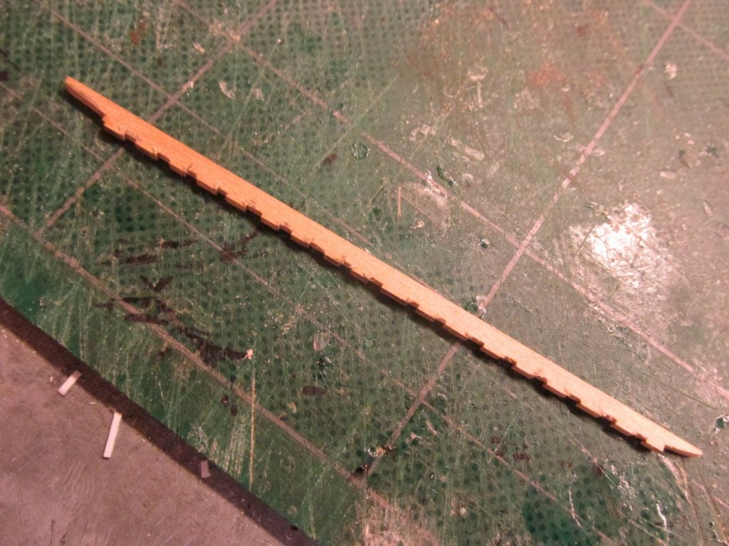
Gig Like the pinnace, the gig kit plans are very accurate as compared to the US Navy’s plans. Hunt’s practicum shows you how to make an acceptable looking model though not necessarily complete or accurate. Some points: The practicum uses one strip of styrene over the ribs to form the gig apron, keelson, and knee. Like the pinnace, I plan to use separate pieces for each and notch the keelson to fit over the ribs as shown on the plans The average observer may not see this detail, but I will know. A lot of the hardware and detail (e.g., lifting rings) were left off due to scale size, visibility, or complexity. The gig backboard and all the gratings were eliminated The gig thwart support stanchions were eliminated The oarlocks were eliminated The “wing” on top of the rudder, and the pintle and gudgeon were eliminated The slats for the stern benches are too fine for this scale and were rightfully replaced by a single sheet of wood. I have ideas about those and the gratings. My intent is to add as much of the detail shown on the plans to the model to the limits of my ability and patience. Here is the gig at the same point as the pinnace with the ribs and flooring supports waiting paint. The only difference is that I added the interior gunwale. So, onto the two whaleboats:

-
At this point I had intended to paint the pinnace before moving on. However due to some unknown circumstance, my order for the USS Constitution paint package which was ordered last month never arrived. Both Model Expo and the US Post Office have recorded the package as being delivered within a week of my order, but that was a month ago, and I never got them. Model Expo has promised to resend another shipment. Thus, I have moved on to the gig.

-
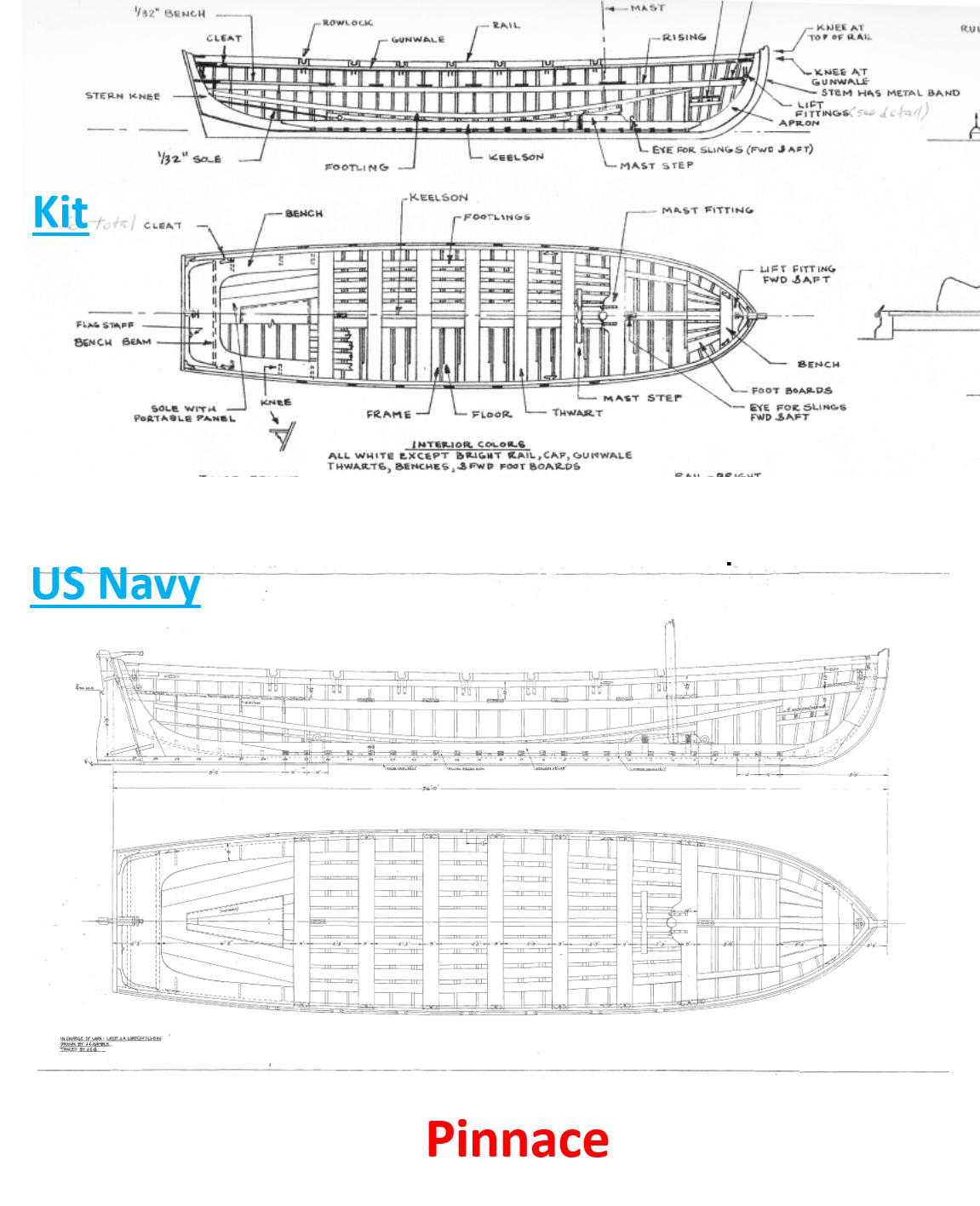
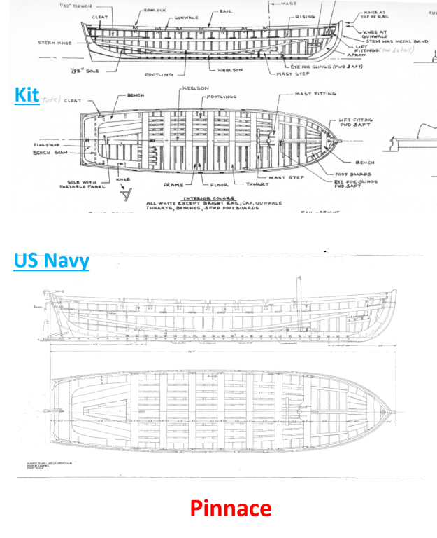
General Thoughts Having the actual plans from the US Navy for the ships boats is wonderful and luxurious. Usually when making a model I must rely totally on the kit to provide me with the all the details because I normally don’t have the real thing to look at. My Rattlesnake is an example. With the actual plans, I can see how the kit’s plans adjusted for scale and ease of building. With the build logs, I can also see what other builders added, modified, or eliminated.
-
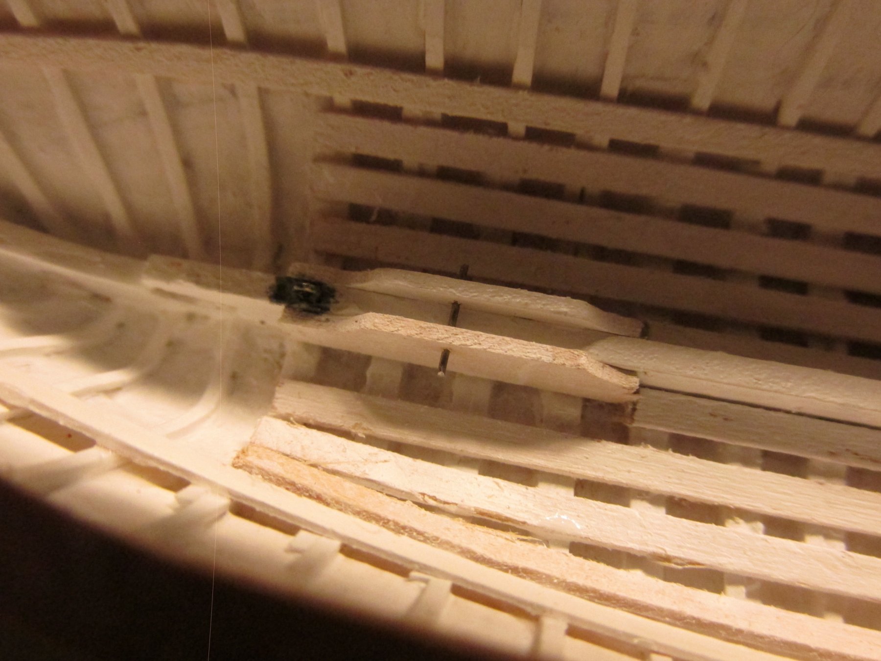
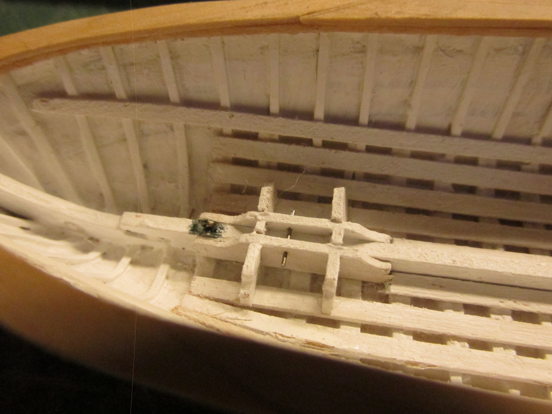
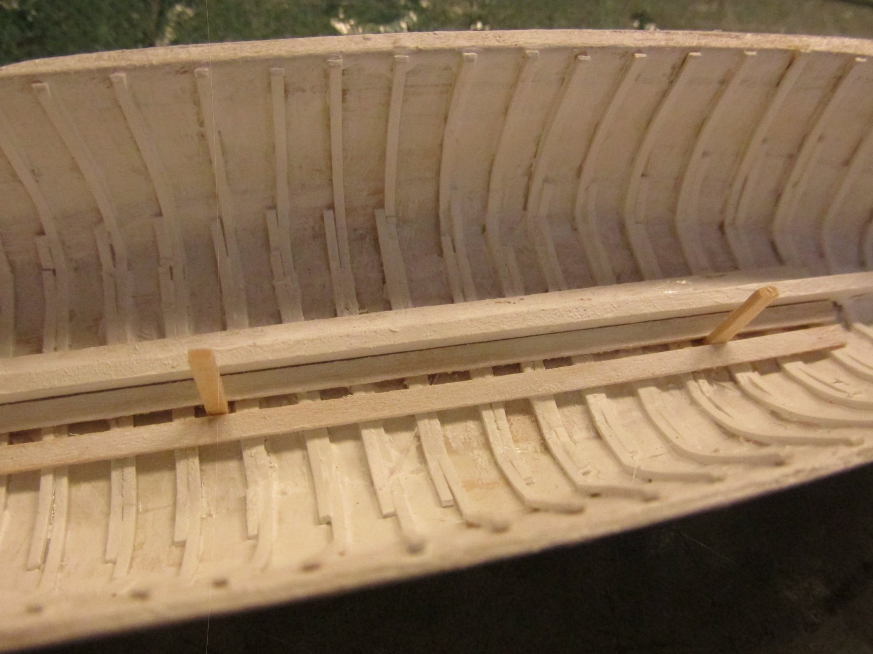
In my last post, I had forgotten that I had taken some shots of the notched keelson (they were still in the camera) so here they are. BTY, you can see where the styrene broke. Luckily, all of this will be under a couple of coats of paint and nearly hidden once the boats are completed. So unless you know they are there and have very good eyesight with proper lighting, it will be hidden.
-
Not only do I not know when that plan was drawn, I don't know where I originally found. I thought I got from the CD the Constitution museum was selling, but it's not on there or on the 2001 version of the CD. At one time, the US Navy had a lot of their plans on their website, but no more. I must have gotten it there before they took down their archive pages. The only clue I have is the name G F Campbell written on the very bottom right hand corner of the document. The only G.F. Campbell I could find was the author of "China Tea Clipper" and "The Neophyte Shipmodeller`s Jackstay." Sorry I couldn't be more helpful Jon
-
From the US Constitution CD of navy plans, see if this file helps on those bukwarks 10068001 - Gun Deck & Inside of Bulwarkse.pdf
-
As always, nice and clean. Jon