


JSGerson
-
Posts
2,151 -
Joined
-
Last visited
Content Type
Profiles
Forums
Gallery
Events
Posts posted by JSGerson
-
-
Mast Wedges
At this point it was time to construct the main deck mast wedge under the foredeck like was done for the main deck under the quarterdeck. But an unforeseen complication arose; per the instructions of the practicum.
In Chapter, 8, section 8.1.3, Page 24, Mr. Hunt describes the creation of the mizzen mast wedge for the parquet floor on the Main deck. The stock material was 1/16" x 1/4" swiss pear which was based on the 3/16" dia of the mast:+ 1/16" + 1/16" (thickness of ring on either side of mast) = ~1/4".
The wood package contained 1/16" x 1/4" swiss pear. So far so good.
In section 8.2.4, Page 108, the practicum addressed the foremast wedge under the forecastle. It stated: "And like the mizzen mast, there is a small mast wedge made of swiss pear on the main deck...The mast wedge was made the same way I described earlier."
The foremast is 1/4" in diameter. To make the wedge I would need a stock piece of 1/16" swiss pear of at least 3/8" square: 1/4" + 1/16" + 1/16" = 3/8".
There are a total of 3 wedges of this size, two on the main deck and one the forecastle.
The wood package had nothing in swiss pear of this width in any thickness. At this point my only alternative was to create them in boxwood and then stain them as best I could.
I immediately contacted Jeff Hayes of HobbyMills and started the email with “You wouldn't of seen this one coming.” Mr. Hayes was again very gracious:
“I guess that Bob just used some pear that he had lying around and forgot to add it to his list. If you need a piece of 1/16 sheet stock, just let me know. As an alternative, how about gluing two layers of the 3/64 x 5/8 together to make them?”
Looking at my supply of 3/64 x 5/8” swiss pear, I realized that that didn’t have too much left and didn’t know if I would need it later so I reluctantly went with his first option. Letting Jeff know I felt guilty about “nickel and dimeing” him he asked and I agreed immediately to at least pay for the postage. Within a couple of days I received a piece 1/16” swiss pear 1 1/8” x 24”, more than sufficient to create the wedges and anything else I might need. Thanks Jeff.
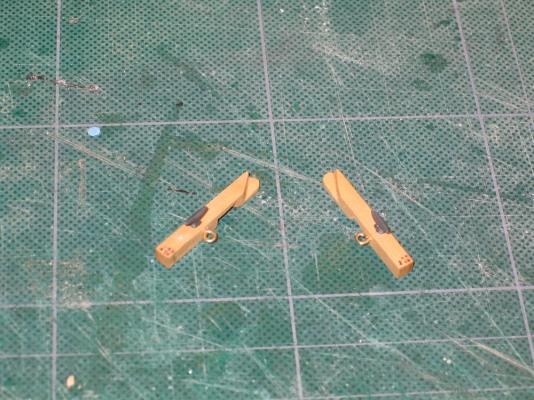
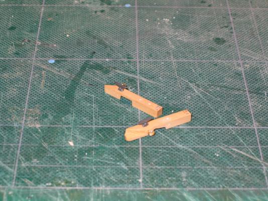
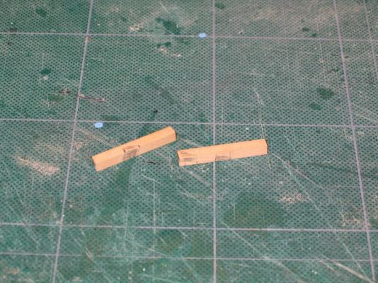
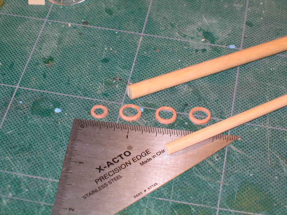
Well if I was going to make one wedge, I might as well make all of the remaining wedges. Here you can see the progression in mast wedge construction.
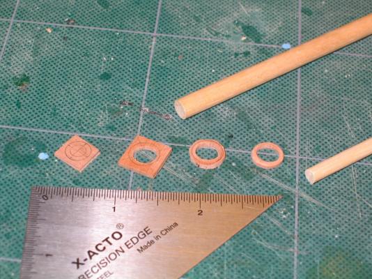

-
To ensure proper fit, dry fitting with the dowel was done numerous times.
-
Forecastle Deck Planking – initial
With the catheads installed, it was time to start the forecastle deck planking. Just like the quarterdeck, 1/32” x 3/32” holly was used. Starting from the center the first plank was set in place. The practicum would have me lay out all the planks and later on drill out the foremast hole. I elected to create the foremast hole earlier. As soon as I had glued down the second plank, a notch mas make in the center plank to indicate where the foremast was to pass through the deck. By the time I had five planks down, I commenced to complete the hole. I wanted the five planks glued in solid so that when the hole was expanded to fit the dowel that would become the mast, there would be enough strength to resist drilling and filing. The mast has a rake to it and the deck hole butts right up to the support beam below so everything had to line up perfectly.
-
Thanks. I'm not ready to start rigging yet so I'll wait for a sale that applies to the plans. $50 is $50!
-
"I received the ModelShipways Rattlesnake plans as an additional reference (gee, why am I putting in all this extra time and $$ on this.............I might be rigging by now...)"
I am contemplating getting a set of the ModelShipway Rattlesnake plans myself. I have not seen what the plans look like. Is there anything in them that it is worth the $50?
-
I am waiting with anticipation to see how you install these fixed blocks onto your model. As you may know I'm following Mr. Hunt's practicum and his method for installing these is totally different but I didn't really like his results. Of course I'm no expert either in historical ships or model making and I would have followed his method blindly, but so far I like your method. I can't wait to see what you do next.
-
Very neat job. For hinges I just used black paper and for the door knobs, the head of some finishing brads I had from an old kit of some sort.
-
Yeah, they now have a coat of poly-wipe on them where as before they didn't. Right after I plank the quarterdeck, I get to go the rail process one more time when I put in the hand rails. That should be as much fun fun!!
-
I then went and installed the catheads

- themadchemist and 4whelr
-
 2
2
-
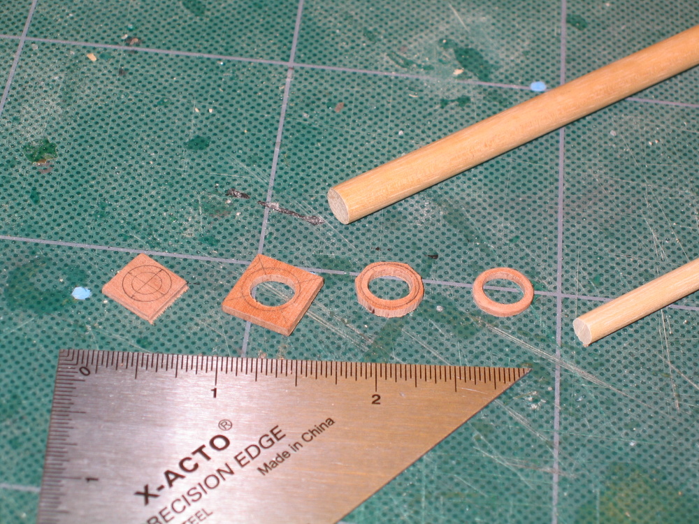
I went a step further than the practicum and added the cleats and rings. It seemed a whole lot easier to do that now before installation on the model than latter when Mr. Hunt did his.
-
Based on those marks, the areas to be cut out were blackened so as to make it clear where to cut. Using the fine tooth hand saw from my miter box and micro chisels, the appropriate areas were removed and fitted. This took me two attempts with the second being adequate, not perfect.
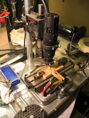
At the tip of the cathead are six holes for rigging the anchors. The kit shows only four. Knowing that I had to drill through 5/32” six times precisely I used my Dremel drill press jig. Now I am blind as a bat and have to work with an eye loupe attached to my tri-focal glasses. Trying to get my head close enough to the drill press work area so that my lenses would focus, was a challenge. I would have sworn I was right on my marks but the results left something to be desired. If I had a true drill press, I don’t think I would have had the same results. The drill drifted because the jig wasn't as rigid enough so that the holes are not exact where they should be. The imperfections are there if you look for them.
-
The Davit Catheads
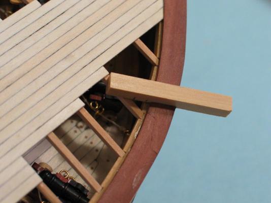
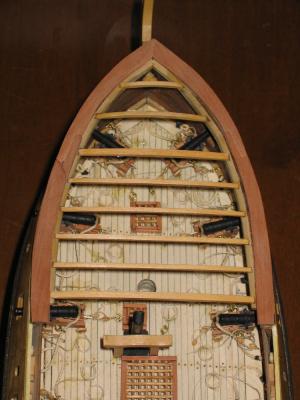
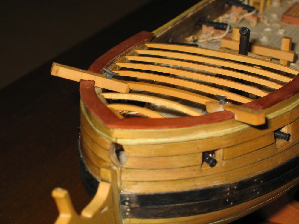
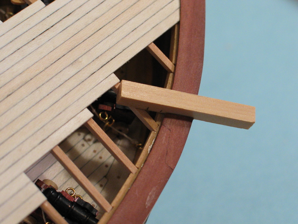
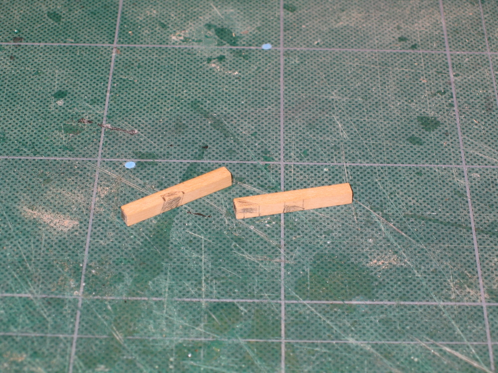
This turned out to be a race in patience. Would I run out of patience before the pieces were completed? It was almost like weaving wooden sticks. The catheads start under the forecastle beams and end above and resting on the bow rail with few perpendicular cuts. Starting off with a piece of 5/32” square boxwood stock, two pieces are cut 1¼” in length. Laying each one on the appropriate bow rail and the third beam back from the tip of the bow, marks were made to indicate were these piece would cross either over or under structural points. The third beam by the way is wider than the other beams. This is illustrated in the practicum. You will notice that Mr. Hunt has already planked the forecastle.
-
Just a couple of quick questions, who makes serving machines and where did you get yours?
-
Thanks for the undeserved compliment.
Until you mentioned it, I wasn't really aware of the boomkins. As a matter of fact I had to look up the term to see what you were talking about. And you are right. Bob Hunt does not address them, yet there they are in the Mamolti and Han's plans. I have on my computer 42 folders of rattlesnake models made by different people. Some of those folders have just the final model with a few images and to others with the complete build. I checked every image that showed enough detail in the bow to see how the boomkins were constructed. Surprisingly not all the models had them and those that did, I couldn't see well enough to see how it was done. The plans don't show enough detail either. I don't know what the MS plans show because I don't have them...yet. I'm waiting for a Model Expo sale that will cut down the $50 price tag. I'll have to do some more research in the few books that I have. From what I can see, it looks like I have some time yet because it appears that they should be constructed somewhere in Chapter 9 of the practicum had they been addressed. I haven't finished Chapter 8.
Thanks for the heads up.
-
Practicum Deviations
At this point the Practicum would have me plank the quarterdeck. This won’t happen yet.
- I've opted to skip this step and build the two davits first while the deck beams are still exposed. Then I’ll go back and plank the deck.
- I was surprised that the Practicum did not address the bowsprit at this point. Once the quarterdeck is planked, you cannot see the deck below where the bowsprit is attached. If any adjustments have to be made during the construction of the bowsprit to make sure it mates properly with the ship’s deck, this would be your last opportunity to do so. The Practicum does not address the bowsprit until Chapter 1 of the Rigging Supplement which follows the final hull construction Chapter 9. I went ahead and constructed the basic bowsprit mast without any of its accouterments to make sure it at least fit properly. For sake of continuity this will be discussed when I actually start assembling the bowsprit.
-
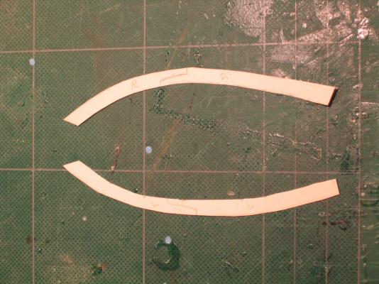
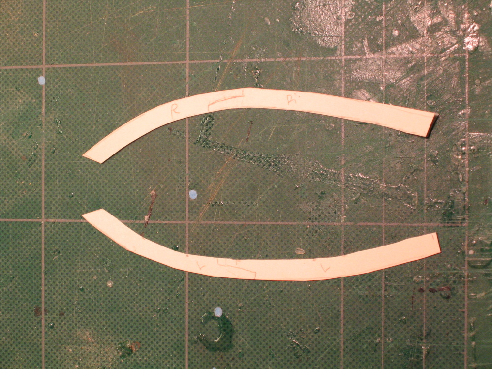
The pieces were then cutout using my old Dremel scroll saw and finally glued into place. This was not as easy as it appeared. I had a devil of a time getting all the pieces to fit right. I even had to make two of template pieces over again. I got it to work and accepted it, but still not really truly satisfied. If you look closely, where the left scarf joint broke during the cutting process. I got it mended OK, but couldn’t remove all of the glue stains.
-
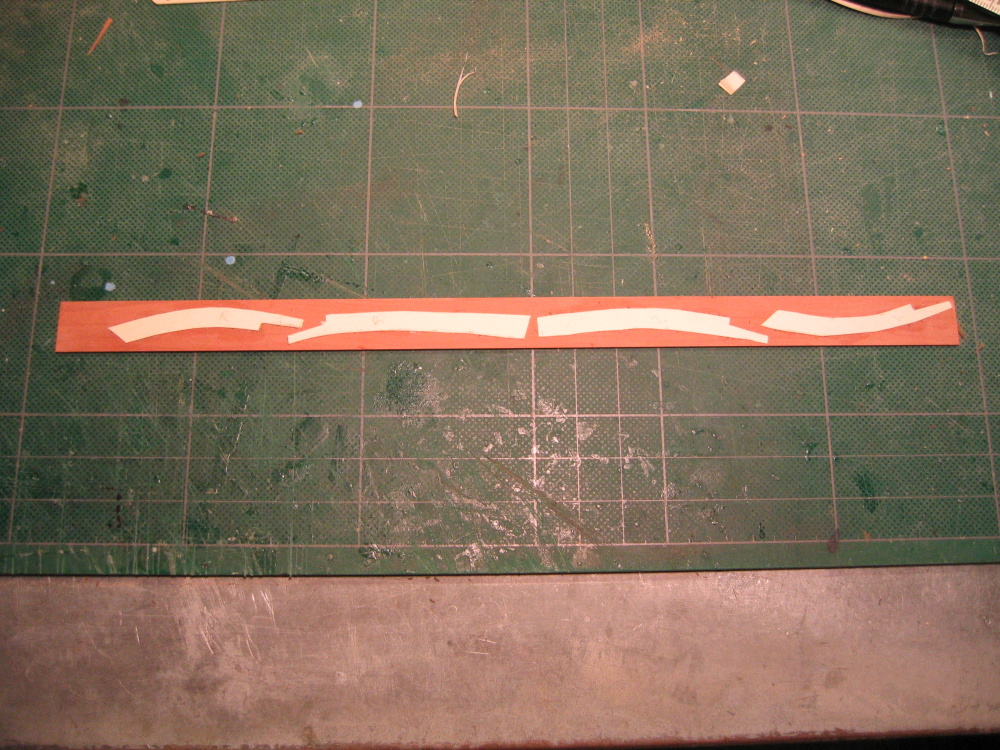
Then because of the severe curve of the bow, each template was divided into two with a scarf joint just like the actual boat. The templates were then rubber cemented to 3/64” x 5/8” swiss pear stock

-
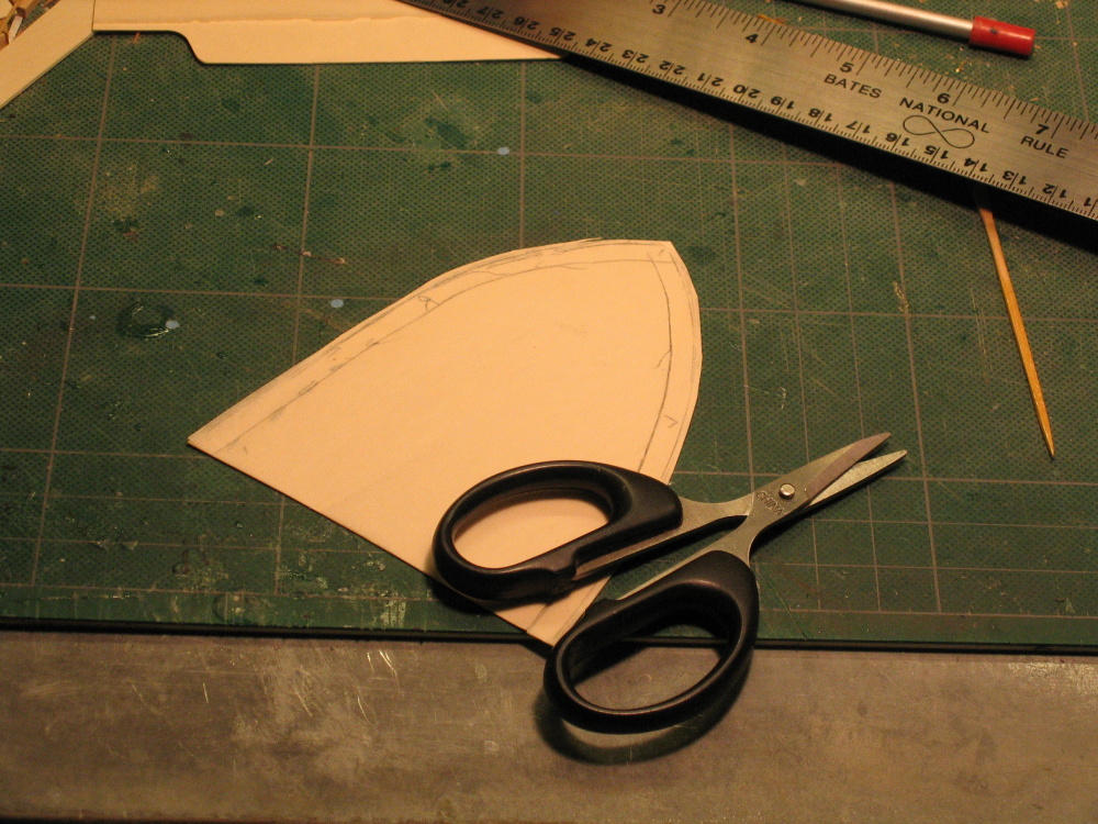
Forecastle Rails
This constructed just like the quarterdeck rails. A tracing is made of the outer edge of the hull. Because the outside edge of the rail overhangs the hull by 1/32” the card stock was cutout with the extra thickness on the outside edge. The inside edge is measured about ¼” inside as a parallel line to make the initial templates. The tracing was then rubber cemented to card stock and the excess stock was trimmed and fitted to the bow.


-
Thanks Russ & Martin. I'll use what came with the kit and buy any additional ones if the need arises.
-
Luckily I am not so far along as you are in building Hunt's kitbash, so I can follow in someone else's footsteps. Because your log starts at the rigging stage and therefore does not describe the hull construction, I am curious as to whether or not you used the metal belay pins that came with the Mamoli kit or opted to make your own or buy wooden ones. If you did use the kit's pins, how did you handle the coloring of them (stain, paint, etc.)? I'd be real curious as how you made them if you did that. If you bought them, from whom, what size did you purchase, and were you satisfied with the product?
Even though the construction of the pin rails were addressed in Chapter 8 of his practicum, he addresses drilling the pin holes and installing the belay pins in Chapter 9. I've already installed the quarterdeck rail without the holes which I think is wrong and plan to drill the holes before the foredeck rail is assembled, hence my questions.
Thanks
-
Now why didn't I think of that, it's so simple!
-
Shhh! If I don't tell the average viewer of the model, they won't know!
-
As for those ladders - ai yi yi, the headache they gave me!!! But I got an enormous bit of help from Alan Yedlinsky, who wrote one of the books for Seawatch -- he sent me the info on building a jig that lines up the grooves in the side parts of the stairs (can't remember what they're called), and bing bang boom, it all worked fabulously.
Any chance you could pass on to the rest of us those plans for the ladder jig? I'm sure a lot of other people are or will have the same problems too.
To be fair, I couldn't have done as much as I did without Bob's instructions. They may not be perfect but they are quite detailed for the most part and a whole lot easier to follow than the Mamoli plans. Also, I've have no complaint with HobbyMill's service or products. In fact Jeff Hayes of HobbyMills bent over backwards to make things right.
But you are right about the rigging. If you look at the actual model that Bob Hunt made, it has no masts or rigging. He did mention somewhere in the Practicum that he was building four model at once while writing the Rattlesnake practicum, so OK, he cut some corners and I'll cut him a little slack. The rigging is a chapter and a quarter away so I just might look into your foot steps to purchase the MS plans.
-
Well I might as well throw my two cents in. I guess it would depend on what time frame the model represents. As you well know, what it looks like today, is not what it looked like in the thirty's never mind what it looked like in 1812. Today the actual ship has a red stripe, in the past it didn't. If the rest of the model represents the ship as it looks today then by all means add the stripe. But that's just me.
I asked my nephew this question about the copper tape. He works for a company in Japan (he speaks very fluent Japanese) that deals with adhesives and coatings, matching buyers with sellers of these various products. In other words they match the problem with a solution. He does all their technical translations into English as well as maintain their website. He is NOT a model builder however. He responded:
Good question. I've actually never come across copper tape before, but I'll look into it. It's something we don't cover specifically, and if I haven't come across it, that probably means we've never covered it. That said, I can tell you all kinds of things you never knew (or wanted to know) about copper tape.You are correct in assuming that no tape lasts forever. Under specific conditions (mostly sealed conditions) it can last years, even decades. They use all sorts of tapes in construction now, but that is usually for temporarily holding things together until something more permanent is used (screws, etc.). But in a sealed environment, such as that inside an aluminum window frame, it will last as long as your house is standing. In fact, those tapes are often used for waterproofing and not as a structural element, so must be virtually immune to water and moisture.But the big problem with adhesive tapes is two fold. The first is that most are pressure-sensitive, which means they don't even try to be permanent. The second is that it really depends on what you are taping (the adherent). I am assuming you will be working with wood, and very porous wood at that. This means that oxygen will reach the adhesive layer relatively easily, and quickly. This will oxidize the adhesive (not to mention the copper itself), and cause it to become gooey or dry out, depending on the adhesive agent. The difficulty is in finding a copper tape that uses the right adhesive agent for the adherent. Most stick to wood pretty well because wood is rough, but before applying the tape, make sure there is as little dust as possible. This will increase the life of the tape.You could also put a transparent sealant over the tape to increase it's life. I assume you would add a sealant to the ship anyway, so you would want to do this after applying the tape (granted, the solvent in the sealant could dissolve the adhesive, just as the solvent in the adhesive could dissolve the paint it is on and cause delamination). In the Tiffany lamps, the solder is basically used to seal the tape so that oxygen does not reach the adhesive agent. Copper tape is used because copper is heat resistant and conductive and can thus withstand the soldering temperature and bond well with the solder itself. I doubt you could solder copper tape on a wood surface, though. Not that you would want to anyway for the application you are considering.From my understanding of how adhesive tape works and knowing that you would not be working in a nice environmentally controlled area with pressure gradients to whisk away dust as you worked, I would find an alternative. Tape is what is usually called a PSA (pressure sensitive adhesive) and is thus always in a moist state. So I would use a true adhesive that dries completely and copper foil strips. I know that would be more difficult, but if you want it to last years, or decades, to me that seems like the better option.I'll see if I can find anything on existing tapes in terms of durability, but I have a feeling that copper tape is not designed to be applied to wood or organic surfaces (paint, etc), so I would recommend against it.I don't know if I have opened a can of worms, muddied the waters, and befuddled everyone. Let's see if he can come up with a more definitive answer.I would hate to have to glue individual strips with CA glue to get long lasting results.


Rattlesnake by JSGerson - FINISHED - Mamoli - 1:64 - Using Robert Hunt’s practicum
in - Kit build logs for subjects built from 1751 - 1800
Posted · Edited by JSGerson
The wedge was installed under the foredeck by placing it on the dowel after it had passed through the foredeck. The dowel was then positioned and inserted into the main deck mast hole and the wedge was then pressed to the deck. Once the Weld Bond glue had taken hold (about three minutes), the dowel was removed. The remaining wedges were set aside for later. The planking continued.