


JSGerson
-
Posts
2,480 -
Joined
-
Last visited
Content Type
Profiles
Forums
Gallery
Events
Posts posted by JSGerson
-
-
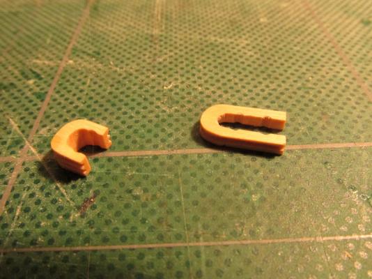
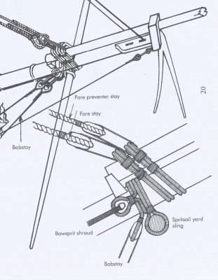
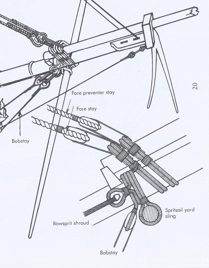
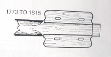
A second collar had to be constructed similar to the first for the fore preventer stay. This is the line the crow’s feet attach to and therefore not shown on the Mamoli or Model Shipways plans. Unfortunately this collar is different than what is shown in Antscherl’s book – it is much longer and appears narrower in Hahn’s plans. I took my best shot and winged it.
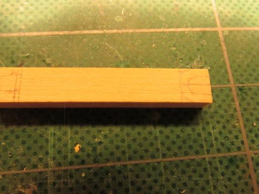
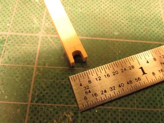
Again the collar had to be the same width as before but almost twice as long. In this case I followed Hahn’s plan and made it with one side groove. It was constructed about ½” long from ¼” x 5/64”

-
At this point a choice had to be made. Both the Mamoli and ModelShip plans were in agreement with each other but not with Harold Hahn’s plan. Mr. Hahn showed crow’s feet rigging and since I had decided early on to follow the Hahn plans when possible, the crow’s feet were in which affect some of the rigging scheme. Some other details like whether to use deadeyes or hearts on the bowsprit also came into play. From my readings and looking at the various models, it was apparent that there really wasn’t a rigid standard rigging scheme. A lot of the details were at the discretion of the captain and those could change during the course of one cruise. Since I’m the captain of this particular ship I can’t be wrong…mostly…well maybe.
I made two more hearts similar to the bobstay to wrap around the bowsprit for the two bowsprit shrouds
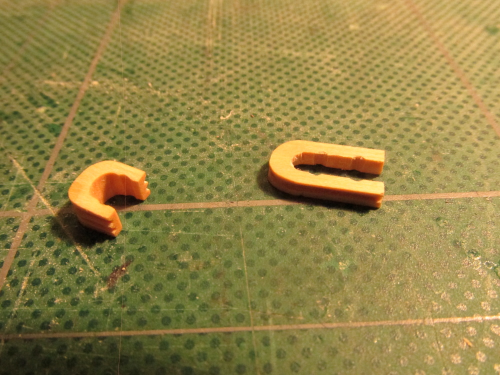
The forestay has an open heart. Following the guidance of David Antscherl’s The Fully Framed Model, Rigging a Sixth Rate Sloop of 1767 – 1780, Volume IV [FFM], the open heart or the forestay collar as Antscherl calls it. “This is a 13” open heart with a 5” four-strand cabled collar that is doubled,” requires two grooves along the side which will be apparent below. This does not follow Hahn’s plans or at least I think it doesn’t because the only view is from the side and shows one groove. But as I stated before, I’m the captain. The idea of the heart is to allow the jib boom to slide between the forestay lines. Based on that, the 3/16” long heart was made from a piece of ¼” x 1/8” boxwood. The grooves were initially cut with the Byrnes saw and the filed to a semi-circular cross-section.
- Martin W and CaptainSteve
-
 2
2
-
Glad to have you posting again. You and I are at about the same point in our Rattlesnake builds abet mine is 1:64 scale. Now I'll have you to lead the way once more. I await with high anticipation!
-
If you can't get anymore cannons of the type you want/need, you can always close the gun ports under the fore and aft decks to show what the ship looks like with them closed. Because your decks will be completed (I assume, unlike mine) the viewer will not be able to see below decks very well. I will be too dark and cluttered. I have seen a number of models done this way.
-
When rigging the guns on my Rattlesnake, I was ignorant of making pretty coils of rope. When some commented to me about this I started to look into how to make them. Usually the answer I got was to wrap the rope between two piece of clear plastic disks pieced by a pin or nail. However I did receive this one comment as follows:
"I wouldn't bother trying to model those coils like that. They are purely decorative and no sailing ship would have them unless they had visitors coming aboard; Dignitaries, VIPs etc. They tend to keep moisture and rot the deck beneath them if they are left there. They are "yachty" and most sailors wouldn't have them on their boats. I wouldn't."
So I didn't change rope coils and saved myself a lot of work in attempting to do them over. Mine look more like a working coil of piled rope. The choice is yours.
-
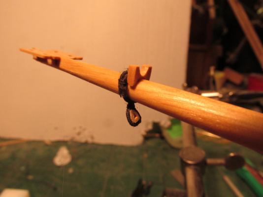
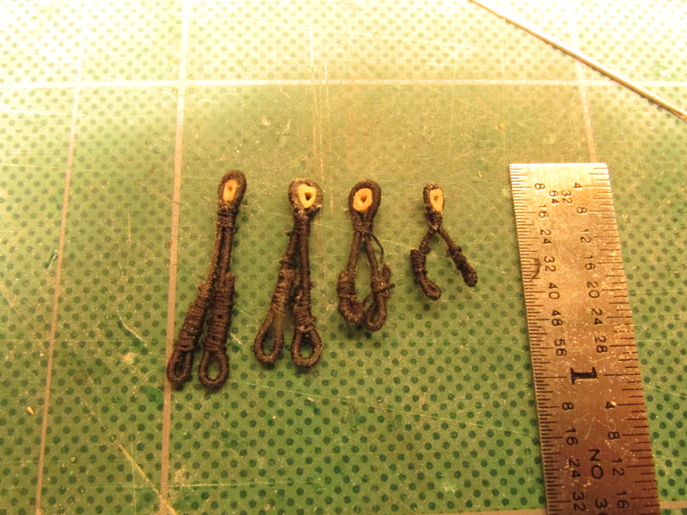
Well third time, no wait forth time, no that’s not right, it’s four and a half times is the charm. I made the seized component a third time but this time I reduced the diameter of the rope from 0.8mm to 0.4mm. Remember I initially stated I needed 0.6mm. With the added seizing and the very tight quarters it was to me placed in, I figured I could get away with it, plus the seizing itself added to the diameter of the line. I also tried to shorten the seizing required for the loops and heart.
Once more I went to place it on the bowsprit and amazingly it was still too long. This time I undid the seizing on one loop and shorten where the loop started. The loop was re-seized and low and behold it fit!

- MEDDO, Martin W, CaptainSteve and 2 others
-
5
-
If I do say so myself, much better!
-
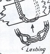
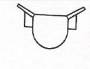
The component was then folded over in the middle and a heart was glued and then seized at the fold. The idea was that this would wrap around the bowsprit with the heart hanging down as shown in the bowsprit diagram. The two loops would be lashed together at the top as shown to the diagram below. As it turned out both components were too long – the loops over lapped. So I made a third one and guess what? It’s still too long! The good news is I’m getter better at making these things and have noticed that I had too much seizing at the loops and heart. Four hearts down, 6 left. Well back at again.
Note: the two diagrams came from: Rigging Period Ship Models by Lennarth Petersson

- WackoWolf, Martin W and CaptainSteve
-
3
-
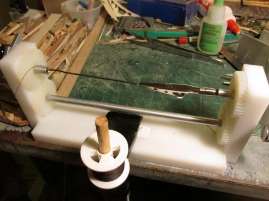
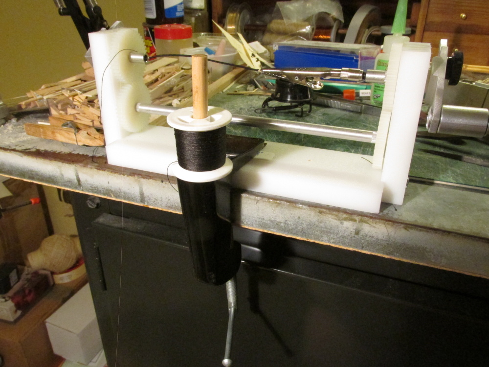
In case anyone was wondering, my seizing machine came from shipahoymodels.com. The clamp I using to hold it in place is a desk lamp clamp and where the lamp would pivot, I stuck a piece of dowel to hold the spool of thread. It worked quite well.
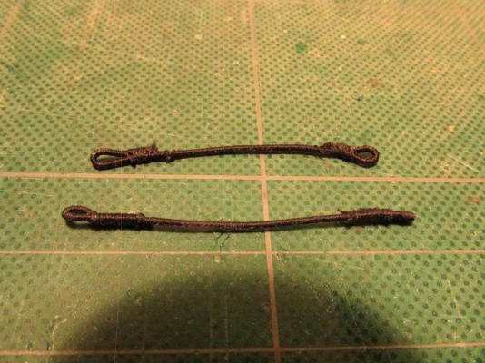
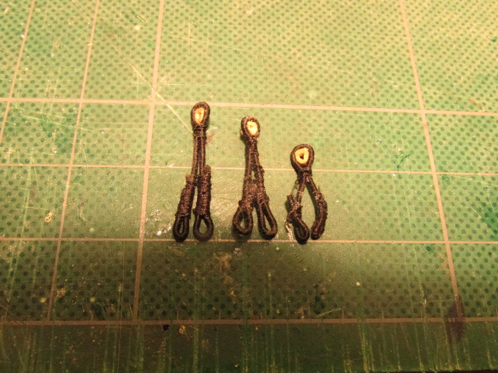
Once the line was seized, it was removed and one end was folded over to create a loop and it was seized again. It was then repeated for the other side. As you can see, two components were made, one smaller than the other. I wasn't sure of the exact length needed.
-
Next I had to make the stropping that goes around the heart and the bowsprit, which required that I seize the full length of line. The actual line is 1 5/8” f scale or 0.6 mm. The kit provided beige (no black) 0.25 mm, 0.4 mm, 0.8 mm, and 1.2 mm line sizes. I decided to use the 0.8 mm line with black 0.1 mm sewing thread for the seizing. The black thread would completely cover the beige color. Standing rigging was waterproofed with a tar covering and thus black.
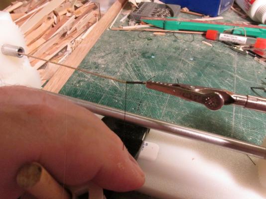
Using my never before used seizing machine, I proceeded to seize about 3” of line so I would have plenty to work with. First the beige 0.8 mm line was pierced through with the black thread to mechanically secure the thread. The seizing proceeded by cranking the handle of the machine and feeding the black thread through my fingers to keep the line taught. It worked flawlessly.

- Martin W and CaptainSteve
-
2
-
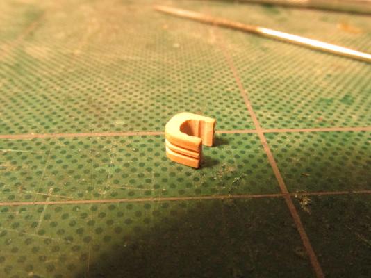
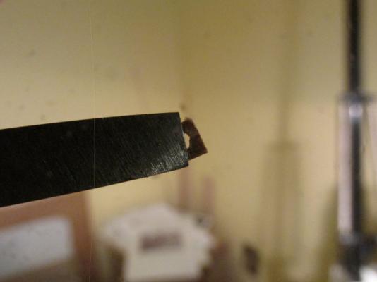
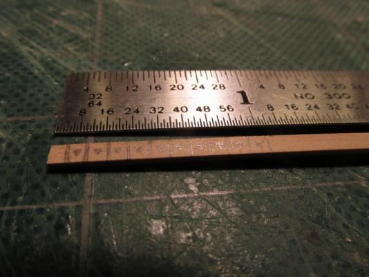
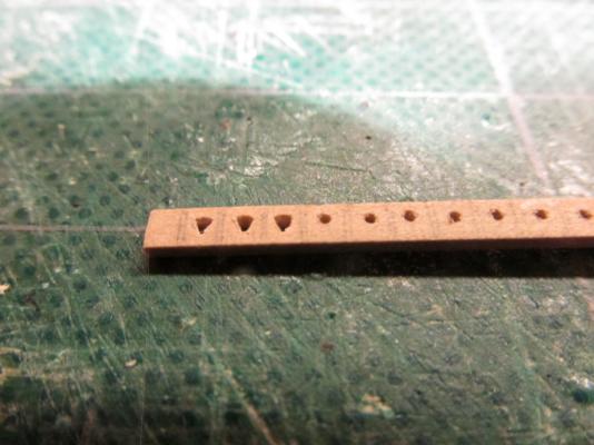
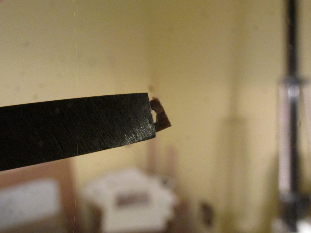
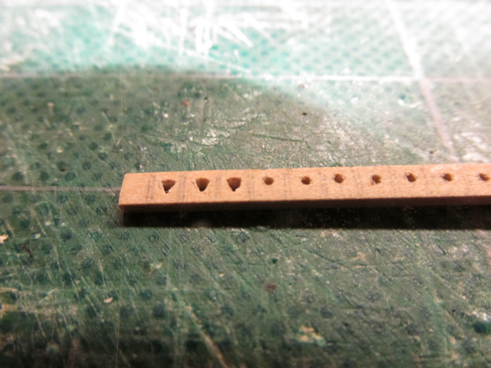
Once the holes were completed, the individual hearts were cut off from the stock and held with needle nose pliers in order to file the sides to the proper shape. Then, with one of the edges of the triangular needle file, a groove for the rope line was cut around the sides of the heart just like you find on blocks. I only lost one heart when it crumpled in my hands. I filed one of the edges too close to the internal hole. One down, nine hearts left.
- Martin W and CaptainSteve
-
2
-
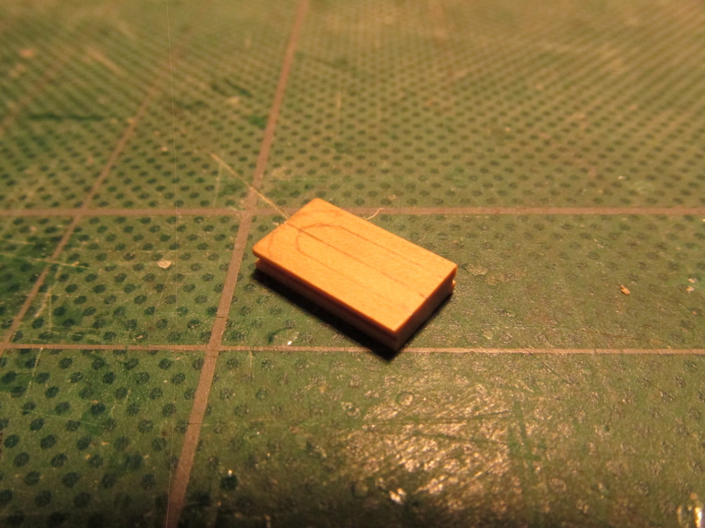
Following my plan to attach everything I can to the mast and yards before I install them onto the model, I decided to try my hand at the parts of the bobstay that are attached to the bowsprit. The first thing I needed was a 6” closed heart. Unfortunately none came with the kit and I couldn’t find any on the internet in scale (1:64). I had to make it. Choosing a piece of 1/32” x 3/32” boxwood stock, I sketched out 10 hearts because I really don’t know how many I’ll need in the course of the build. A hole was drilled and then filed into a triangular hole with triangular needle files.
-
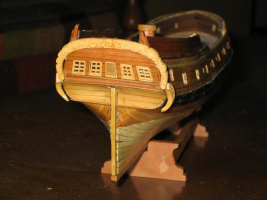
I purchased the MS plans as well as Harold Hahn's plans, and of course I have the Mamoli plans. Each one shows certain details better (or different) than the others. I also downloaded the MS instructions. You never have too much information (unless it's all contradictory). The MS plans show the gap very clearly but does not depict the planking of the transom. Think about how the shipwrights of the day would have made the stern. They didn't have large sheets of plywood so they had to have planked it.
I'm following a Practicum by Robert Hunt (LauckStreetShipyard.com). He provides a detailed set of instructions to either build the kit straight out of the box or kitbash it. Although the Practicum is based on the Mamoli kit, he claims it should work for the MS kit as well. Now the Practicum is not perfect and even less so beginning in the last chapter before the rigging starts, but I couldn't have done what I did with out it. The Mamoli instructions are printed directly on the plans in multiple languages and are hard to read especially with my eyesight. So I read the books, look at other people logs, ask questions, and learn from my mistakes...and I have made a lot of them.
Your model is showing off your great skills. I have yet to see two models of Rattlesnake that look the same. So who is to say which one is right?
-
That created a gap between the planking and the edge of the transom at the top by the edge supports ...As near as I could determine, the "gap" is suppose to be there. You can see from my build the space between the ornamental carved arch and the transom. This is what I have seen in all the models I have looked at. It just makes the stern look bigger and it appears on a lot of other period ships. Be that as it may, this is your interpretation ship. Since there are no physical remains of the actual ship left, your vision of what it might look like is as good as anyone else..
BTW I like your idea of using the kit supplied arch as a template to make the carvings. This was my first attempt at carving so the results were more impressionistic than a true representative of the actual art work. From a slight distance it seems to work.
-
Vill
The XY clamp is good value. I have my Dremel drill press set up with the Proxxon XY clamp.
Cheers
Geoff
I too have a Proxxon XY table on a Dremel drill press and am not so happy. The XY table is fine but a bit of a pain to align on the drill press. The real problem is the drill press itself - it just isn't sturdy enough. I can't tell how many times I've lined up the drill only to have it move laterally when lowing the drill assembly due to the press's low precision. It's made of plastic parts with low tolerances.
Hopefully in the near future I will have a true dedicated drill press that can be adjusted with precision. It's just a question of time and money. Isn't it always?
-
Excellent! I think you did much better than I did on our first builds. It looks nice and clean.
-
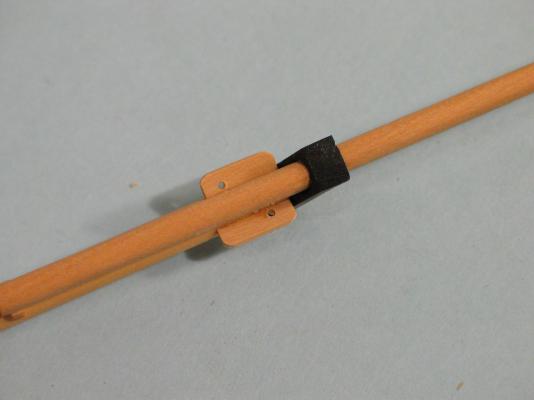
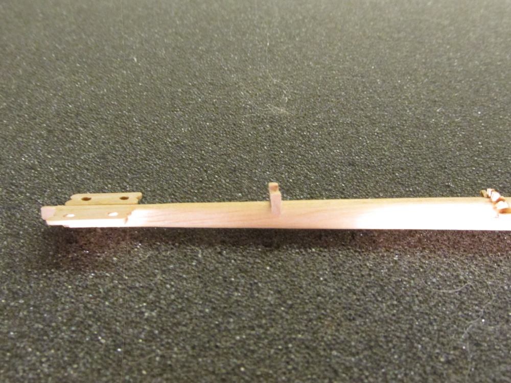
The cleats were glued into place.
- MEDDO, Mirabell61, JPett and 2 others
-
5
-
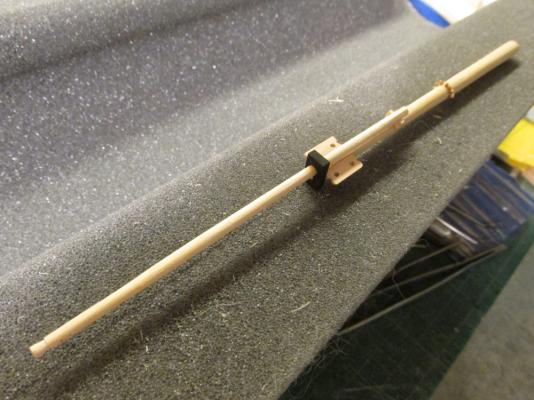
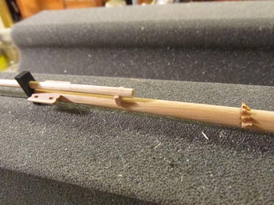
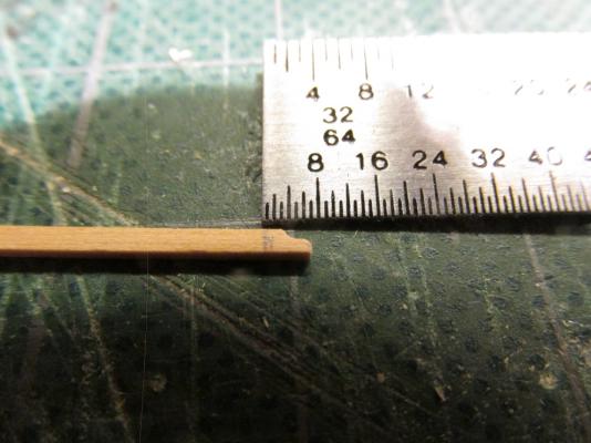
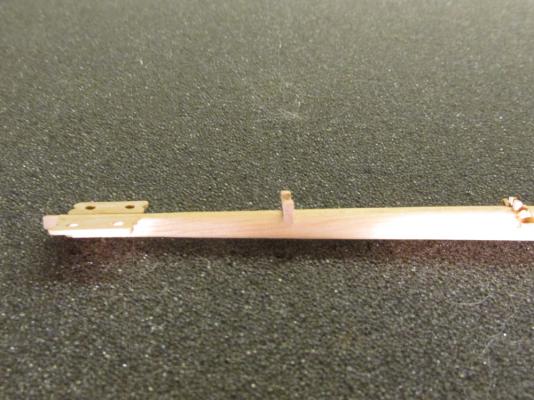
The bowsprit was then dry fitted into position on the bow to determine where and how the gammoning cleats were to be positioned. This was done by wrapping a single line from the fore end of the gammoning slot straight up and around the bowsprit and through the gammoning slot again. A pencil line was draw tracing the rigging line on the bowsprit. Based on Hahn’s plans, I determined there were 7 cleats that needed to be made. Using a piece of 1/32” x 3/32” boxwood, a corner was first filed off the stock piece and then an “S” curve was fashioned into that angle cut with a fine round needle file. The piece was then cut off and repeated for the next one.
- KenW, CaptainSteve and MEDDO
-
3
-
Studying the bowsprit bees in David Anscherl’s book a little closer, he stated:
“In earlier days the bees were fitted at an angle to form a shallow ‘V’ as seen from dead ahead. However by the time period of the Swan class, the bees were set horizontally.”
So since all the plans show horizontal bees which is confirmed by the fact the Swan class boats were built between 1767 - 1780 (per the title of Davis’s book) and the Rattlesnake was built 1781, I can assume the bees on her were horizontal as well; who am I to argue, James Lee notwithstanding.
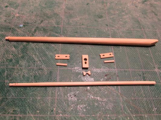
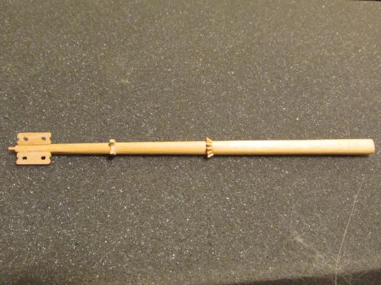
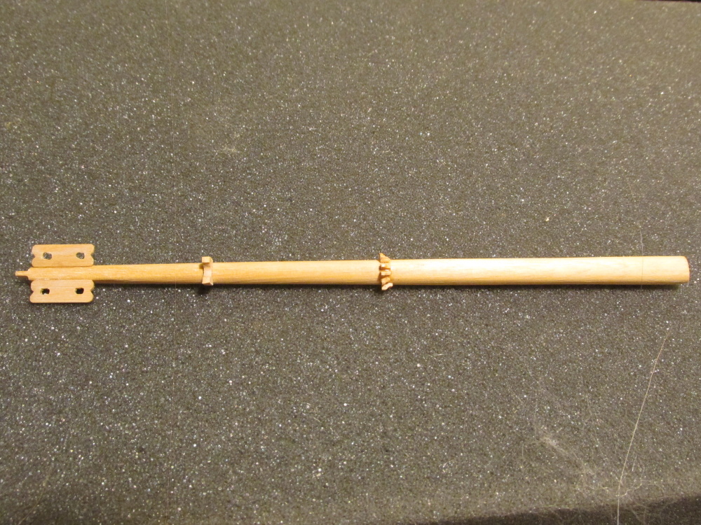
A new bowsprit was constructed as well as its jib boom filing and sanding by hand wooden dowels. My small wood lathe is still too big for this delicate work. The cap, saddle, bees, and the bee blocks were also made and then all the parts were assembled and glued.
- KenW, CaptainSteve, Martin W and 2 others
-
5
-
Martin, the reason you only needed two bee holes for the lines was that the other two were spares.
I still haven't decided whether to angle the bees or not. Lee states they should be; and Antscherl left them flat as shown by Hahn and the two kit plans. That's what so great about model building: consistent inconsistencies!
-
Based on the above and rounding out for 1/64 scale, I determined that the bees on my model should be:
Bees
· Length: ½”
· Width: 3/64”
· Thickness: 1/32” at the bowsprit
Bee Blocks
· Length: 25/64” rounded to 3/8”
· Width: 3/128” rounded to 1/32”
· Thickness: 5/64” rounded to 3/32”
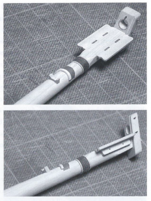
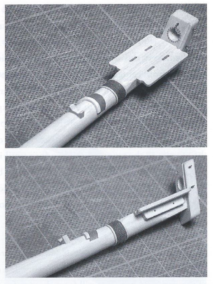
Here is a case where nobody agreed on the shape, dimensions, and number and shape of the rigging holes. As a confirmation as what the bees should look like, David Antscherl’s The Fully Framed Model, Rigging a Sixth Rate Sloop of 1767 – 1780, Volume IV, showed this:
Now all I have to do is follow David.
-
-
According to James Lees’ The Masting and Rigging of English Ships of War 1625 – 1860 the Bee’s dimensions are as follows:
Bees
· Length: Same as the length of the bowsprit cap
· Width: ½ the greatest diameter of the bowsprit
· Thickness: ¼ of the width at the edge next to the bowsprit thinning to ¾ width at the outer edge
Bee Blocks
· Length: 7/9 the length of the bees
· Width: ½ the bees width
· Thickness: 2” per bees’ foot length
Configuration
The bees stood up from the level at the outer edge by the thickness of the inner edge plus 1”
-
What I thought would be straight forward and fairly simple…well, I got an education. Hahn’s plans only had an elevation view which indicated the Bees were 3/4” in length x 3/64” in depth and the Bee blocks were ½” in length x 3/64” in depth; therefore no width, rigging hole pattern, or plan view shape were shown. The Practicum stated the bees were 1/8” wide and the bee blocks 1/32” square. Looking at the two kit plans, they indicated the bees were between 5/16” to a ½” length. Both the Practicum and the kit plans showed one rigging hole per side diagonal from each other all with subtly different shapes. Here is what the Practicum would have you build:


Rattlesnake by JSGerson - FINISHED - Mamoli - 1:64 - Using Robert Hunt’s practicum
in - Kit build logs for subjects built from 1751 - 1800
Posted
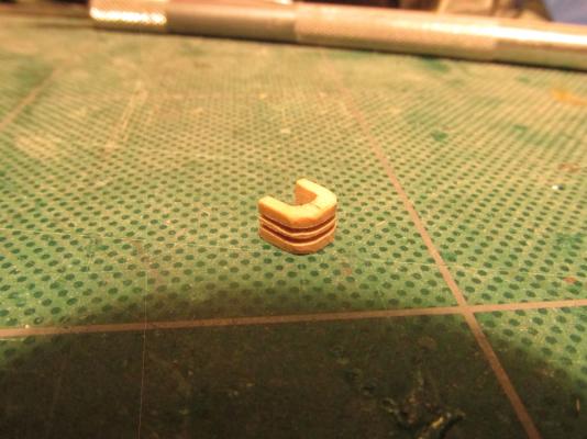
You can see from Hahn’s plan how the collars fit into place.