


JSGerson
-
Posts
2,156 -
Joined
-
Last visited
Content Type
Profiles
Forums
Gallery
Events
Posts posted by JSGerson
-
-
Great! How come you initially elected not to install them?
-
After the drying, the excess treenails were cut off, sanded, and finally coat of Wipe-on Poly applied.

-
Once the pieces were trimmed and sanded, the tree nails were drilled with a #70 bit. The tree nails were inserted and “glued” in place with Wipe-on Poly.
-
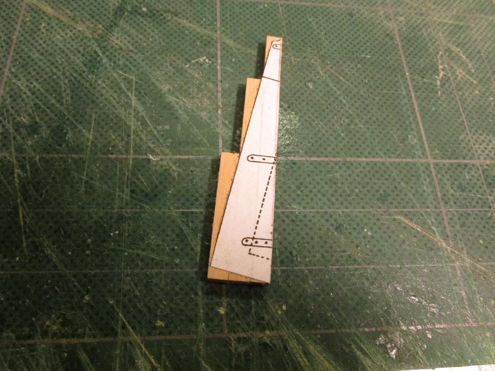
The pieces were then glued on following the line I traced from the drawing template.

-
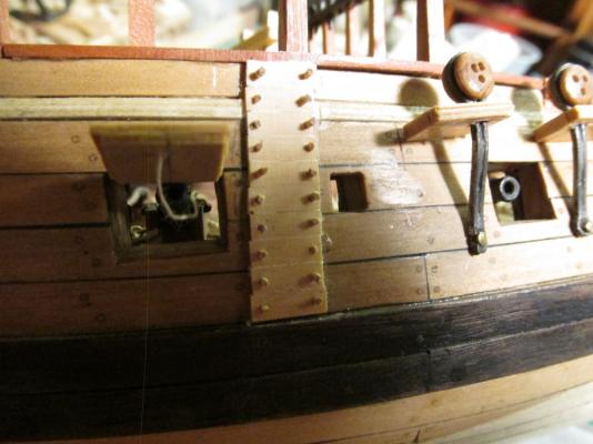
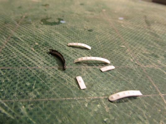
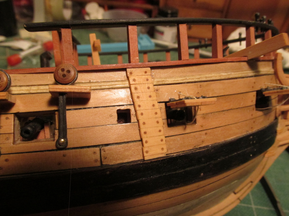
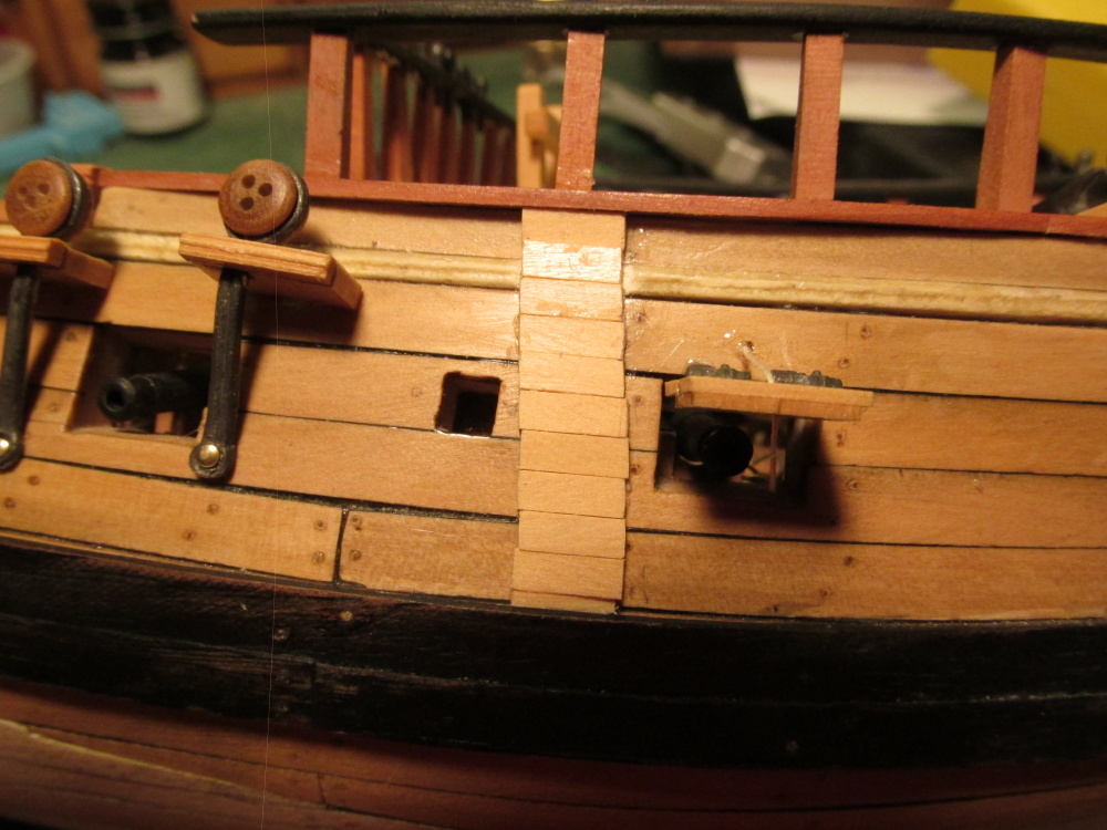
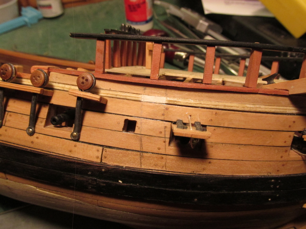
Before the anchor is installed the Practicum states there is a layer of planking between the second and third gunport that protected the hull when the anchor was raised up to the stored position. What the technical term for this is I don’t know but I’ll call it “reinforcing” planks. The practicum calls for 1/32” x 3/32 boxwood ¼” long to create them. As shown in all the plans they were laid out is a slight arc and appeared to cut through the thin molding strip just above the gunports. The photos in the Practicum show that Bob Hunt straddled the molding. I then looked at my collection of Rattlesnake model pictures which showed that some straddled, some cut through, and others appears to go over the molding. I reasoned that if the molding was left “naked” it would have been battered by the anchor so I opted to have the reinforcing cut through the molding.
-
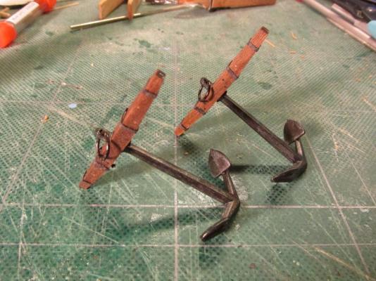
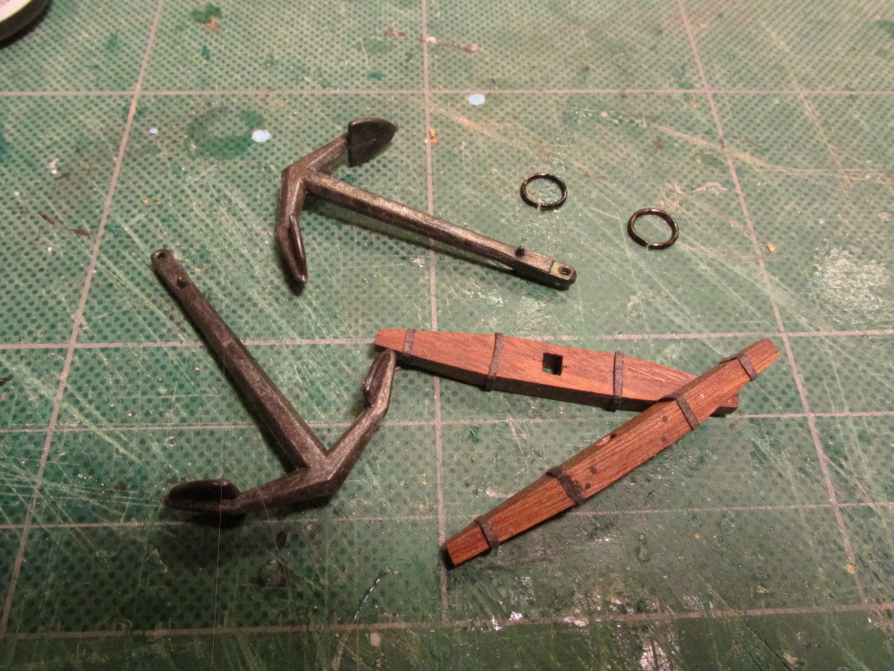
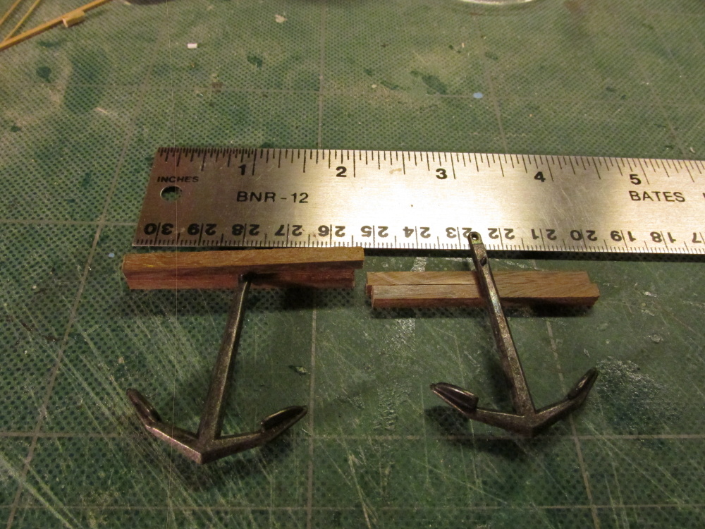
The last touch was adding the shank ring. The ring that came with the kit was shiny brass. Using the Sharpie pen again I colored the ring black.
-
Adding the “metal” bands turned out to be the trickiest part. The bands were made of 1 mm wide black paper. Trying to limit the amount of glue and still hold the thin paper strip in place without ripping it allowed me to practice some nautical vulgarity. I must be getting good at it, the cat ran away.

-
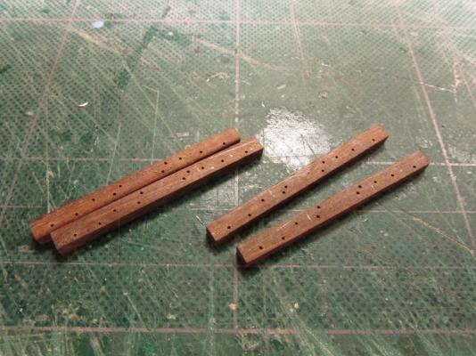
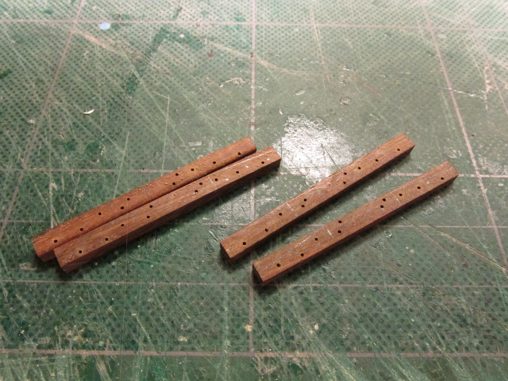
After marking up the stocks to indicate for the tapper I used my rotary disc sander to remove the excess wood. The treenails and “bolts” were made in the same fashion as the treenails used elsewhere on the model. They” were then inserted into the pre drilled holes. The only difference between the constructions of the two was that the “bolts” were colored black with a Sharpie pen. The bolts were also made a bit shorter to ensure they would fit flush upon insertion. I didn’t want to snip the dark ends off when everything was made flush. In the end, you can barely see the treenails and one could argue this step could have been skipped and no one would be the wiser. Still, I’m glad I did do it.
-
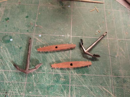
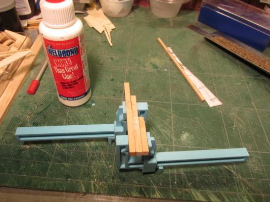
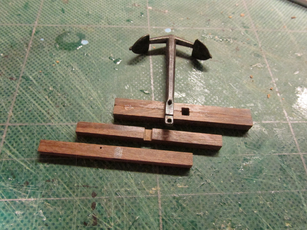
The shank hole was measured and chiseled out taking caution to ensure that both pieces of the stock mirrored each other to create a nice tight square hole. The two halves of the stock then glued together.

-
Using the Dremel drill press rig and a #70 drill, holes were drilled into the wood to accept the treenails and the pseudo bolts. The “bolts” holes were drilled next to the shank-hole position before any shaping of the stock. This was to make it easier to use the drill press.
-
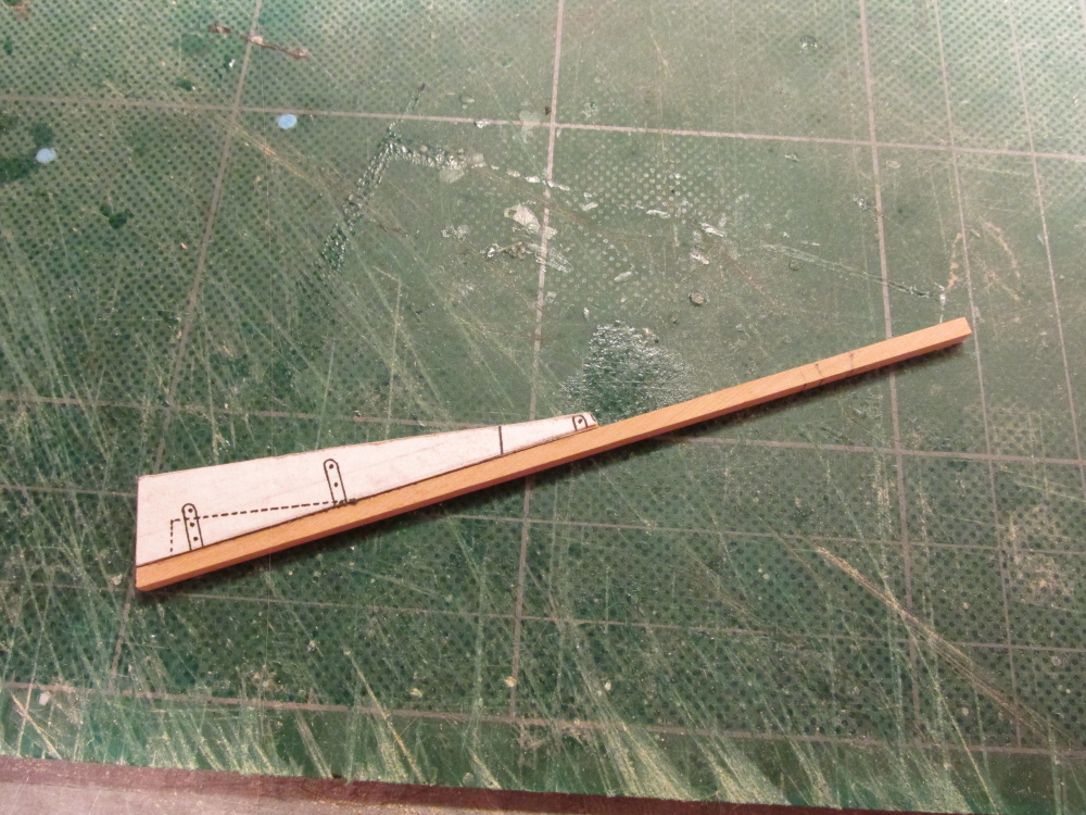
The anchor stocks are made of two pieces that are bolted and treenailed together. The stock walnut pieces were cut that two pieces matched the overall dimensions indicated in the Practicum

-
I am planning on using black paper as well. According to Blue Ensign the strips are just 1 mm wide. At that thickness, no one can tell what they are made of. Your model looks real nice by the way.
Jon
-
Thanks for the link to the workshops. Even if I can't make it to them, the website seems to have a lot of goodies for reference.
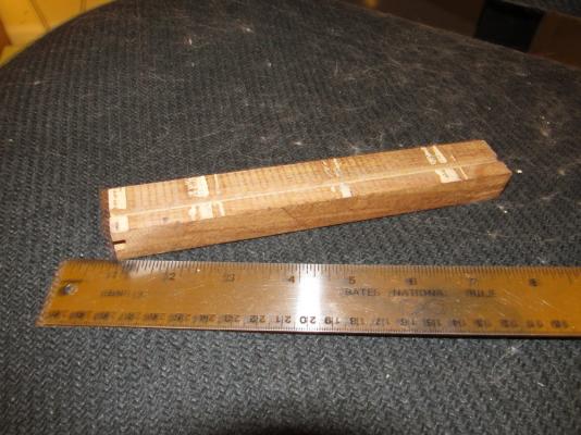
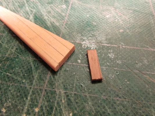
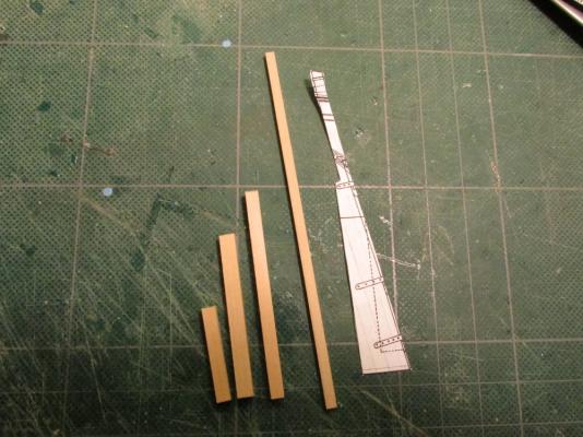
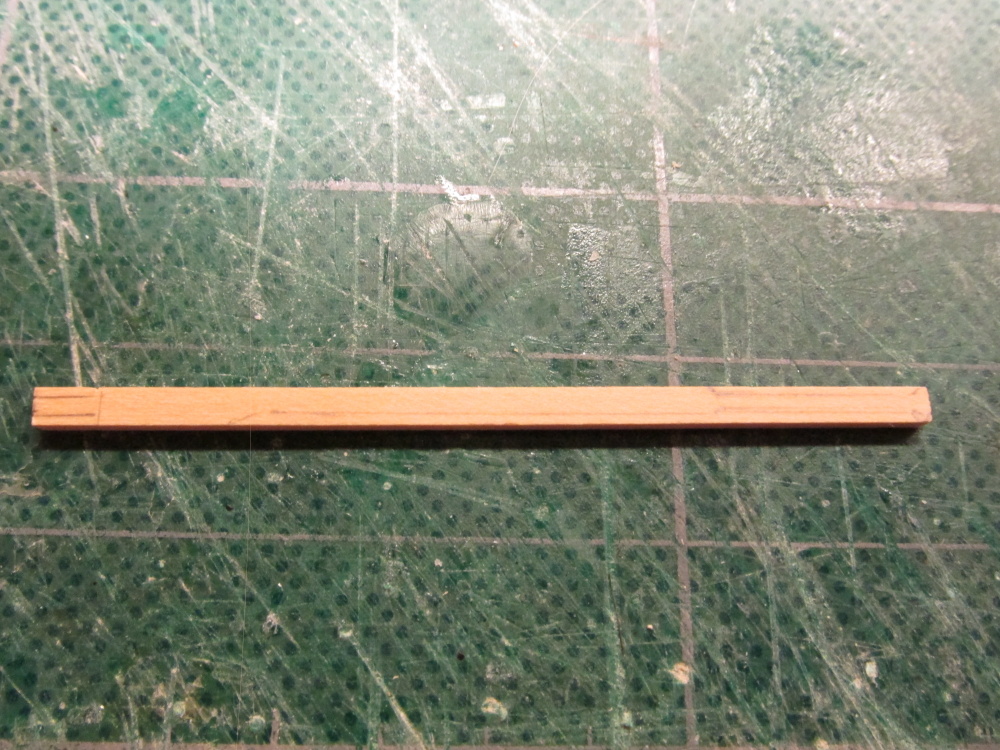
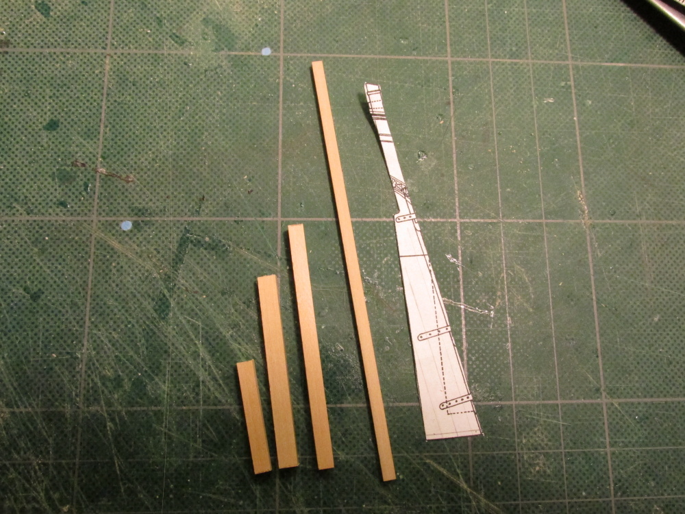
Per your request Martin, here are pictures of the wood I got. The top photo is of the walnut and had already sliced off the long grooved edge. You can still see and edge on the short end and what looks like the remnants of a groove along the face. I used the large tooth saw blade on the Byrnes saw to cut that edge so that two pieces fell off that formed the groove leaving a flat edge. From those two pieces I created my blanks using the fine tooth saw blade for the anchor. You will see the blanks when I post the anchor build.
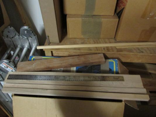
The other image is of the teak wood (bottom 3 pieces) and the cherry wood (top). NOTE: there are TWO rulers shown. I had the "guy" slice a couple of pieces of the teak so I could handle it in the Byrnes saw. The cherry was a little thicker but shorter. I might have to make two passes to cut them as the Byrnes saw only cuts to an inch thick.
All told, I invested $20!
Jon G
-
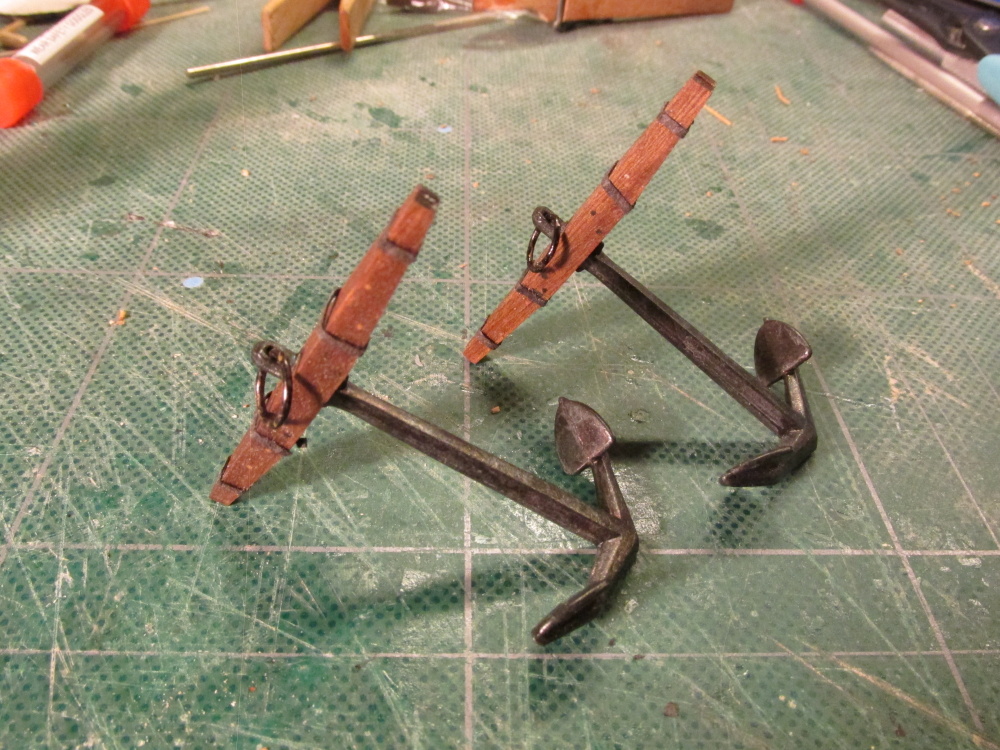
The Anchors
The Practicum states that the anchors that came with the Mamoli kit had over sized walnut stock pieces although the anchors themselves weren't too bad. Therefore the Practicum instructed the builder to use 2 pieces of 5/32” x ¼” x 1 13/16” boxwood for the two anchors. Why boxwood; probably because neither the wood package from HobbyMills nor the kit has this stock size in walnut.
I chose not to follow the Practicum for the anchors except for the dimensions of the wooden stock. It didn't mimic the way actual anchors were put together
.
Having followed Blue Ensign’s wonderful discussion on anchors for his build of the 1/64 scale HMS Pegasus, I chose to followed in his footsteps more or less. He did use walnut and his construction of the anchors was more realistic than the Practicum.
First step was to get some appropriate sized walnut. I had two obvious choices, buy mail-order or buy local. Since I needed it now I went looking on the web for a local wood supplier other than construction lumber. Since there was no exotic woods store in my town, who would carry walnut wood? A furniture manufacture… none local; a cabinet maker…nope; a furniture restorer…BINGO! I was able to get a nice piece of miscellaneous walnut from this “guy” who restored stuff for an interior decorator store. He even threw in a slab of teak and one of cherry all for a small nominal fee. The walnut had some grooves for a tongue and groove piece of something and was finished on one edge. But a few trips through the Byrnes saw and I had what I needed with plenty to spare.
-
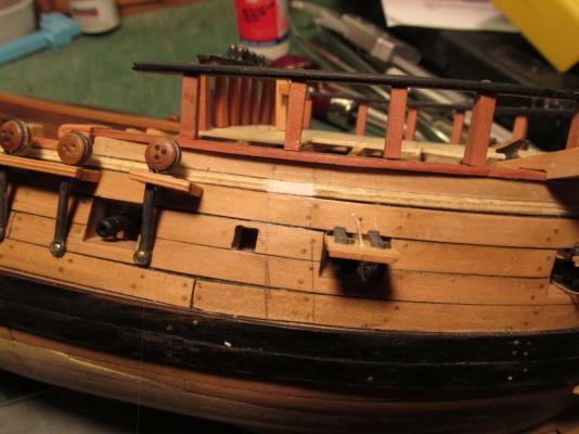
The rudder and post have been installed as well as the pinties on the hull. As you can see the rudder post comes up through the deck real close to transom. That’s not the way it should be, but as I had explained earlier in this blog, that’s the way it is. You will also notice I added the reinforcing blocks. They came out a bit larger than I thought they would so they may or may not stay in their present configuration. It all depends if I can remove them easily enough to modify them. I’m leaving the tiller off as well as the binnacle, which was made earlier, until later when the chances of breaking them will be reduced.
-
Thanks for the tip.
BTW, I got my copy of Ship Modeler's Shop Notes Vol II signed by the editor Daniel Pariser and one the associate editors, Paul Fontenoy. Even Jim Brynes was there with all his goodies!
-
Due to the errors that I made during the early part of the transom construction which I think I discussed at length, I knew I would have problems with the rudder post. On my model, I had to make the rudder post opening butt against the transom and even then I had to fudge a bit with the post. Actually I made the rudder post at the same time I made the post opening using the post as a guide to position the opening. Once I knew they would fit I put the post aside till it was time to use it. As for the tiller, I don't think I will have a problem due to the fact the rudder post is so far back.
The conference was great. Over the course of 4 days, we had 12 speakers and 3 tours. The speakers were excellent, all top notch experts in their areas. They talked everything restoring actual relics including the USS Monitor, modeling techniques, history of private boat building in Racine WI, among others. The tours included touring 3 WWII warships (carrier, destroyer, & sub), visiting the first sub to sink a warship, the Hunley, and a tour of Ft. Sumter. So I'm planning to go to St. Louis next October for the next conference.
-
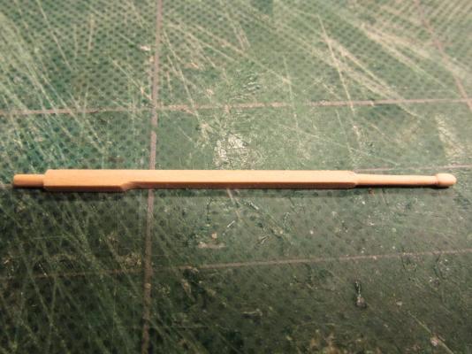
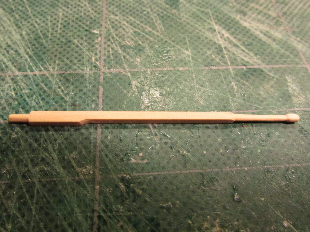
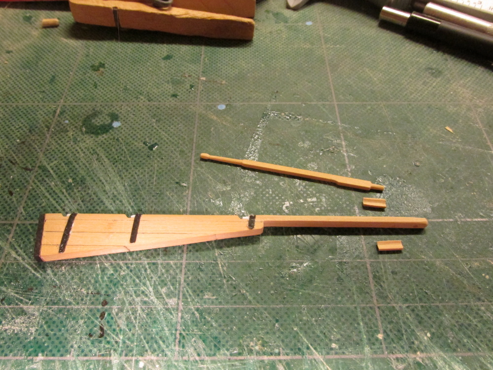
In a sentence that could be easily overlooked, the Practicum instructs the builder to drill a 1/16” hole in the rudder post for the tiller and then goes silent on the construction of the tiller for another 23 pages. I decided to construct the tiller now while everything was off the model and easy to manipulate.
The Practicum instructs the builder to use 1/16” x 3/32” boxwood to make the tiller. That’s it, no other instruction on shape. The 3 plans show a simple straight rod going through the rudder post. The Mamoli and MS plans show some reinforcing blocks where the tiller passes through the post but no real detail. Bob’s tiller looked quite nice and structural stronger than what the plans showed with no reinforcing blocks. The blocks would add the material and strength back that was drilled out for the tiller hole. So my tiller is based on Bob’s photo of his tiller and the reinforcing blocks.


-
The Practicum claimed that the cast grudgeons and pinties parts that came with the kit were too thick and the spacing between the two sides was too large to use. The Practicum called for them to be made out styrene. Since they were to be painted black, there would be no hint as to what material they were made of. I suppose I could have made the pinties out of card stock or paper and the skipped the grudgeons since they would not be seen. But I didn't. If this were a larger scale model, I might have tried to make those pieces out of metal and blackened them (which by the way I’ve never done), but since it wasn’t, I didn't. I just wanted to let anyone know I did think about it. The Practicum called for the pinties to be made out of .015” x .060” styrene and the grudgeons .060 styrene rod. I used .050 styrene rod as I didn't have any of the other. It made no real difference.
The pinties have rivets so using a dull but pointy instrument, I impressed on the backside of the styrene straps to make bumps on the opposite side. The straps were painted black except on their backside. I wanted a clean surface for the glue. In this case, I used “airplane” glue.
-
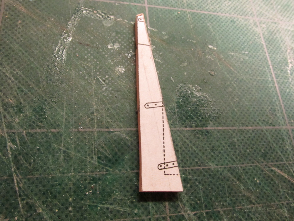
5/32” notches were then cut into the tiller edge to accommodate the grudgeons (pins) and pinties (straps). The notch had a top edge straight cut while the bottom curved. This was accomplished using the fine tooth saw from my miter box, a micro chisel, and some needle files. In hindsight, if I were to do this again I would have made the notches a bit longer, at least 3/16”. In order for the rudder to be removed, a working space of one strap as a minimum would be required. Therefore 2 straps widths and one strap space is about 3/16”.
-
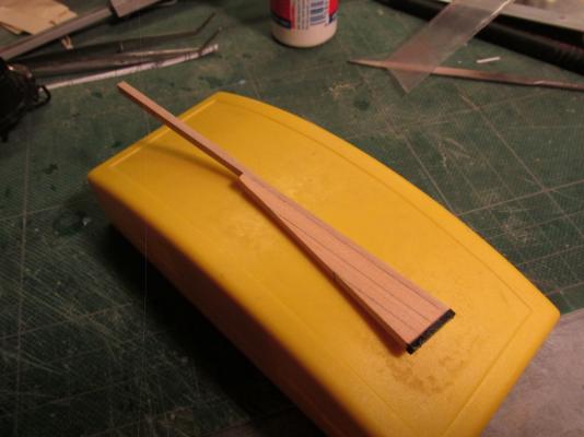
The false keel was added and the whole assembly was then shaped to match the keel thickness. The tiller edge was rounded over to allow the rudder to rotate even though it will be glued fixed in place. The false keel was then painted black.
-
-
Rudder and Tiller
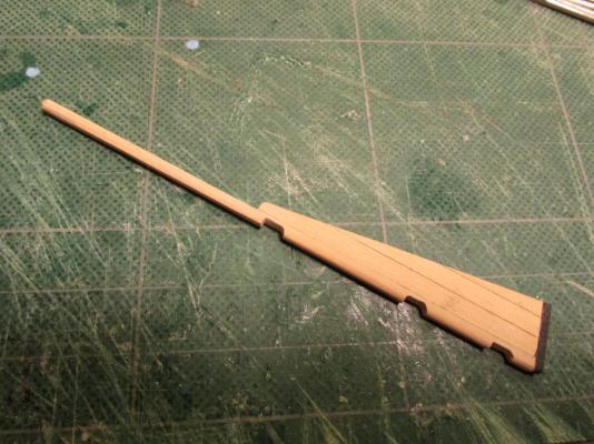
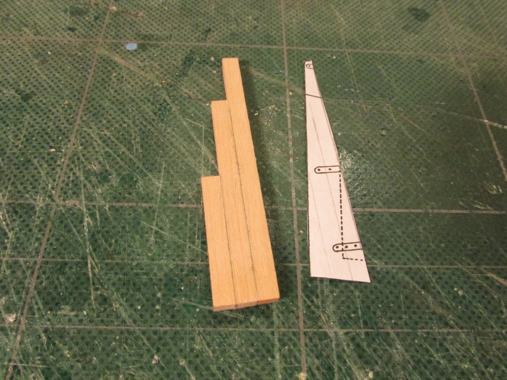
It’s time I spent working on the other end of the ship and add the rudder and tiller. Per the Practicum, the rudder is made of three pieces: 2 boxwood pieces for the rudder and tiller, and 1 ebony piece (in my case black painted walnut) for the false keel extension. Based on what I have seen in this website and other sources, the rudder is not a solid piece wood. The Mamoli plans as well as the Model Shipway plans both show a composite build albeit slightly different from each other. Hahn’s plans do not address the makeup of the rudder. I chose to follow the Mamoli plan.
The Practicum calls for the rudder post to be made of 1/8” square boxwood. Bob Hunt used a single piece of 1/8” boxwood, but because the wood package does not contain a piece of the rudder size, the Practicum instructs you make it from two pieces of 1/8” x ¼” edge glued to give sufficient width. If I have to edge glue two pieces, I might as well edge glue 3 piece of 1/16” x 1/8” to match the Mamoli plans. Since my wood package didn't have 1/16” x 1/8” boxwood, I used 1/16” x 5/32” and used my Byrnes dimension sander to reduce it down 1/8” thick. Hopefully I didn't use too much of the 1/16” x 5/32” boxwood for whatever it was later intended.
-
I'll throw in my 2 cents about tree nailing:
Point one, ships used treenails.
Point two, tree nails were not used as a fashion statement.
Therefore on my Rattlesnake, I did nothing to enhance the contrast to make them stand out. I like to think of the model like an onion. As you peel back on layer there is another. So the closer you look, the more detail you see. The effect I believe, should subliminal. Why does one model look better than another. Many times you can't put your finger on it, but I think it boils downs to craftsmanship, presentation, and the little details. Treenails are the little details that you may not a first realize are there but enhance the overall effect.
That said, I'm really a novice at this. The Rattlesnake is my first POB sailing ship so take this with a grain of salt.
- src and popeye the sailor
-
 2
2


Rattlesnake by JSGerson - FINISHED - Mamoli - 1:64 - Using Robert Hunt’s practicum
in - Kit build logs for subjects built from 1751 - 1800
Posted
The anchor builds are based on Blue Ensign's build of the HMS Pegasus, a beautiful build chock full of goodies to contemplate. Thanks BE!