


JSGerson
-
Posts
2,480 -
Joined
-
Last visited
Content Type
Profiles
Forums
Gallery
Events
Posts posted by JSGerson
-
-
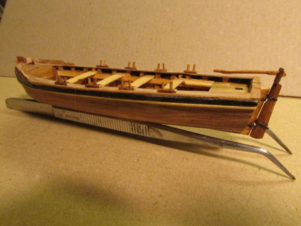
Now the 8 oars are complete.
- CaptainSteve and Martin W
-
 2
2
-
I might have tried the bamboo forks, but I did not find any immediately available. The oars were not difficult to fabricate in any case. It's a good idea though. Maybe when I finally build my Conny in the next millennium I'll use that idea.
-
That's fairly close to what Steel has (if I read his chart correctly). An inch or two difference at 1/64" scale isn't going to amount to much so I think I'm OK. Thanks for your input,
-
Actually Scott, this is fairly recent stuff that went missing and it happened twice.
-
The dimensions were based a chart in Steel for a boat breadth of about 6 feet. Everything was reduced down by about 1/64
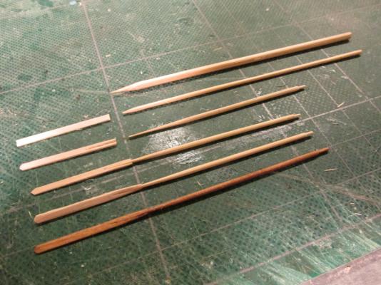
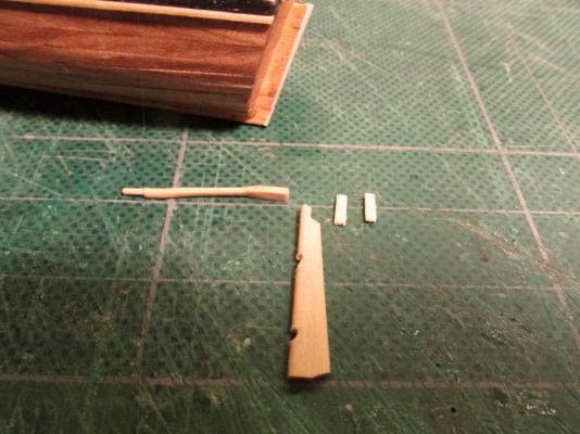
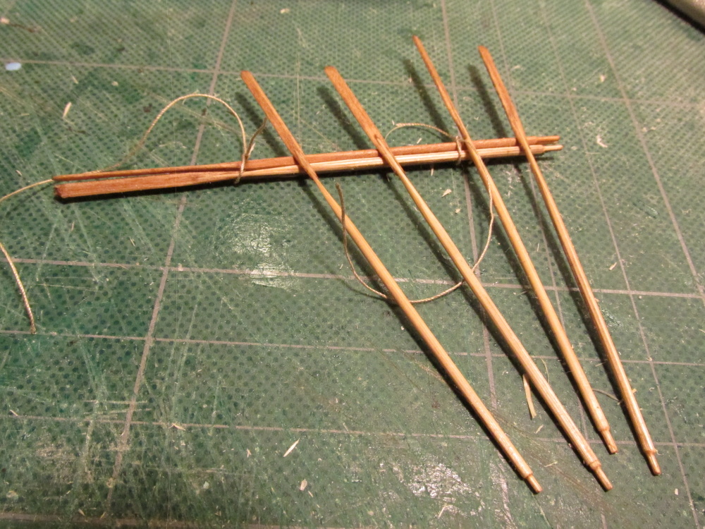
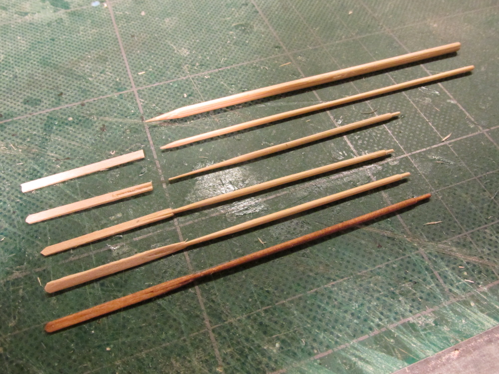
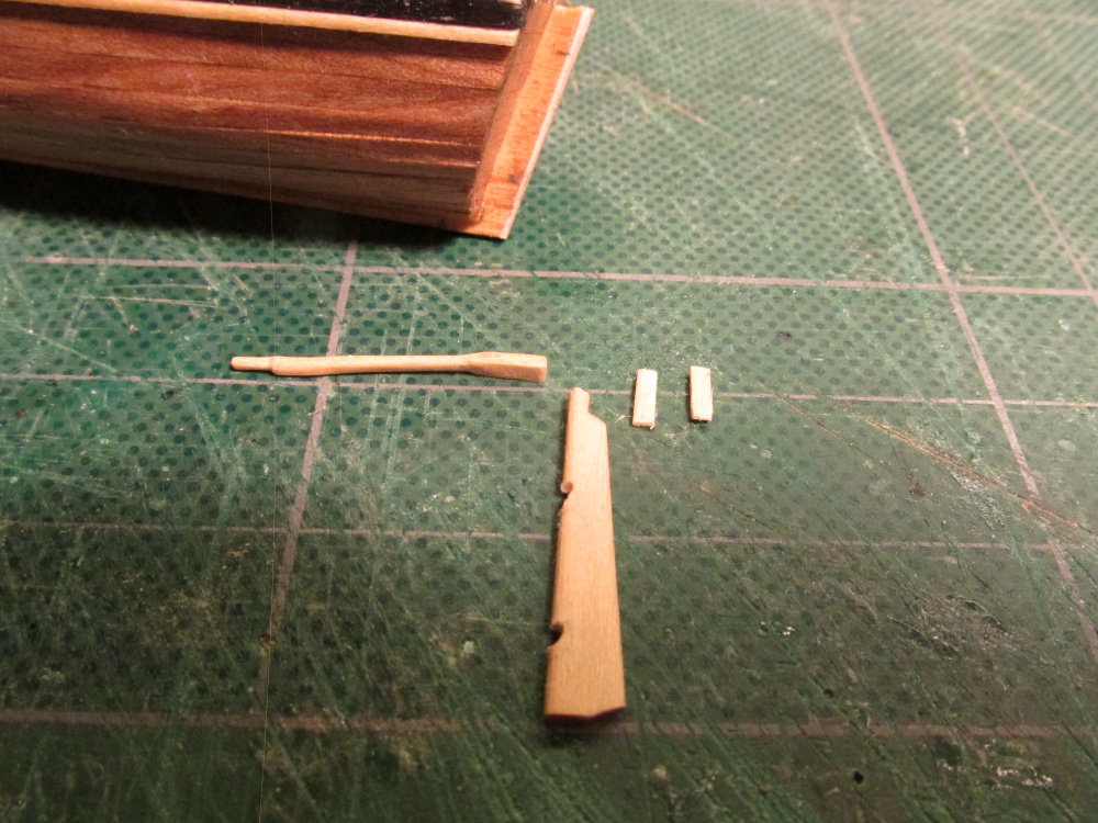
The materials for the oar were bamboo barbecue skewers and 1/32” x 3/32” basswood for the oar blade. After splitting a skewer to about 3/32: square, a draw plate was used to reduce it down to about 1/16” diameter. Unfortunately I couldn't use the Byrnes draw plate because it was for finer holes only. I had to fall back to my larger pre-Byrnes drawplate which left something to be desired.
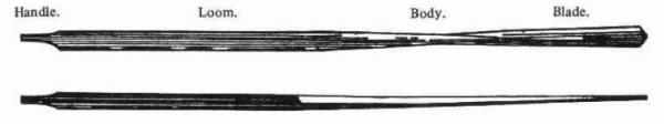
The skewer was then cut to about 3” in length, and tapered to match the shape shown. A handle was carved on the blunt end. The tapering was flattened so it would slide into a very narrow V-notch in the blade.
The two pieces were then glued. Once dry, final shaping was done to the blade and the whole assembly was stained with Early American Minwax Wood finish.
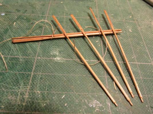
A total of 8 oars have to be made. As you can see from the image below, I completed one; and started the remainder.
-
Boat Oars
What is a boat without oars? The kit was for the boat only; any accessories, you were on tour own. I based the oars for this boat on The Art Making Masts, Yards, Gaffs, Booms, Blocks and Oars as Practiced in the Royal Navy and According to the Most Approved Methods in the Merchant Service, 2nd edition, printed for Steel and Goddard, London, 1816. It’s English Royal Navy and published later than the Rattlesnake 1781 commission date, but it was the best reference I had. I’m guessing that any differences between an English boat oar and an earlier American boat oar would be minor and not too noticeable at this scale (I hope).
-
PLEASE NOTE
Dear Readers, it has been brought to my attention that more than a dozen or so images in this log have vanished for some unknown reason. You can see the frame, but no picture. Twice now I've had to go back and replace the missing images. If anyone knows how to prevent this, please let me know. If anyone notices images missing please let me know so that I may replace them. Unfortunately, some of those image were provided by you, the reader in your comments to me so I can't replace them. If they are yours, please be so kind to repair your comments.
Thanks
Jon
-
I don't know if it's my computer or the site, but your images at the top of page 11 of your log are missing (at least I can't see them). I had the same problem with my log and had to replace 5 pages worth of images.
-
I'm working on the oars, so stay tuned
-
FINAL THOUGHTS
Here are some final thoughts based on a question I received from bandlc4
Great build log. I am using it to try and get back into modeling and have a question for you.
You added some wood to “form 1” instead of trusting the plan. Did you regret that or do you still recommend I do the same. I ask because I see that you had some problem with the forward Bow bulkhead after the planking was done and you used wood to fill in around it before applying the veneer.
If you were doing it over, what would you do with “form 1”?
This was my first small boat build, as well as my first upside down build, and my first Plank on Frame build, so I was learning as I was going.
The problem with the kit was that it was a $5 kit (on sale from $8). The Kit instructions stated that the keel was made of airplane plywood - it wasn't. It was basswood, the plywood would have been much stronger. The ribs on the jig had to be bent to form, I would have preferred that they had been cut to shape and there were all of ribs at the beginning and not stuck on later. That would have provided the planking strips with more support and insured proper shape. I would have preferred boxwood which is hard wood instead of the soft basswood. Another builder on the same model started over and replaced all the wood with boxwood and pear. Neither one of us planned to paint the boat.
When I went to create the top cap, I realized that my bow stuck out further on the stem than the plans showed. I thought I was following the plans meticulously, but because the plan's pictures were of such low resolution, you couldn't see the detail in the bow clear enough. As a result, my bow bulkhead ended up too small for what I built - my bow should have curved more tightly to the stem and then the bulkhead would of fit (I assume).
Although this is a small, "simple" model, I would not call it a first timer's model for it requires some boat building experience. If I had to build it again, and I could because the plan shows all the parts to scale, I'd cut the ribs to shape, which I find much easier than to bend, and add more of them to the jig. The hard part would be to create the additional ribs where the hull curves toward the bow. Not sure how I would determine the correct shape for the ribs there. That would ensure the bow bulkhead fits. By the way, the other builder I mentioned ran into the same problem with that bulkhead.
That all being said, it was a fun build and a good learning experience. I hope I answered your question and I wish you the best in your endeavor.
Jon
-
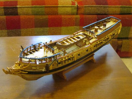
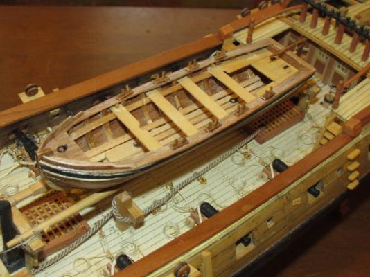
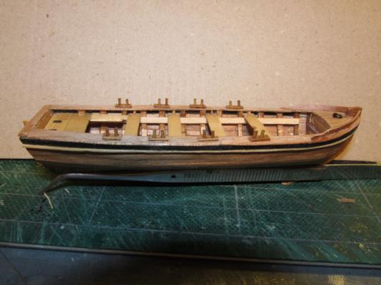
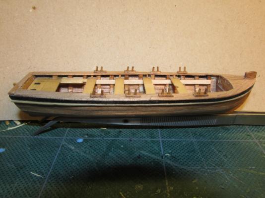
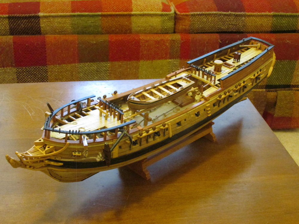
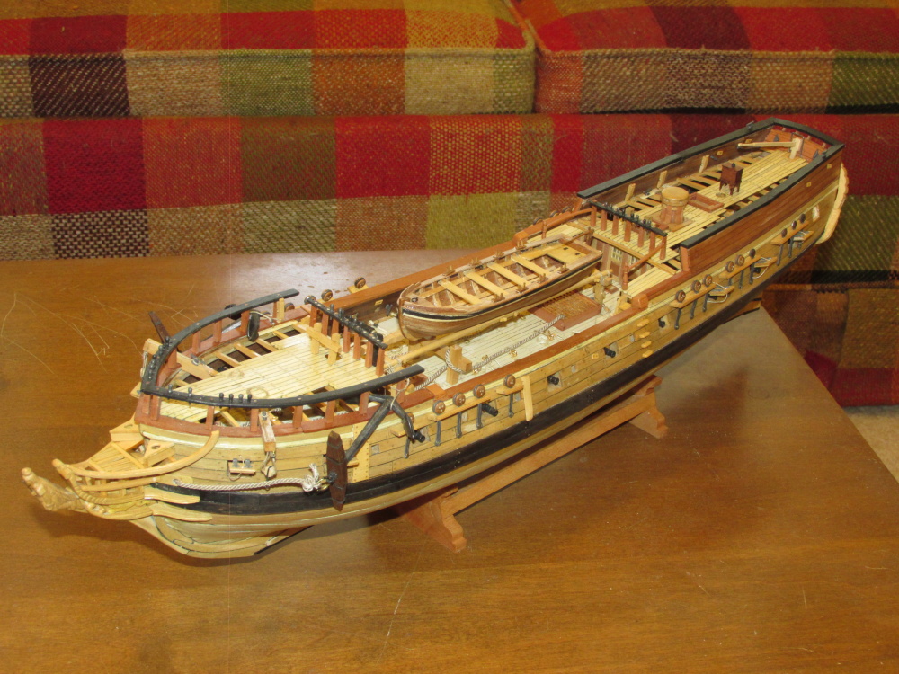
Here is what it looks like on the Rattlesnake (prior to permanently lashing it down)

- Aussie048, petehay, GrandpaPhil and 3 others
-
6
-
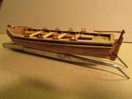
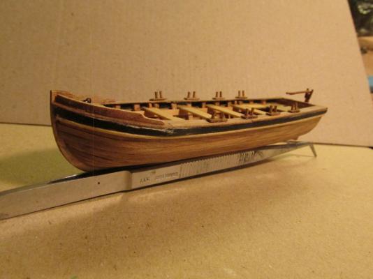
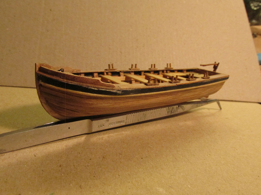
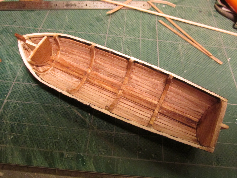
The final ship’s boat build is shown

- Aussie048, justsayrow, CaptainSteve and 2 others
-
5
-
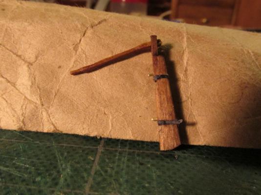
After the pieces were assembled, the basswood parts were stained with Early American and I added paper hinges colored black with a Sharpie pen. Because where the rudder post edge and the rudder edge meet are rounded, it made for a poor mechanical glue point. I added a couple of pins for a strong joint.
-
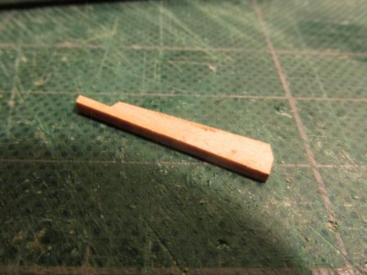
I had noticed that a lot of tillers pivoted vertically either for storage when the rudder was removed or for easier access to the boat. Although I didn’t plan on mine being functional, I wanted it to look like it could move. This required two short pieces to be added to the tiller post. The tiller itself was carved with a slight S-curve.
-
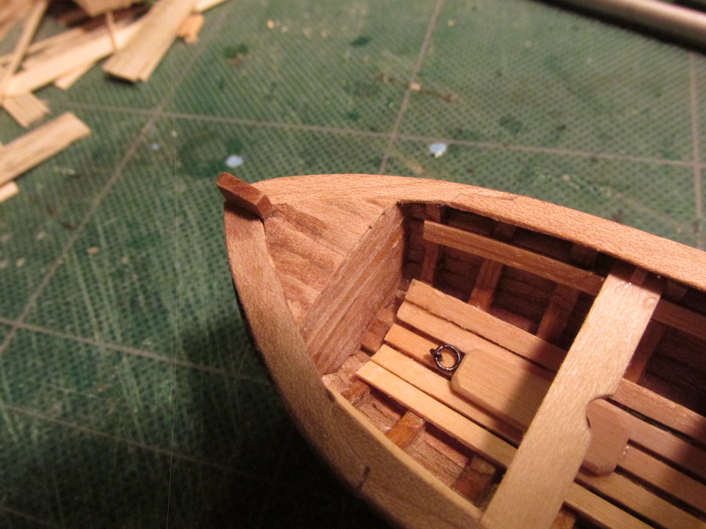
After looking at a lot of small and ship’s boats, I came to the conclusion that most of the boats I saw did not have the high stem post, so I chose to leave it off. Had I straight glued the broke piece back on, it would have remained fragile which would mean I would have had to pin it and risk breaking it some more.
All that being said, the rudder was now too tall for what I wanted to do so, the tiller post was cut down a bit.
-
-
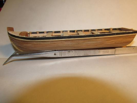
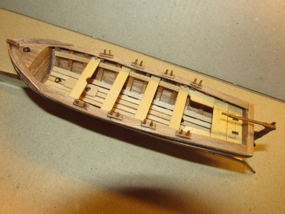
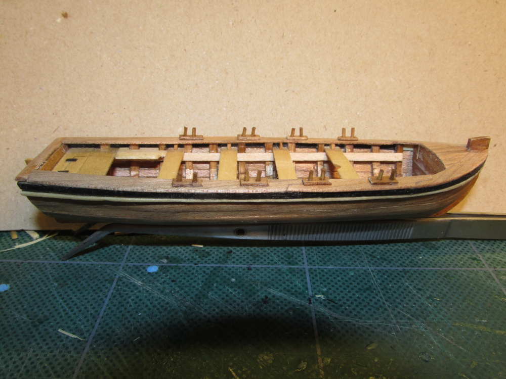
A strip of wood, which I think is called a washboard, was added to each side of bow as well another eyebolt and ring to the bow deck. Also notice that the oarlocks were moved after I was informed that I had inadvertently installed them on the wrong side of the thwarts. As originally installed, the rowers would have to face forward and row the boat backwards.
- Aussie048, Marcus.K., CaptainSteve and 3 others
-
6
-
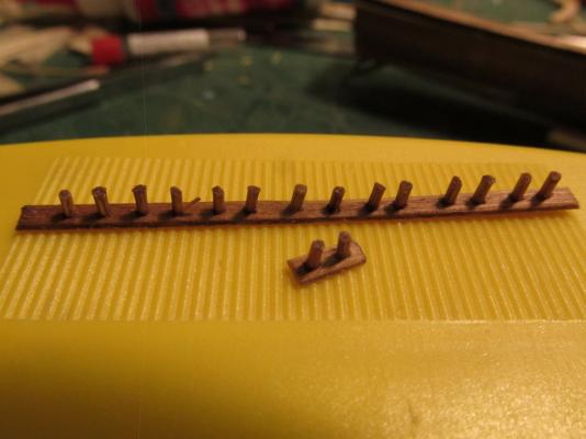
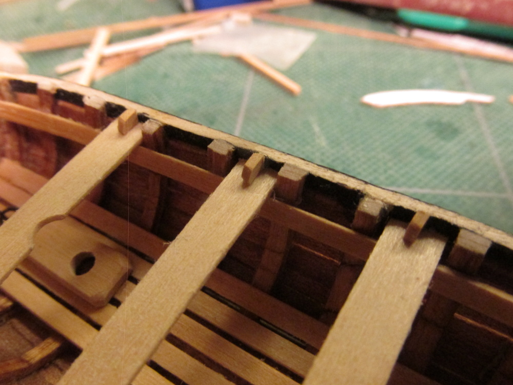
The oarlocks were made of bamboo pieces just like one would make treenails, about a quarter the width of the soon to be made oars (about 1/32”) and placed into a pre-drilled kit supplied basswood planking strip. Initially the holes were drilled and the oarlock inserted. Their heights were adjusted and then the whole assembly was stained with Early American. The stain temporarily “glued” the bamboo into position. After the stain dried, the excess was cut off from the bottom and sanded smooth. The oarlock assemblies were then cut off and glued into position onto the rail cap locking everything – the rail cap, oarlock plate, and the bamboo with a single dab of CA glue.
- Aussie048, justsayrow, hexnut and 1 other
-
4
-
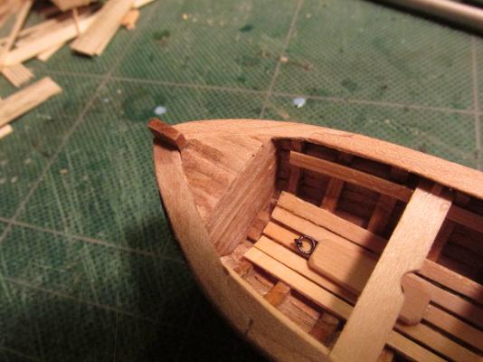
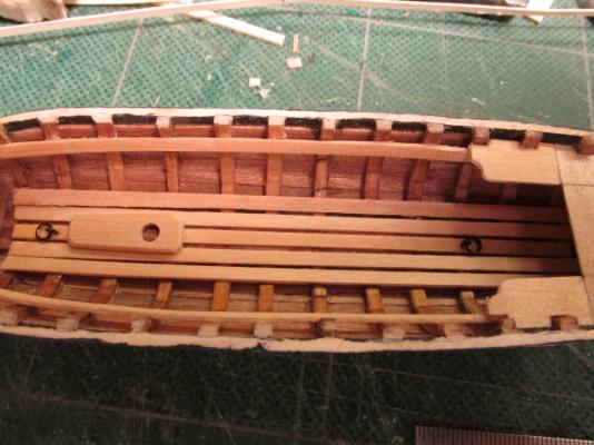
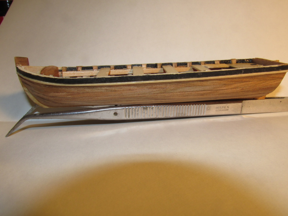
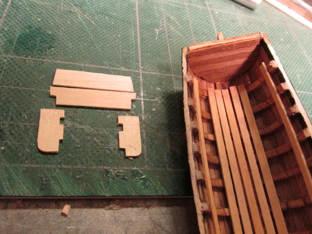
The bow was covered with teak plank.
-
These were glued in place, trimmed and sanded.

-
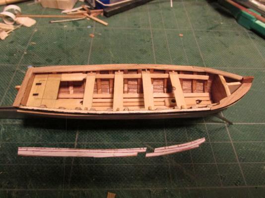
The top rail was made using a template traced from the model. If I had made the model perfect it would have matched the plans and I could have just cut the template directly from them. Since it wasn’t, I couldn’t. Each side template had to be cut in two places to create the splines for the three pieces of 1/32” x 3/32” Teakwood to accommodate the boat’s curve. The top of the transom was ¼”.
-
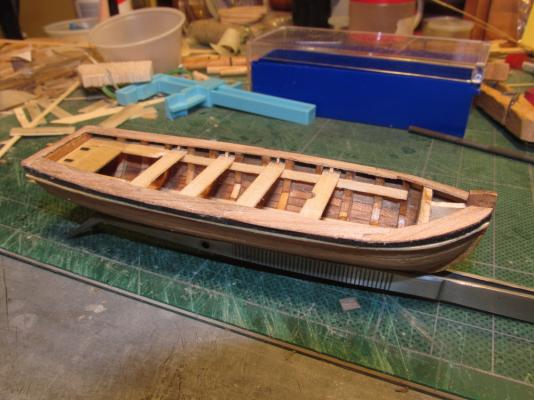
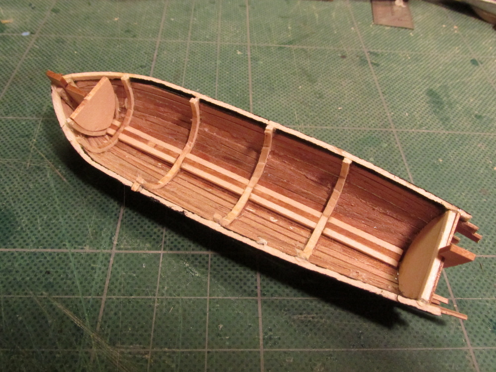
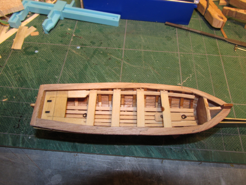
I noticed on many models, that the thwarts had little braces (knees) securing them to the hull so I added those. I tried to round the corners, but they were so tiny I could barely hold them steady, let alone file them. As it turned out in the end, you can hardly see them.

-
The seat pieces were cut and trimmed to fit and glued into place. The “hinges” are nothing more than pieces of black paper that were added when I Poly-wiped the wood. The remainder of the thwarts (seats) were supported by the risers (support strips). The forward thwart had a half round notch cut out for an optional mast.
- mtaylor, themadchemist, KevinR and 1 other
-
4
-
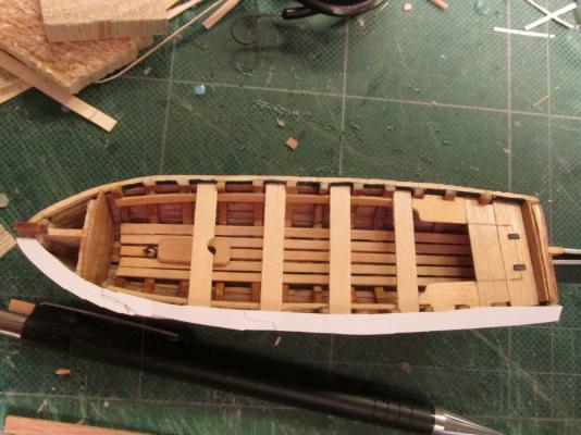
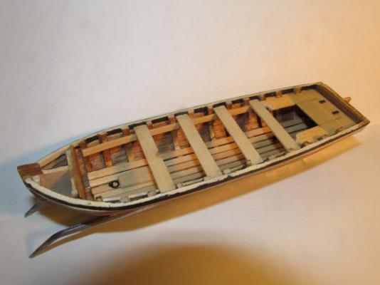
It seemed to me that all ship’s boats are basically the same at this stage of the build. Looking at all of my 46 Rattlesnake models images that I have collected from the internet, I selected the ones with clear/detailed images of the ship’s boat. Not one of them duplicated any other’s boat. Everyone was different. That meant I had free rein as to what mine was going to look like. Taking elements from the kit itself, the Practicum, other boats on or off the Rattlesnake, and reference books, I came up with my version.
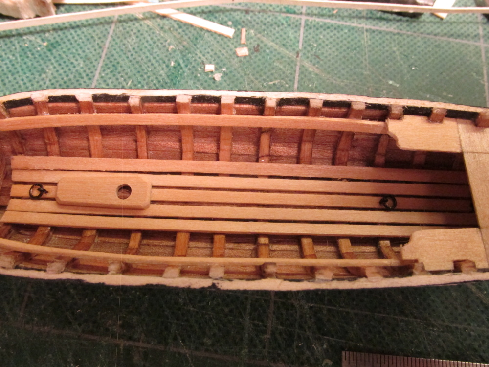
Like most boats, I created a backseat with two side seats. Some of the models I had seen had a lid over the back seat so I thought that would be neat to have. The lid was simply etched into the wood. Additionally I added a mast block (my own design since I didn’t have much to go on) and some brass rings fore and aft colored black with a Sharpie pen.


Ship’s Boat by JSGerson - FINISHED - Model Shipways
in - Kit build logs for subjects built from 1751 - 1800
Posted
The oars have been bundled and lashed to the thwarts. This completes the Model Shipways’ Typical Ship’s Boat building log. The lashing of the boat to the spare masts on the Rattlesnake’s deck will be covered in my Rattlesnake log.