JSGerson
-
Posts
2,137 -
Joined
-
Last visited
Content Type
Profiles
Forums
Gallery
Events
Everything posted by JSGerson
-
 I bought one of the cases offered by Model Expo for my 2-foot Rattlesnake. I bought the table it sits on separately from a furniture online site. I had to stain the case myself to match the table. Model Expo subcontracts out the cases to a workshop that makes the cases for them excluding the transparent material. I chose to use Plexi-glass in lieu of glass. And yes, they are not cheap. The case for my 4-foot long Constitution is going to be even more expensive.
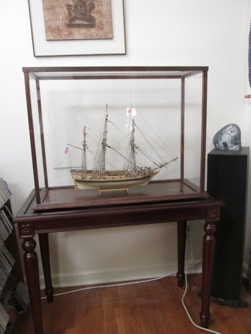
- 88 replies
-
- 3
-

-

-
- Constitution
- billing boats
- (and 1 more)
-
You've got something to be very proud of. I'm a big believer in display cases to protect your hard work from possible damage and dust. Can't wait to see see its final display area. Jon
- 88 replies
-
- 2
-
-
- Constitution
- billing boats
- (and 1 more)
-
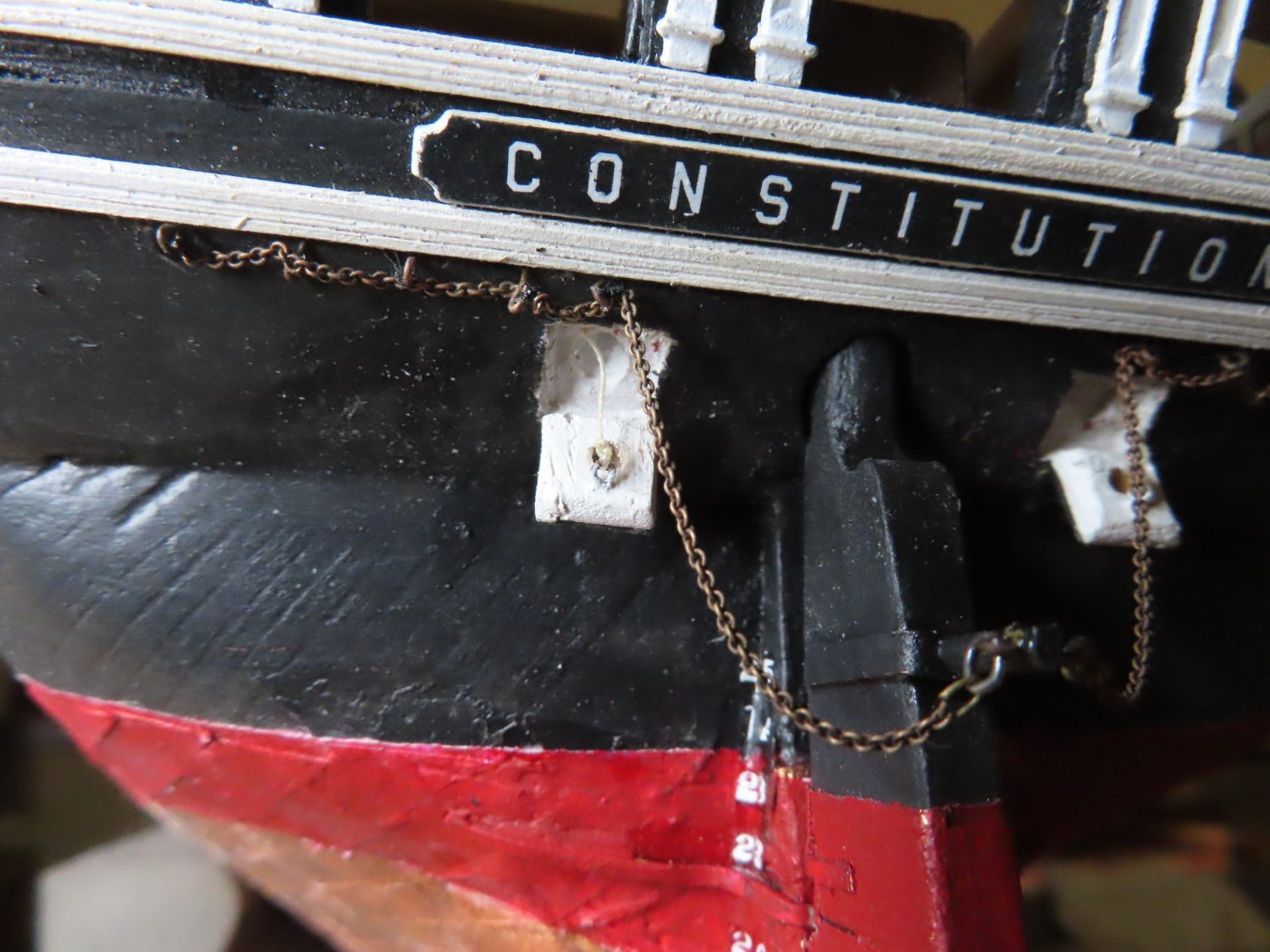
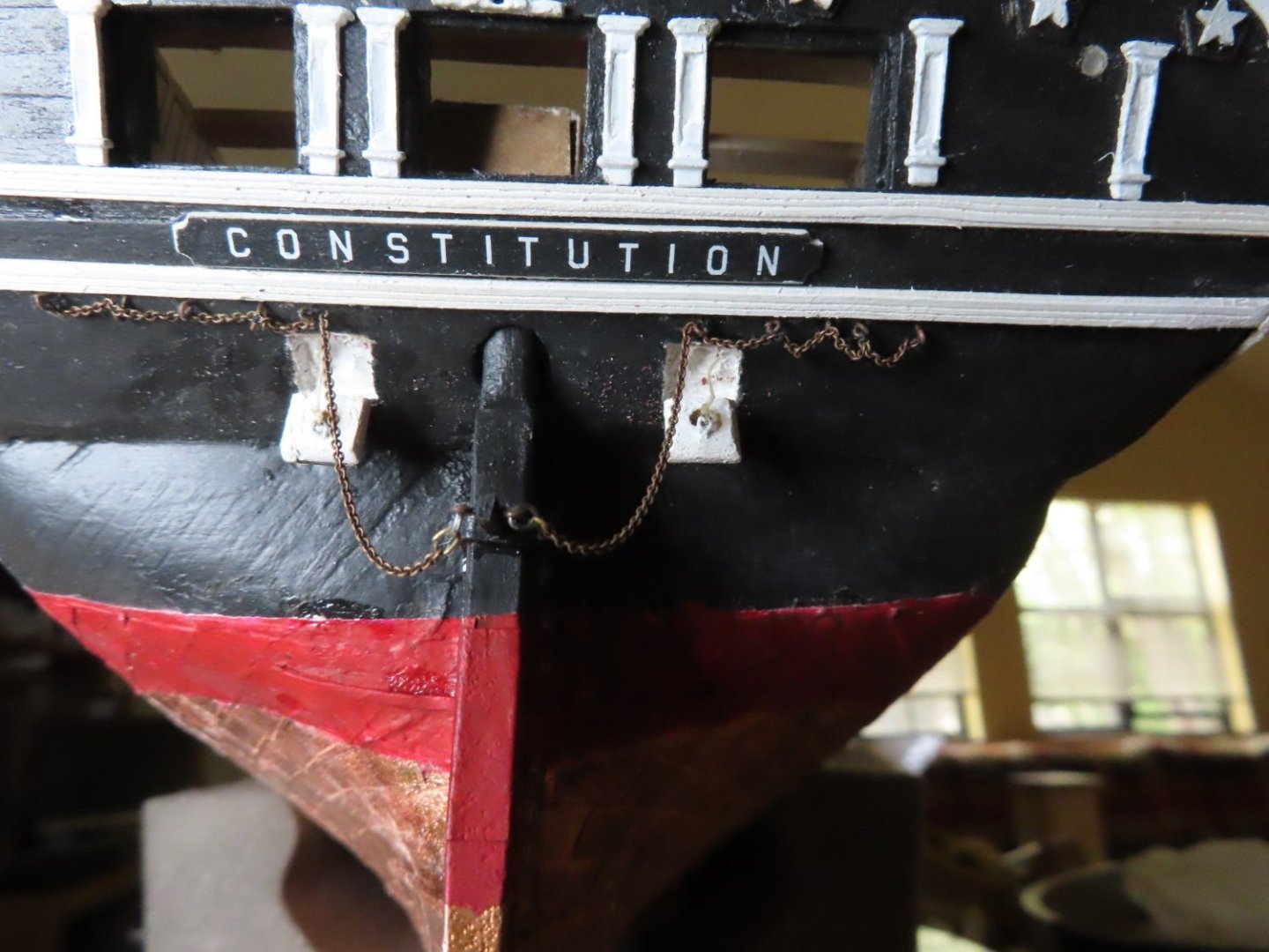
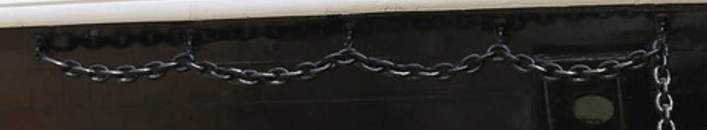
The last connection from the chain was to the anchor iron. I needed to make a link that would be thin enough to pass through the last link in the chain and strong enough for the anchor iron. The photographs show an extra-long link as the last link on the chain connecting to a shackle bolted to the rudder iron. This was how I would make the transition. The long links were made from thin brass wire and the “shackles” were made from a typical staple found in any common stapler. It was a little thicker but would pass through the long link as well as the eyebolt on the rudder iron. A staple is tough, malleable, and easy to manipulate. The components were formed by bending the metal to shape and then blackened. The staple did not blacken very well. But it removed the shine from the metal. The chain and eyebolts were then “simply” inserted into the predrilled holes just under the transom. Well, not so simple. I had to re-drill the holes because my well measured spacing of the eyebolts didn’t match the well measured holes in the hull. If I had to do it over again, I would have added a couple of more links per eyebolt. Finally, the “shackle” was attached to the rudder iron and the long link connected to the shackle,

-
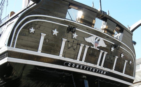
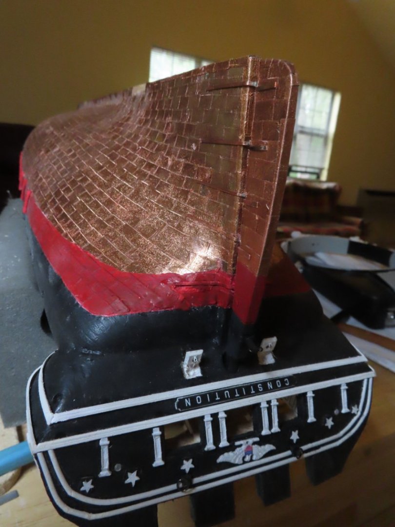
Not to put salt on the wound, but my model looks closer to the actual ship. If you can't move the pilasters, maybe you could make a new smaller eagle. Because of the small scale, maybe just the outline of the eagle might suffice. It could even be made out of white card stock. Jon
- 88 replies
-
- 1
-
-
- Constitution
- billing boats
- (and 1 more)
-
My thoughts on your eagle: As shown, your kit supplied eagle looks over sized at first glance. I checked my model which is 76.8 scale against your model of 100 scale, and noticed that your four most centered pilasters are placed different than mine. A possible solution, not to be take lightly, would be to remove and move those pilasters so they look like mine and then you would have space for the eagle. This is not an easy fix. I don't know what the material those pilasters were made from or how easy/hard it would be to pry them off. Just a thought. Jon
-
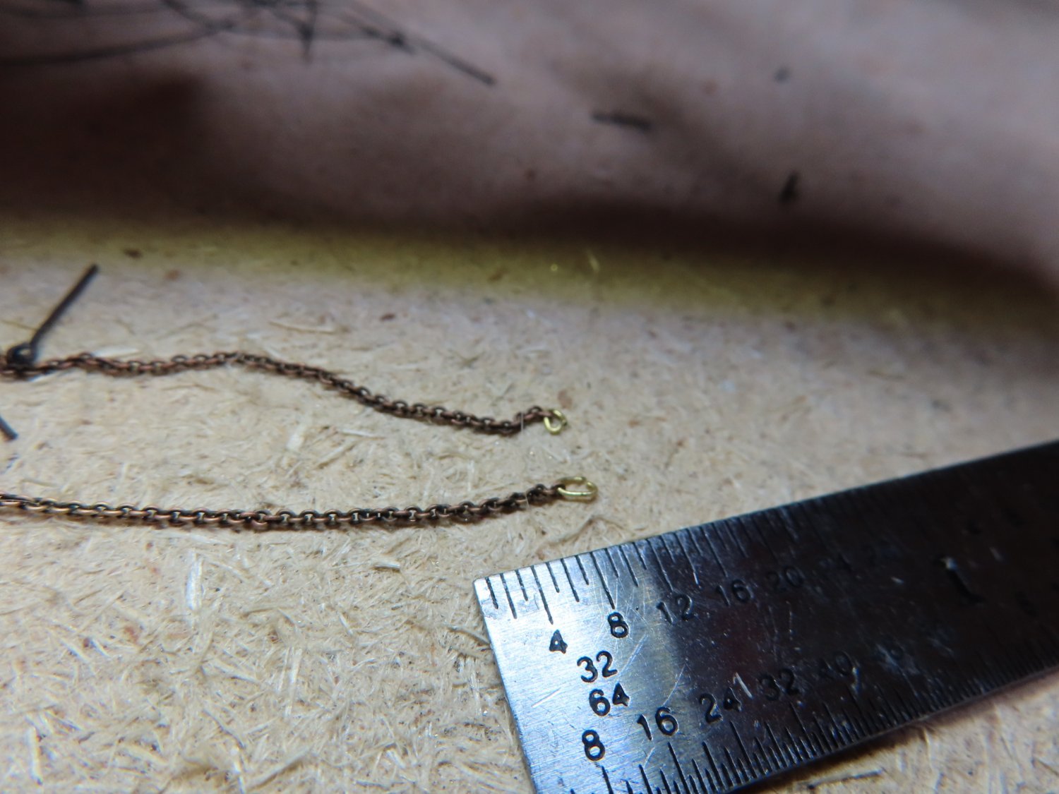
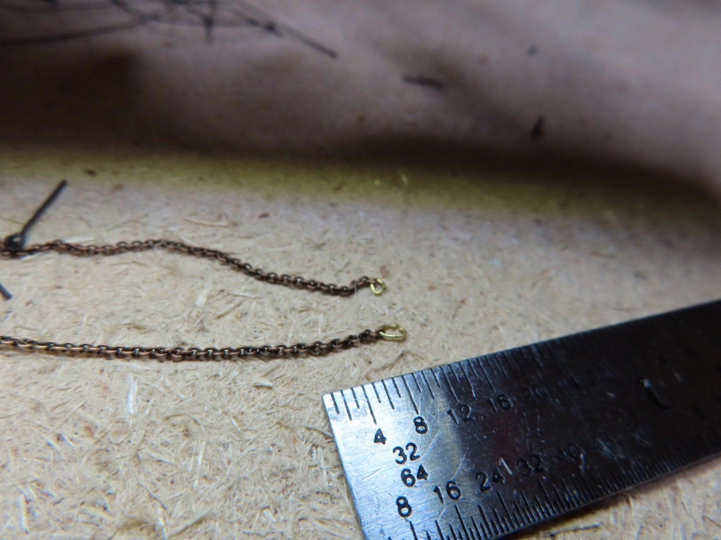
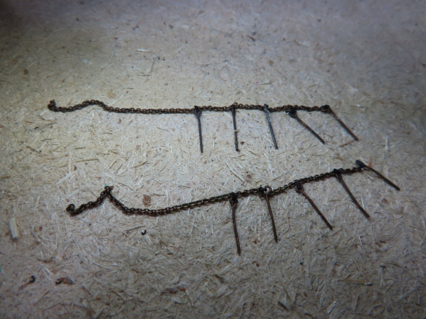
However, I did not like the way the natural hang of the chain was distorted by wrapping the thread around the whole chain. I abandoned Method B and returned to a modified Method A, trying once more to thread through the links. This time, after stiffening the thread with CA glue, the end of the thread was trimmed to a long sharp point using an X-acto knife with a fresh blade. This allowed the thread to poke through the link just enough to be caught by my forceps. Then the thread could be tugged gently and coaxed through the link. The problem was that the fine thread tip was weak and would break easily. Also, any excess CA glue on the thread surface made the thread too thick to be pulled through the link if and when I was lucky enough to get a hold of the protruding thread point. Therefore, the excess glue had to be scrapped off but still leave the thread smooth, pointy, straight, and stiff. This process was learned by trial and error, mostly error, but I managed to get the first one through the links after about a dozen or so tries over a couple of hours. By the time I did the last one, a week had passed but I was able to thread the last link in less than 15 minutes. Once all the eyebolts were attached to the chains, adjusted as needed, and excess thread trimmed, 50 links were counted from the last eyebolt (closest to the rudder), about a 1¼”, and the excess was cut off.
-
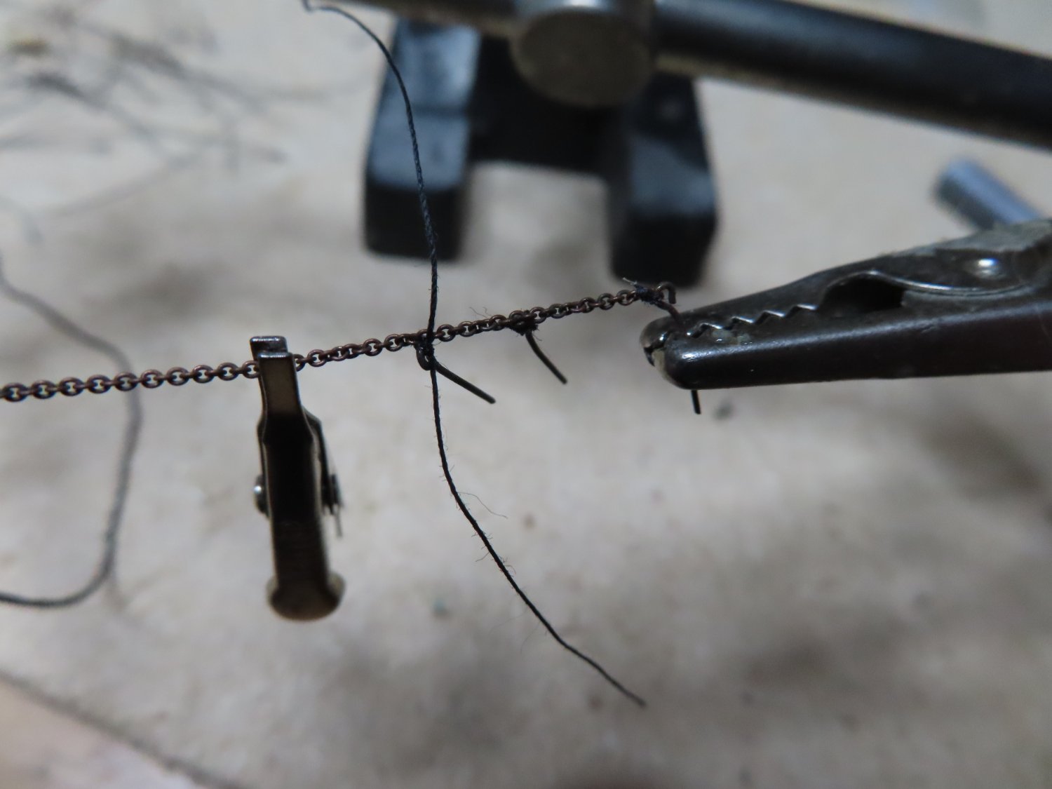
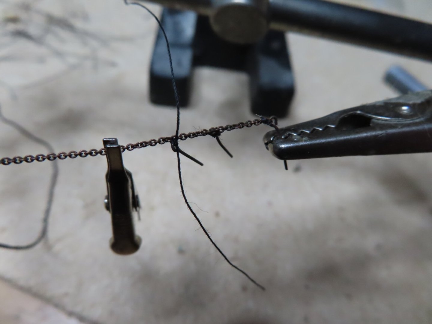
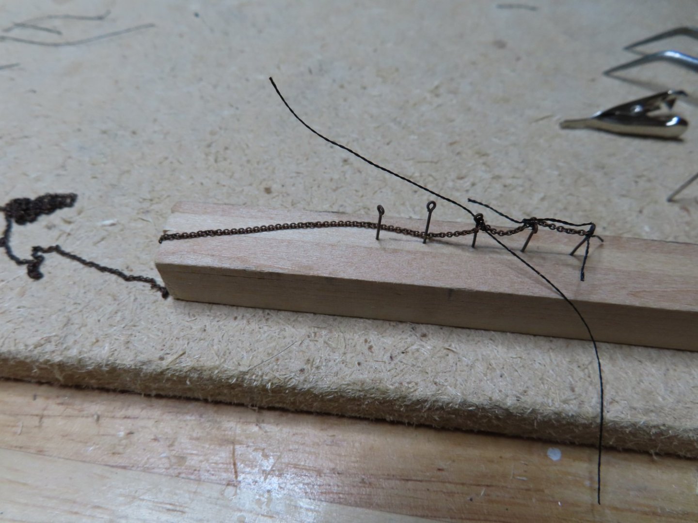
As usual, making something that looks simple… usually isn’t. Attaching the eye bolts to the chain off ship looked easy. Tying the first eyebolt to the end link was. The thread passed through the end link and eyebolt and was tied off with a minuscule drop of CA glue with the point of a needle. The next eye bolt had to tied off about 12 links in from the end of the chain. Try as I might, the thread would (or could) not pass the through a link attached to two other links, even when the thread was stiffened with CA glue. There just wasn’t room enough Therefore I went to Plan B and I connected the second eyebolt by first tying a knot to 2nd eyebolt then wrapping the thread around the chain and tying that off to the eyebolt. The third eyebolt was more difficult to position and tie off because I already had two eyebolts hanging off the chain with excess thread (in case I had to adjust) which caused interference with everything else. After all, the eyebolts were only 9/32“apart. It was at this point I created a simple jig to hold all five of the eyebolts 9/32” apart while I tied the chain to them. Trying to manipulate a tiny chain like that is like holding a wet noodle, it just does not do what you need it to do.
-
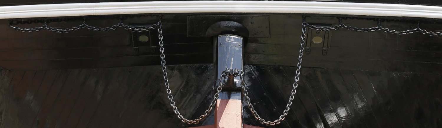
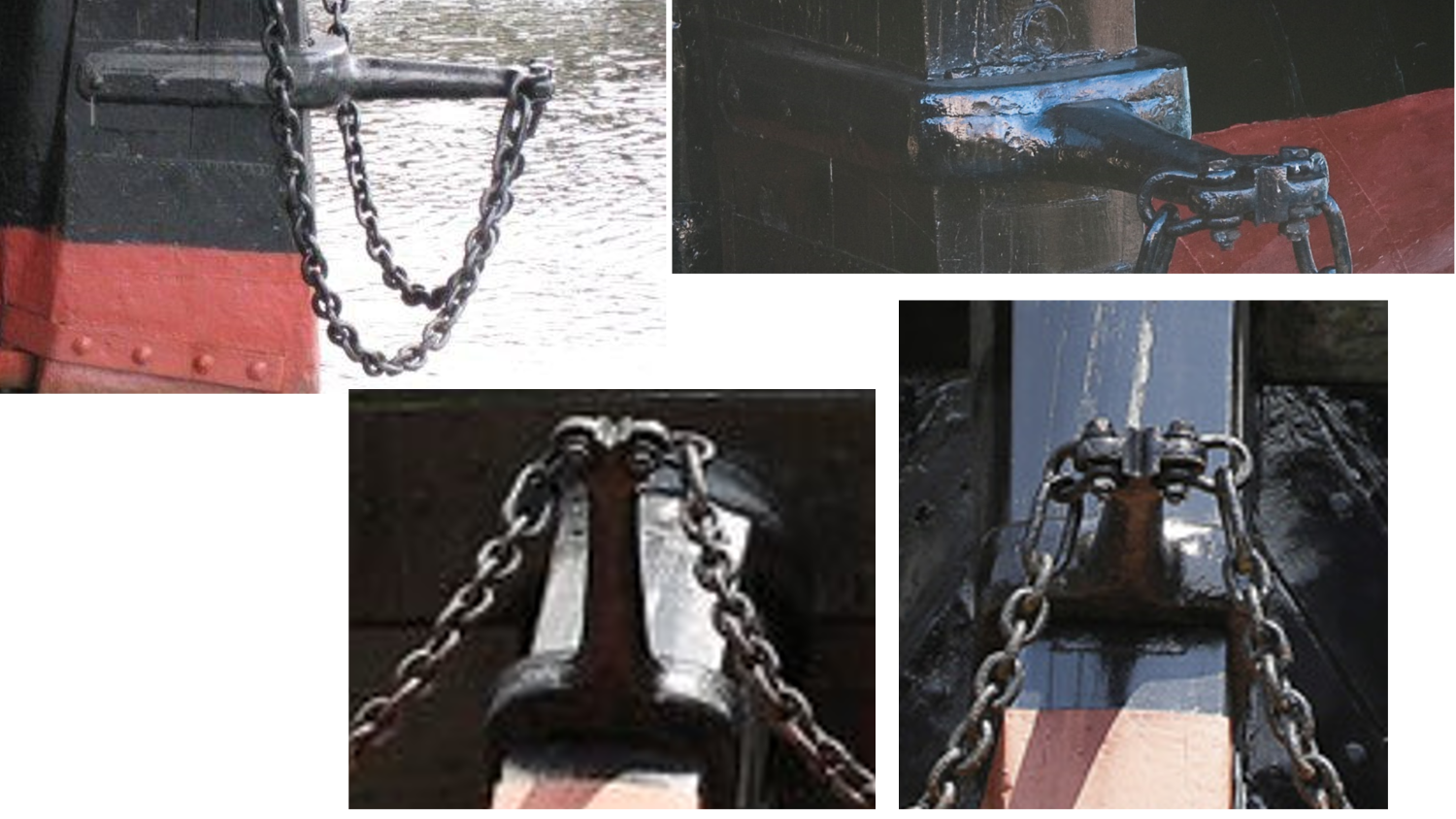
By now, you know that I will attempt to follow the actual ship’s configuration. I counted the actual number of links. As best as I could make out from the photographs, there is a shackle and a long link followed by 50 links from the rudder iron to the first hull eye bolt and then 11 or 12 links between the remaining eye bolts. The kit calls for 40 links/inch chain which is about at scale (based on the link count) and the smallest of the three sizes provided in the kit. Each link is about 1/32” long. The brass kit chain was too bright and shiny, so I used Blacken-It to well, blacken it to match the actual chain. The first problem was to determine how the chain was attached to the hull eyebolts. It certainly did not pass the eye of the hull bolt nor did the eyebolt link to the chain. As near as I could figure out, the chains are hung from each eye bolt with a double twisted hook. I’ve tried to recreate what I think is being used below. This would allow the chain to be removed or hung with relative ease in real life. That being said, at this scale there is no way of reproducing these hooks and even if I could, no one would see them. The simplest and most effect thing to do is to tie the chains to the eye bolts with black thread. It wouldn’t look any different than an actual hook at this scale.

-
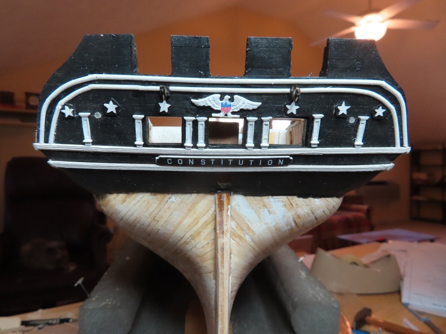
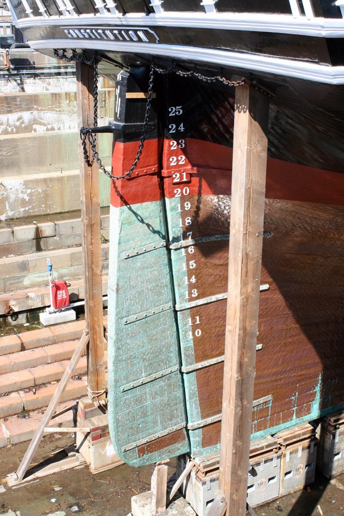
Stern Draught Marks Now that the rudder has been installed, I created the aft draught marks and installed them just like the ones on the stem. I did this now, so that the rudder iron chains won’t get in the way. Rudder Iron Chains I had some preconceived thoughts as to the purpose of the rudder Iron chains, but surprisingly, I found little written about them until I checked one of my books, Ship Model Making Vol. III, How to Make a Model of the U.S. Frigate Constitution, by E. Armitage McCann, 1927. He stated: These chains are quite small and are there to save the rudder, if it comes off or to steer with, if the other steering gear breaks down. It matched my original conjecture. Well, now you know. I felt the practicum didn’t pay enough attention to details of rudder iron chains.: It used out of scale large hull eye bolts. It used four eye bolts per side in lieu of the present day five. (Note: prior to 1927 it had six per side) It had the chains pass through the hull eye bolts’ eye instead of hanging from them. No attempt at measurement of chains length or counting the number of chain links between the eye bolts or to the rudder iron was made. It instructed the builder to paint the chain black after installation on the model

-
You've got some nice billow in those sails. Well done. Jon
- 88 replies
-
- 1
-
-
- Constitution
- billing boats
- (and 1 more)
-
Jeff, just 5 years worth 😁
-
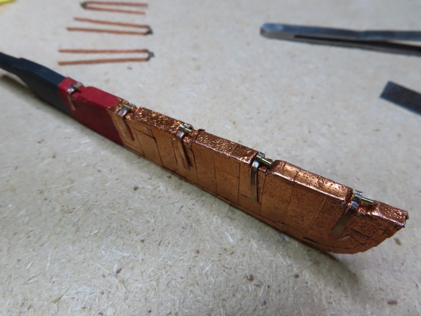
Once I got the first one installed, I tried to install the second. I emphasize the word “tried” because I couldn’t get the two pintles to slip into their respective gudgeons at the same time. Just a thousandth of an inch off in any direction, and they wouldn’t fit. If I did get them to fit, the angle of the whole rudder was off. I must have ripped off these two gudgeons and straps at least a half dozen times or more. However, once I finally got them to fit, the remainder of the strap and gudgeons fell into place relatively easily. I emphasize. “relatively”.
-
Gudgeon Hinges Installation Now it was time to install the straps and gudgeons to the hull. This was not as easy as I thought it would be. The plan was to install the topmost one and then one by one, the next in order using the rudder as my guide. Since I had the model upside down, I was working from the bottom up, but I had a devil of a time. The highest strap (on the bottom) had the most radical bends. I rough shaped the strap bends just to position them onto the hull.
-
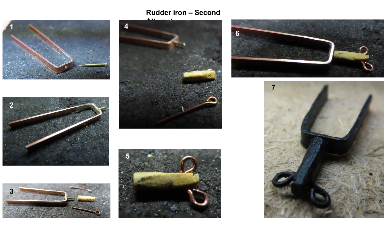
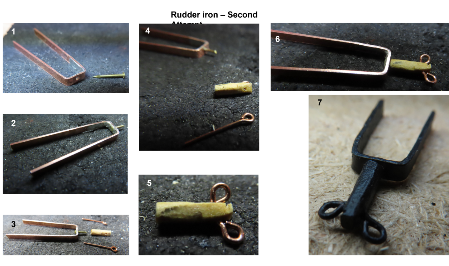
Thinking about this more, even if the joint had held, how do I fasten the rings? If I solder the rings on, I risked unsoldering the nail head (I didn’t have different temperature solders). Gluing with either CA or epoxy was iffy at best due to the miniscule gluing surface areas. I opted for another method. Instead of a metal shaft. I used boxwood. This time I used a small brass head nail. I drilled a hole in the center of the strap and pushed the nail through it from the backside pointing aft. This was silver soldered into place. The shaft was made from a piece of boxwood for strength and ease of shaping the round cross section forward and vertical flat aft. Two holes were drilled on either side of the tail for the eventual ring bolts. An additional hole was drilled at the forward end along the axis to accept the shaft of the soldered nail. Still, the wood piece was very difficult to hold and carve, so I did not get the precise shape I wanted. The CA glued nail will provide a solid connection and structural strength. Finally, the eyebolts were cut to length, and inserted into the aft hole with CA glue. The whole component was painted black, and CA glued into place on the rudder. Using wood in lieu of metal is just fine. It’s painted black and no one will be able to discern the material it’s made of.
-
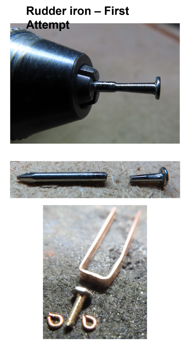
I didn’t like the idea of styrene as it just felt wrong and the final construct, I believed, would be too flimsy to support the rudder chains properly. Other builders merged the straps gripping the rudder together and just extended them to where the rings attached. Some builders used a square cross section brass tube to support the rings. The problem I felt was that the straps had to support an extrusion that extended 90° from the aft end of the rudder beginning with a round cross section and morphing into a flat vertical tail where the two rings are attached. I initially tried to use my limited silver solder skills with a flat head nail. I placed the 1/16” diameter nail in my Dremel to spin like a lathe. With a file, I tapered the nail shaft down a bit away from the nail head using photographs as my guide. Then I cut the tip off the nail leaving the nail head and shaft at the proper length. Using the file again, the aft end was flattened vertically to accept the eventual chain rings. Finally, I silver soldered the nail head to the center of a length of 3/32” wide strip of brass. I had hoped the nail head would give me enough surface area for a strong solid joint. Then I could wrap the length of the brass strip around the back edge of the rudder so the nail shaft would protrude aft. At this point I still hadn’t figured out how to attach the rings. This became a moot point when I tried to wrap the solder part onto the rudder, so I would know how much I had to trim the straps. The soldered joint broke apart and the nail fell off.

-
Rudder Iron (Chain Iron) I decided that before I install the rudder to the yet to be installed hull gudgeon hinges, I better fabricate and install the rudder iron to the rudder while it’s still off the model. On the MS plans it looks similar to a simple tuning fork with a couple rings at the aft end. Looking at photographs, it’s a bit more complicated…of course. The kit does not provide any hardware for this item so it’s a scratch build. Once more the practicum shows how to fabricate it with styrene, while other builders tried other various methods using brass strips and tubes.

-
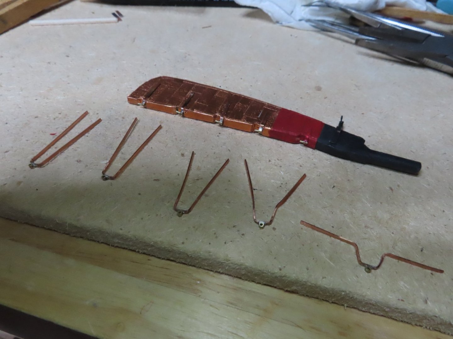
Next, the pintle hinges were positioned and CA glued to the rudder while ensuring there was enough space for the gudgeons to slide under the pintles. The picture below is of the pintles dry fit up.
-
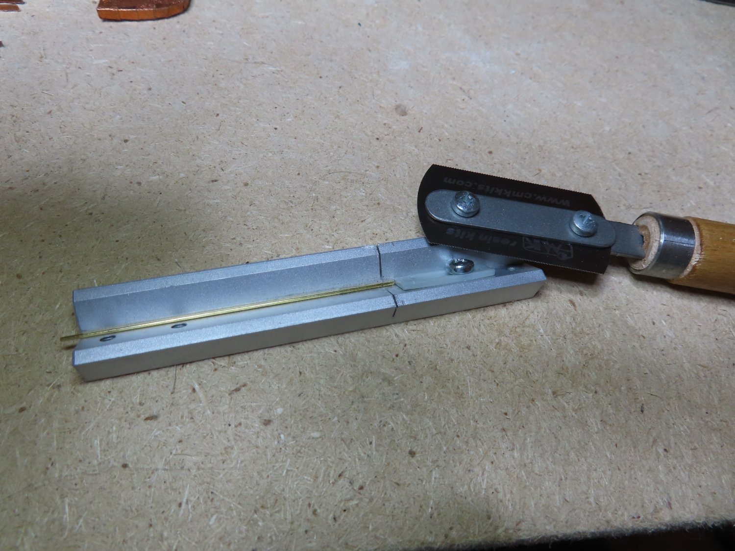
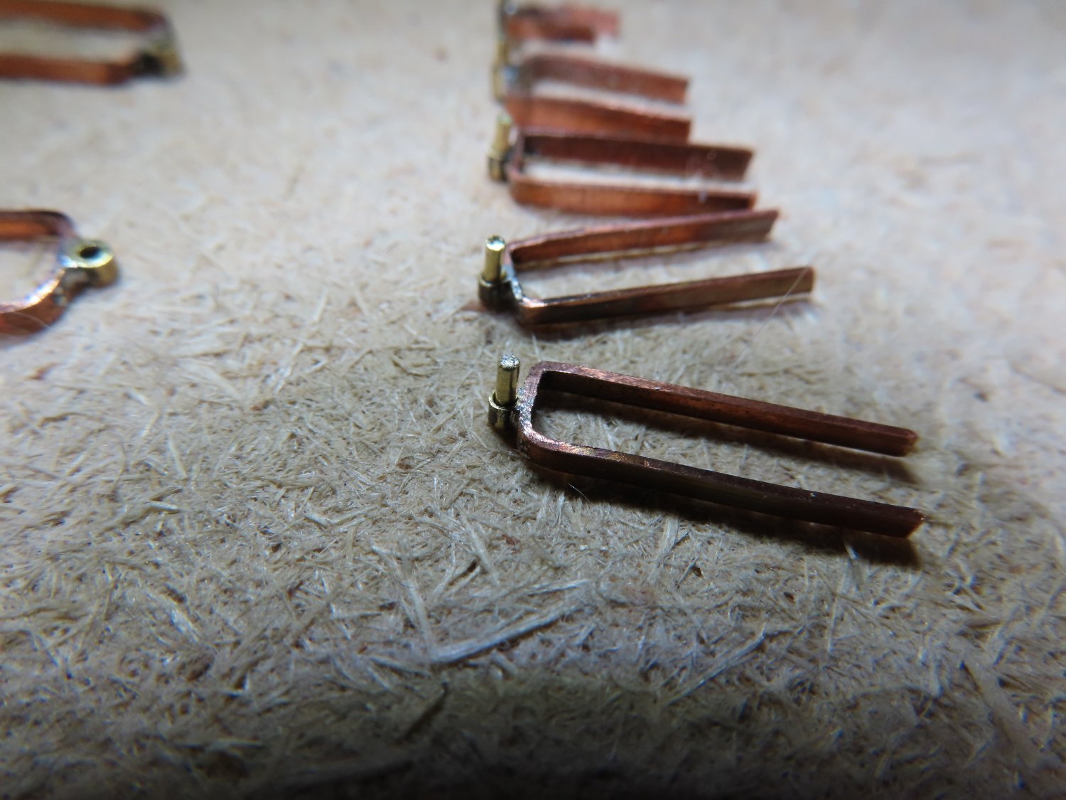
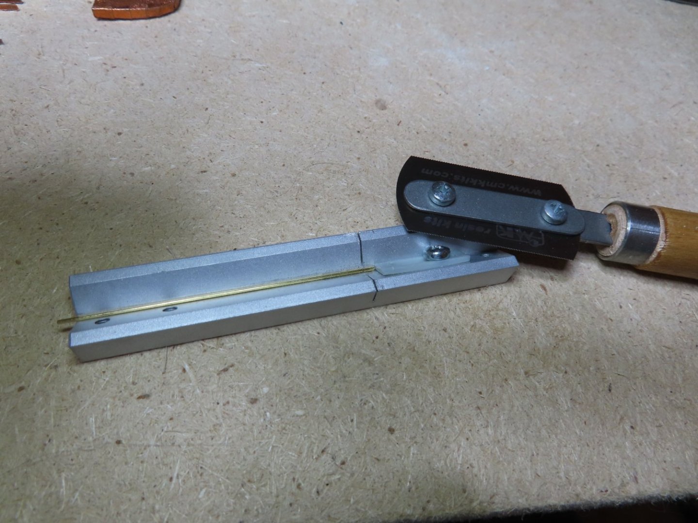
The pintles were fabricated initially as a gudgeon with one extra step. After fabricating the preliminary gudgeons were formed, a length of 1/32” brass rod was sliced into five 1/8” pieces using the razor saw for clean cuts. These 1/8” pieces were inserted into the gudgeons converting them into pintles and fastened with CA glue to complete the process. CA glue was used because it set quickly, was strong, neat, and needed no additional cleanup.

-
Using fine toothed hand saw, the hinges were cut apart. I thought about using my Dremel with a rotary saw or cutting disc, but I realized I couldn’t hold my hand steady enough for a clean cut. A few finishing touches with a file to clean off and smooth the edges, and the hull side hinges and gudgeons were formed.

-
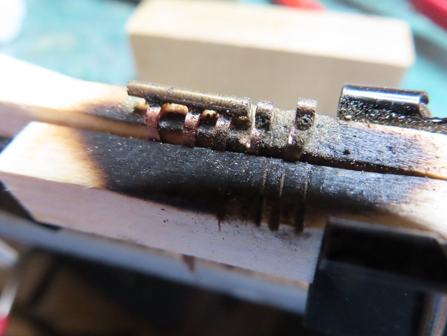
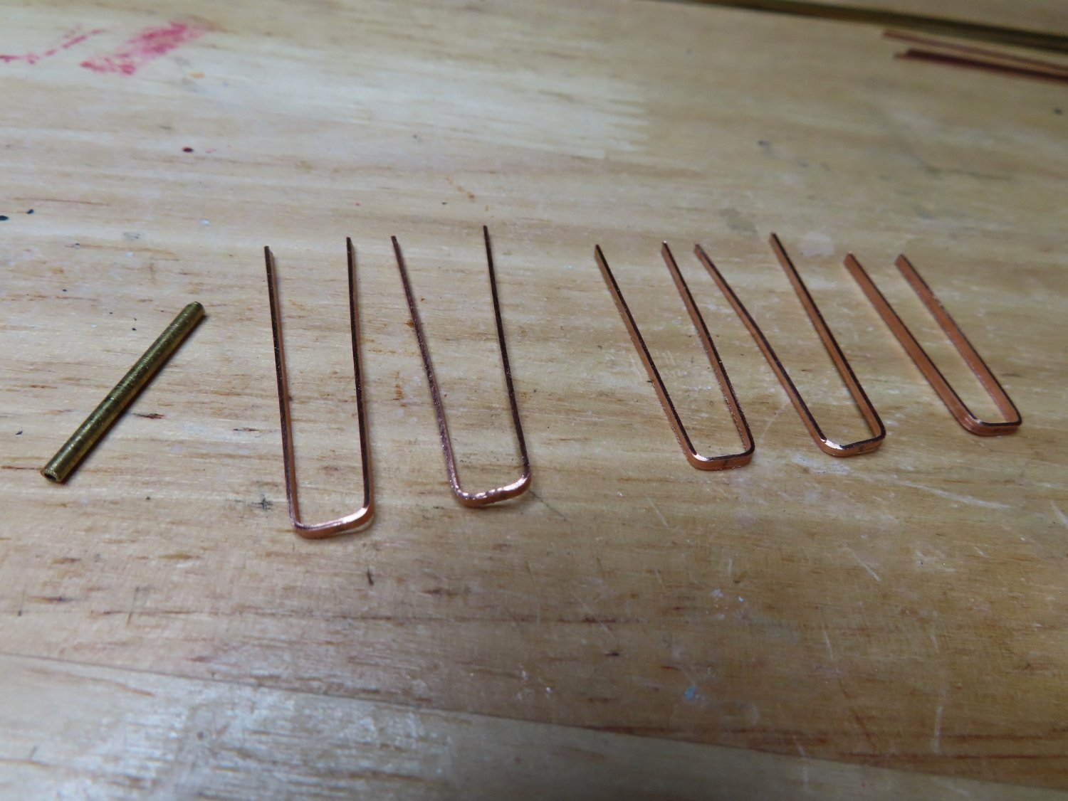
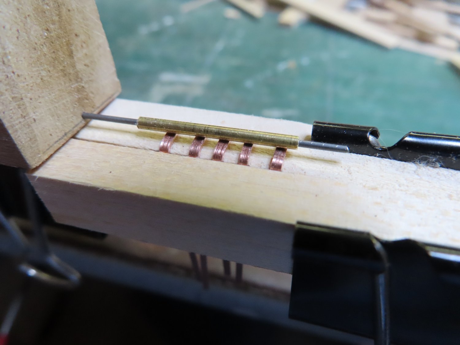
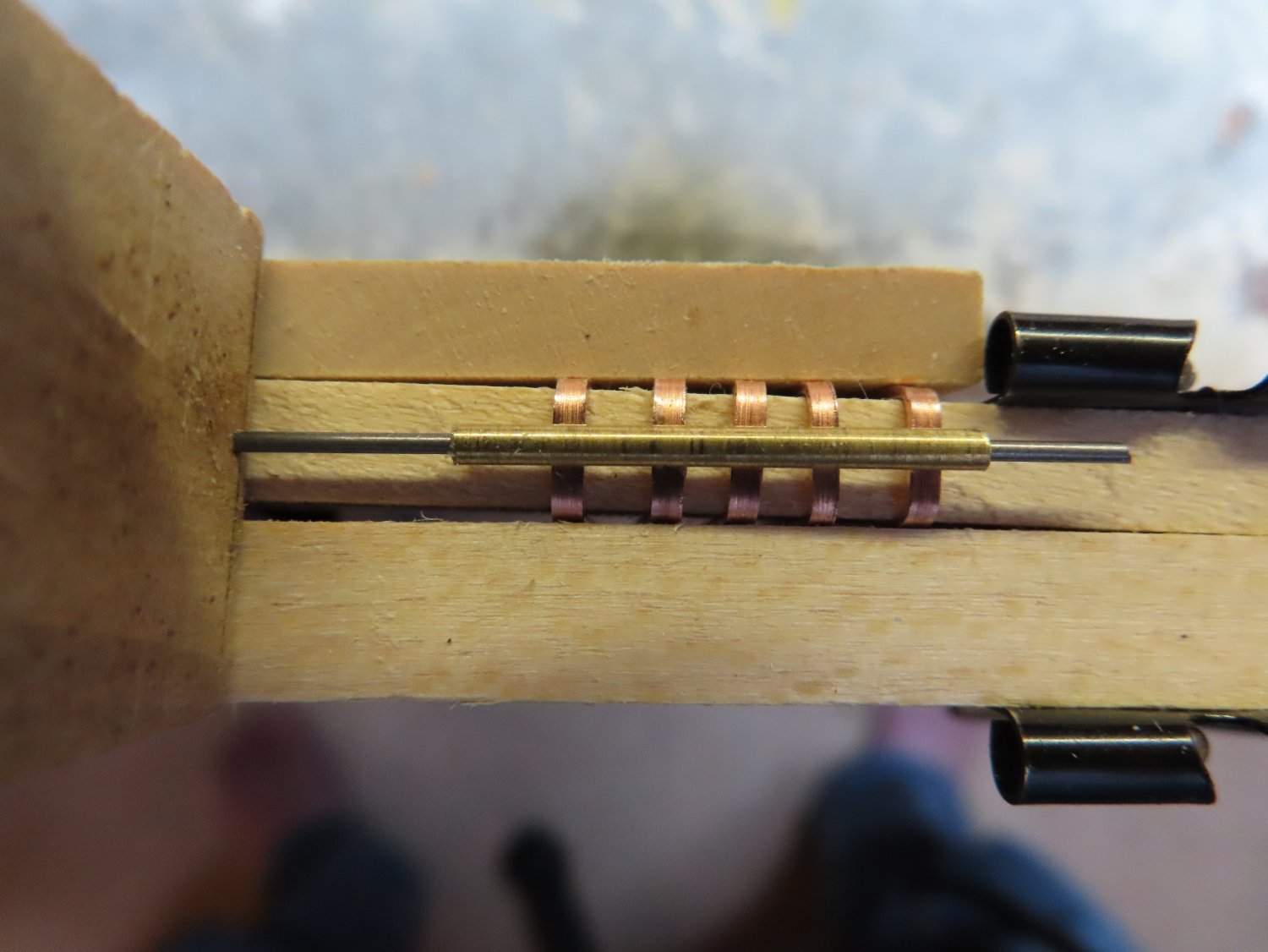
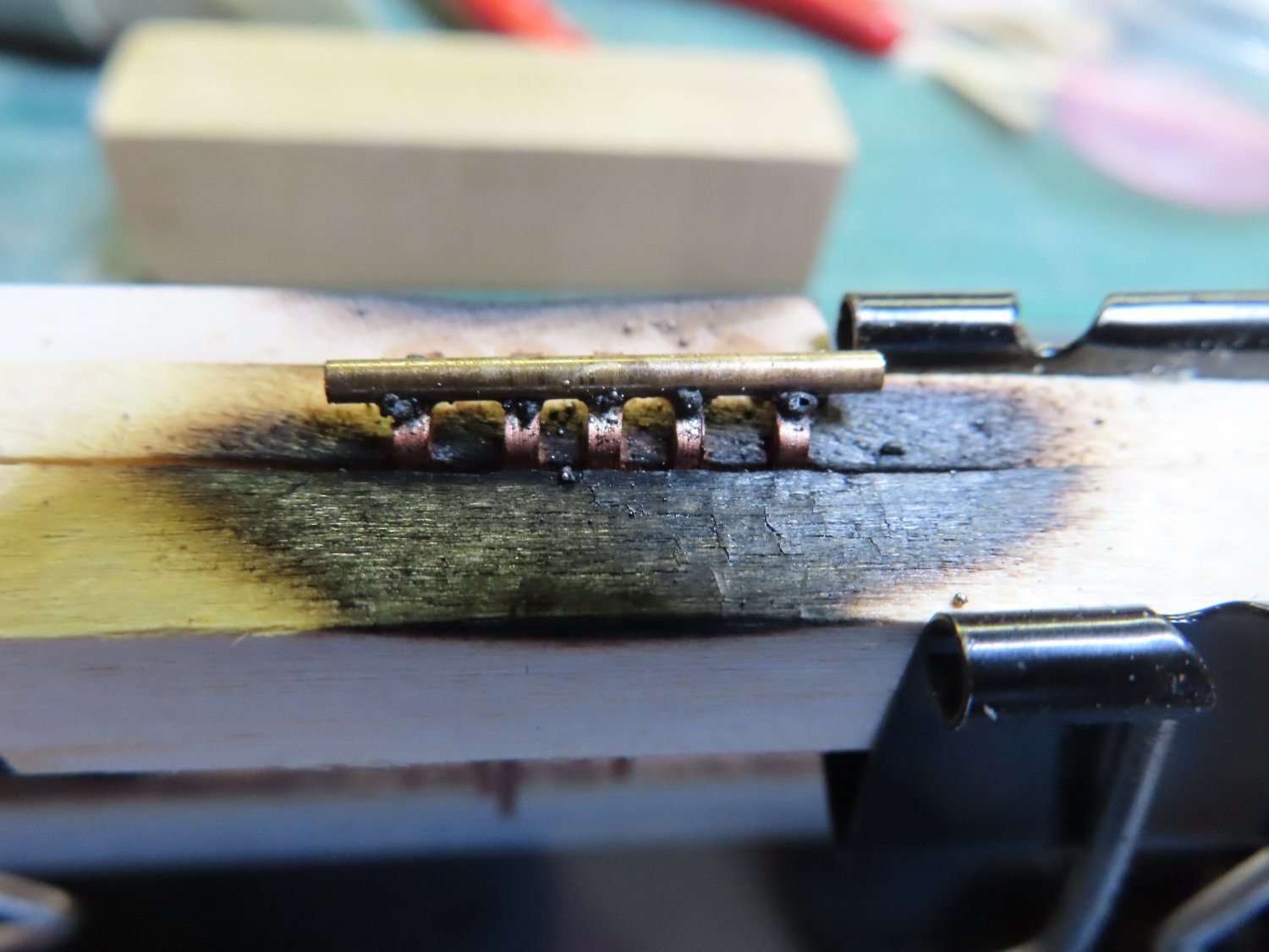
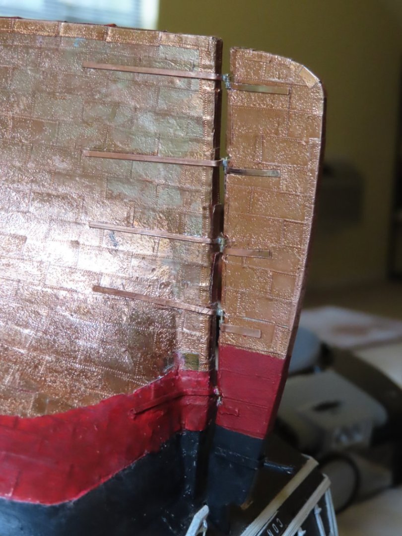
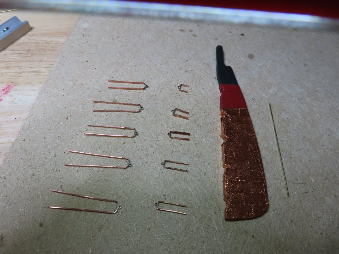
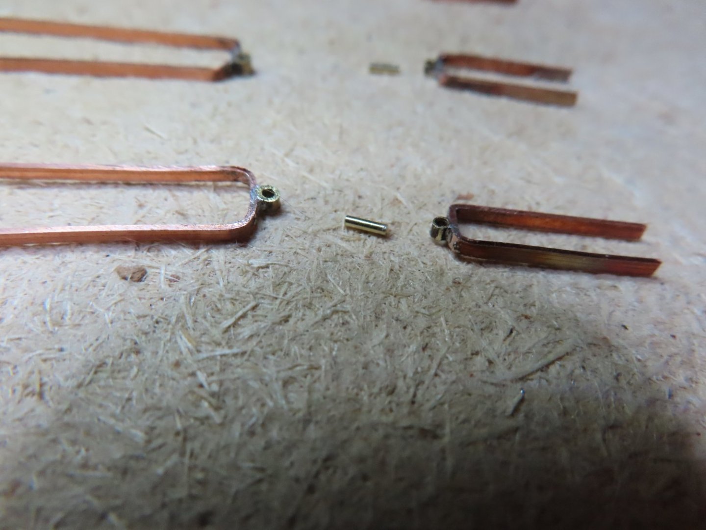
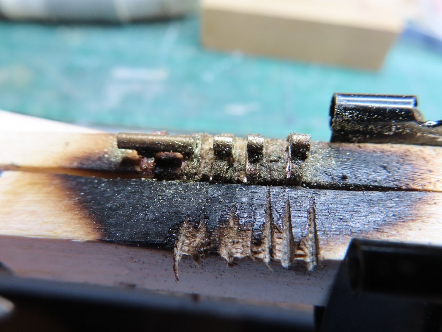
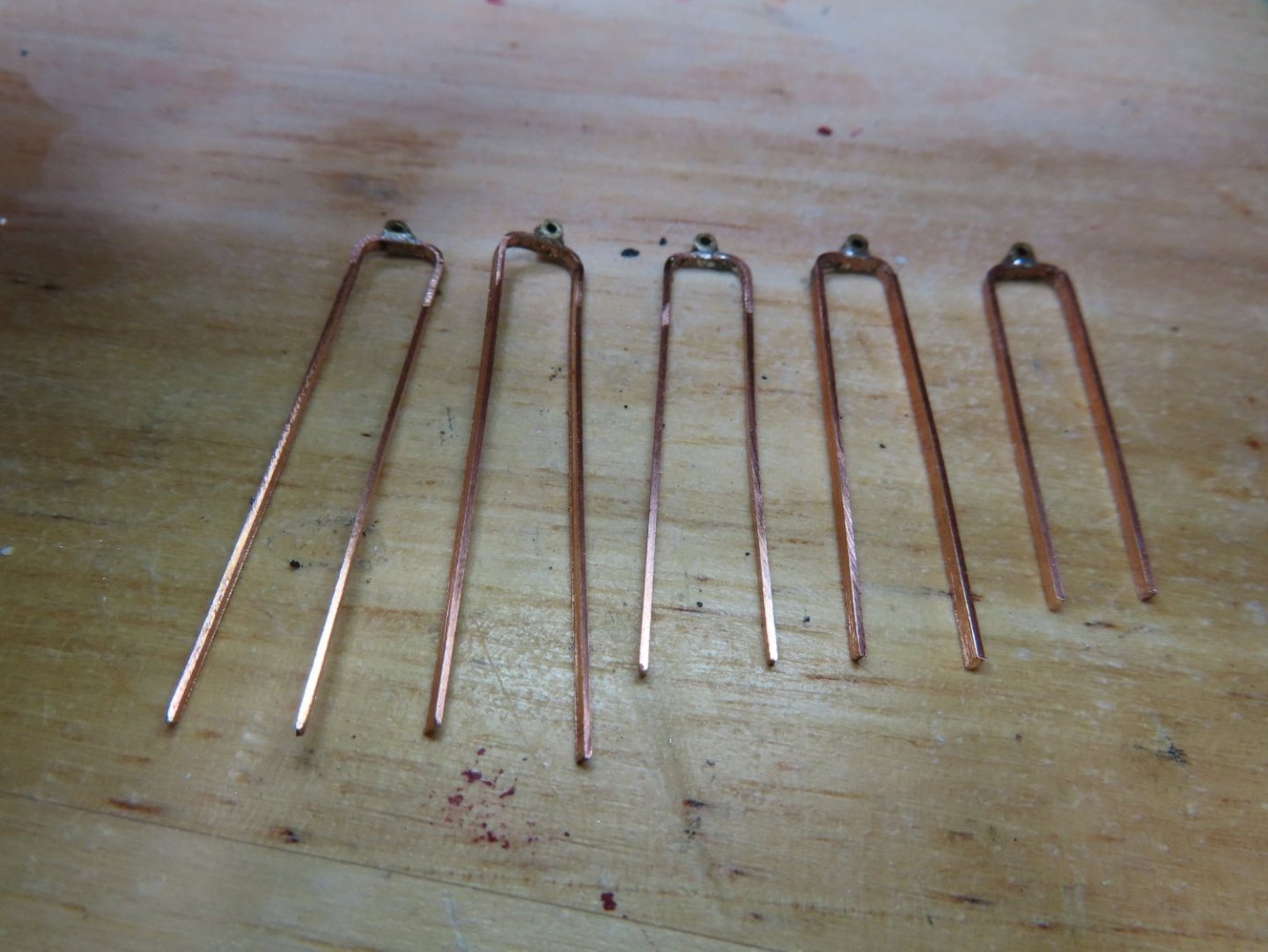
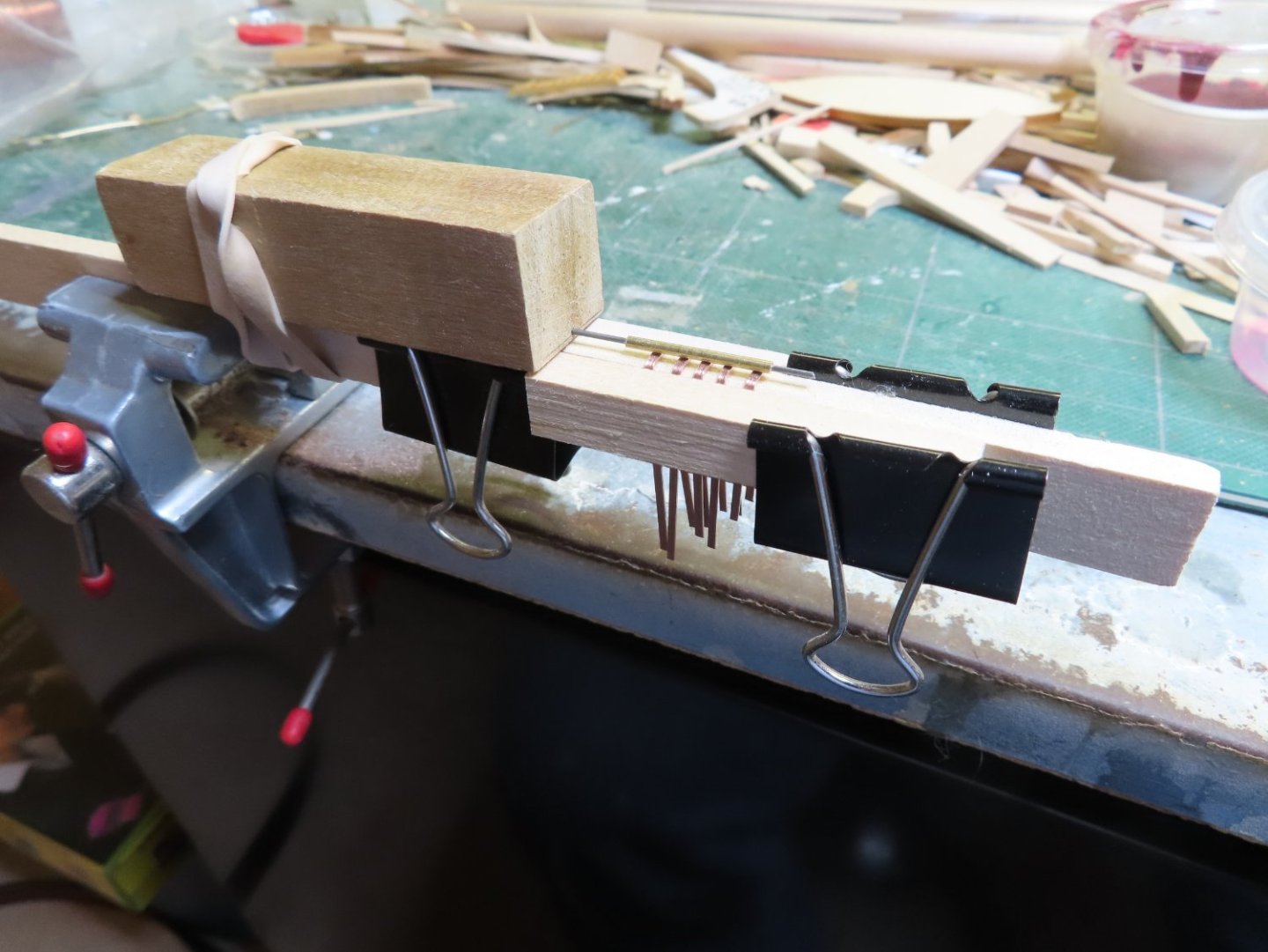
The hull side hinges consisted of two parts, the strap structural element that attached to the hull and the gudgeon. The trick was to form the five gudgeons in perfect alignment so the rudder would be able to pivot smoothly. This was something that Ken Forman made note of. I modified his method so I could not only maintain alignment but made the silver soldering easy. First, I formed the hinges by wrapping the copper strips over a 3/8” thick piece of stock basswood. Then I drilled a 1/32” hole into a piece of wood so a length of 0.032” stiff music wire could be inserted. A length of 1/16” brass tube was slipped over the music wire. The five hinge straps were draped over the same piece of wood that was used to form them and clamped on either side. The block of wood holding the music wire with the brass tube was then held in place over the hinges with a rubber band. When silver soldering paste was dabbed onto each hinge and the brass tube positioned onto the hinges, everything was in place. With a couple of passes with a small torch, the tube was soldered to all five hinges assuring the gudgeons would be perfectly aligned.


-
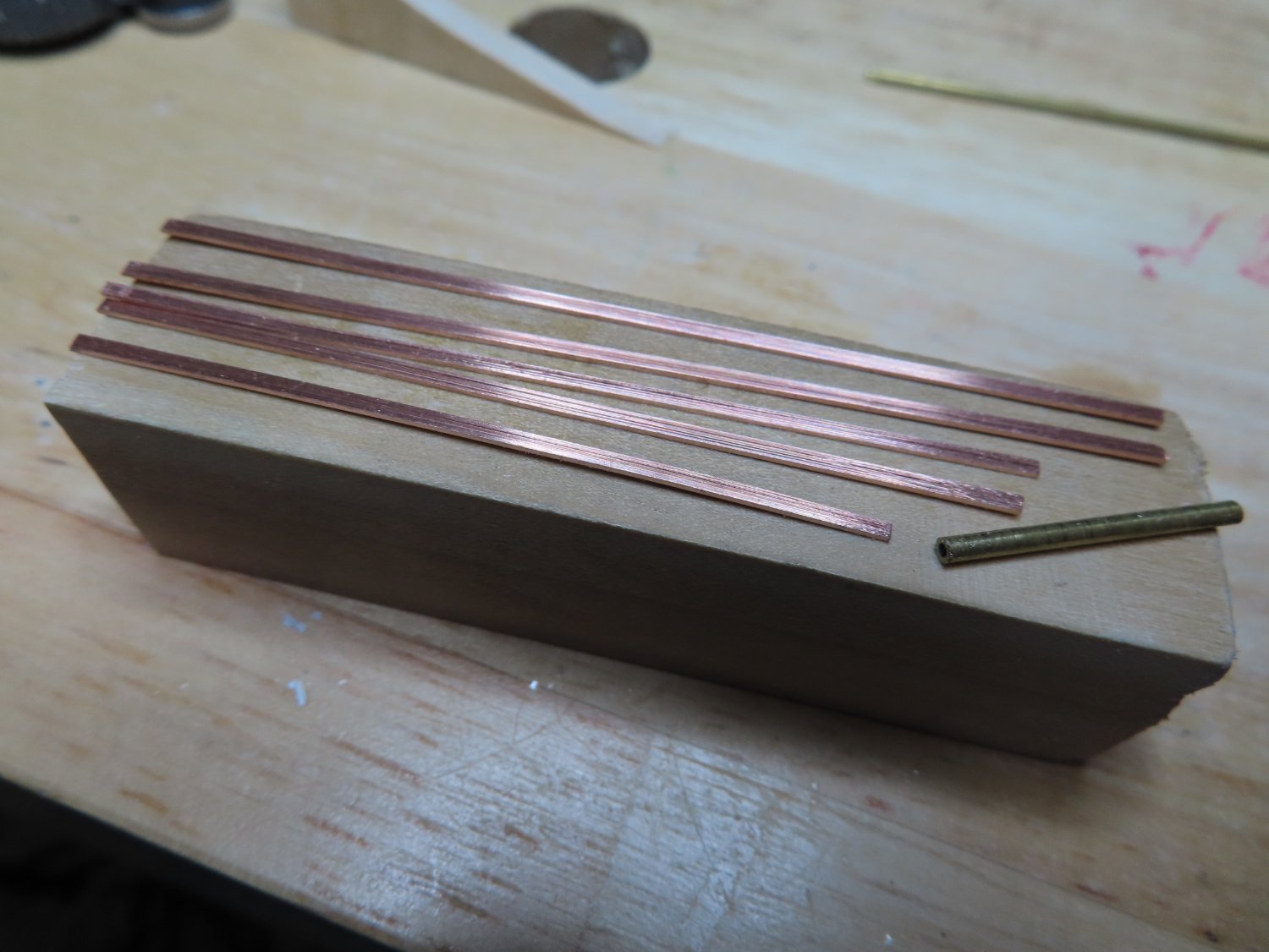
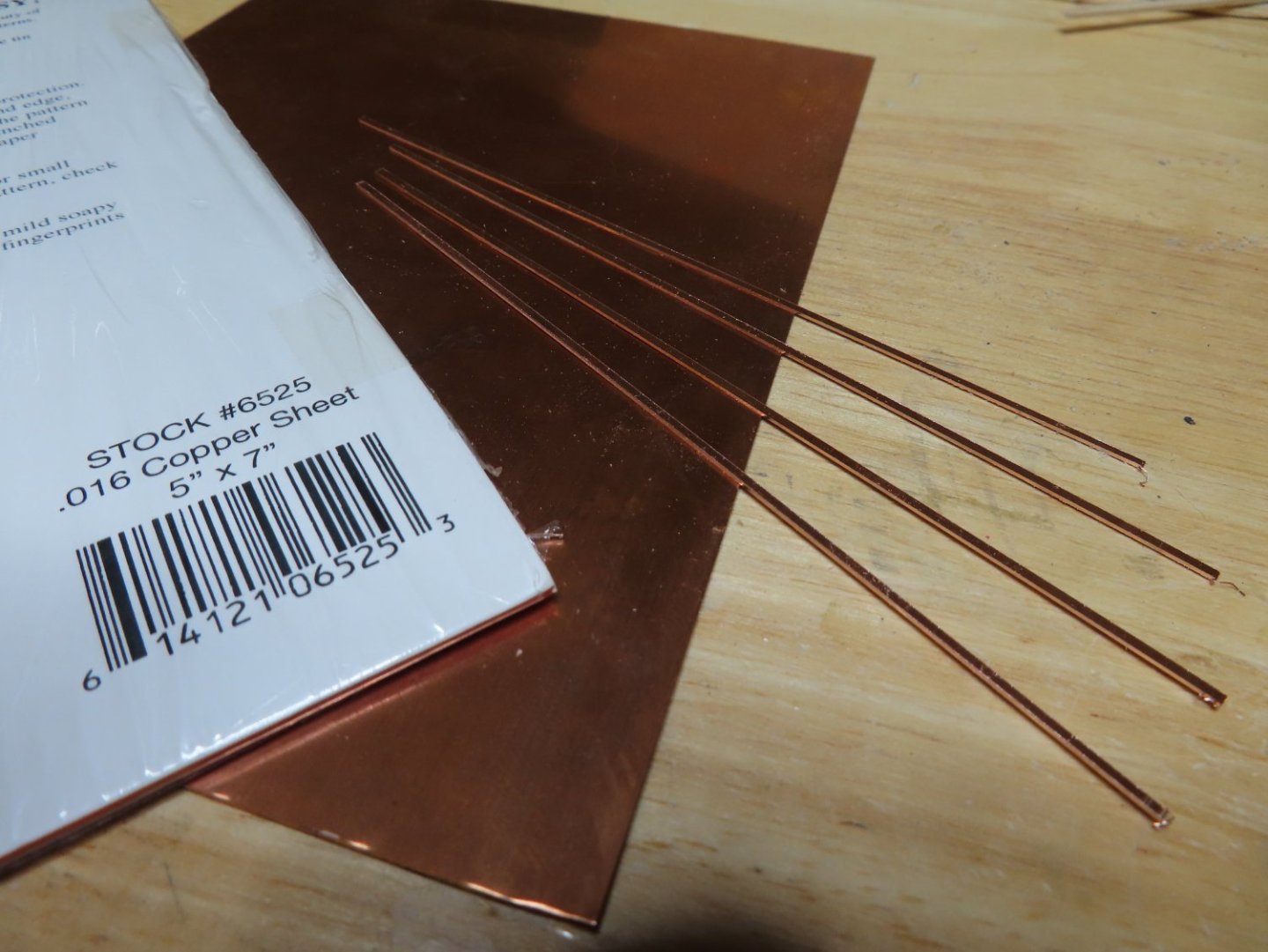
I used my Byrne’s saw with a fine-tooth blade to slice the 1/32” strips of copper from the sheet without any problem. The strips were cut to length. Some builders attempted to simulate the hinge fastening bolts, but I decided, as much as I wanted to, to forego the attempt as the final product would most likely be out of scale or be too small to matter at 1/76.8 scale and not worth the effort, less than 1/128” in diameter or about 1/3 the width on the hinge.

-
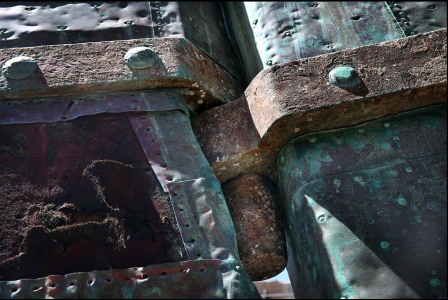
I had to do some thinking about how to fabricate the rudder hinges. Robert Hunt’s practicum opted to make a non-functioning rudder using styrene as the build material of choice. Looking at Ken Forman’s (xKen) build log (my go to alternative guidance), he created functioning rudder using brass which I liked. Both builders painted their hinges black. Others who used brass, sometimes left their hinges as bare shiny metal. However, looking at the pictures of the actual rudder, I noticed the color of the hinges matched the background colors of the green patina of the copper plate, the red waterline, and black painted hull. Does that mean the green hinges are made of copper? More than likely they were made of iron but were colored by the bleeding patina of the copper plates. For my model to have the same color of the copper plates as it ages, my hinges were made from 0.016” copper sheet. Remember, it’s a model, not a miniature replica.
-
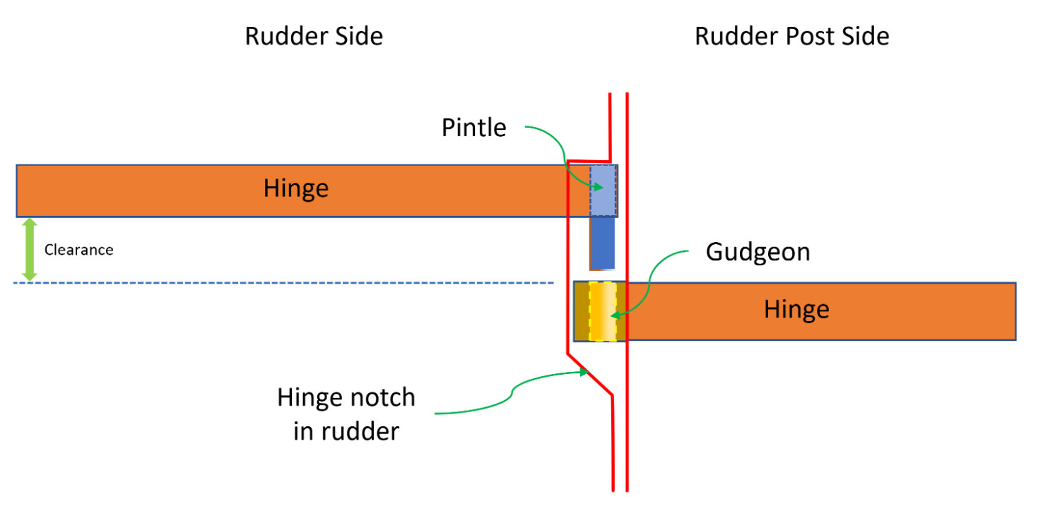
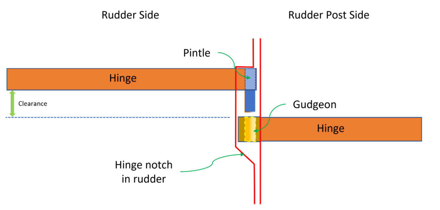
Rudder Hinges For a simple mechanism, the hinges will require a high degree of precision to allow the rudder to pivot effortlessly. All the hinge parts must line up precisely or the rudder will bind. Also, the rudder must be able to move vertically to provide sufficient clearance space for the pintles to move into position to drop down into the gudgeons.
-
As part of your research, here is what I did and strongly suggest you do as well: Download all of the US Navy Plans from the USS Constitution Museum website as a supplement to the kit plans. They have been invaluable in my build. Download as many pertinent photos of the actual ship from the web as you can. Anything that shows details of the stuff you are going to model. I personally have and cataloged about 3,700 images. If you can't find something, just ask, there is a good chance I may have it. (if you have any interesting ship photos that you would like to share, I'd be willing to accept them). Study other build logs of the USS Constitution to see how they handled the variety of tasks/problems they encountered during their build. I've actually copied those logs and so I can access them offline. Sometimes stuff just disappears from the web. You can learn an awful lot of useful stuff from other people successes and mistakes. Get access to reference material about the USS Constitution, building techniques (model and actual), etc. Visit the actual ship which you've already done and likely will do again. I grew up in the Boston area and visited the ship about 4 or 5 times over the years, so I have a personal affection with the ship. My last visit was just before her last restoration in November 2014. I'll give you my 2 cents worth of wisdom (such as it is), just ask. Good luck on your build. Jon