Piet
-
Posts
3,568 -
Joined
-
Last visited
Content Type
Profiles
Forums
Gallery
Events
Everything posted by Piet
-
 Wow Boris, that looks really good! I like the detail with the had-holds along the con and the periscope holder. Cheers,
 -
Thanks to everyone for visiting and liking my work, it's appreciated. @ Adriaan, you are quite welcome my friend and I hope you can make use of the idea. @ John (Lad), yup, I have heard and read this as well. According to what Gino den Ridder told me the O 19 and O 20 being mine laying subs, would operate in coastal waters to block shipping lanes at strategic places. The Navy thought to paint these two subs as described to blend in with the background. I really have very definitive knowledge on all the paint schemes the world's navies employed. It would be an interesting research project though, if I had the time Cheers,
-
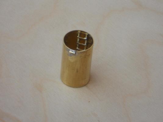
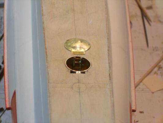
Thanks again to all yuns who visited my shipyard and clicked on "like." Today was very productive and fun. First thing I did was searching for my mast / spar sanding jig but gave up. I decided to make a new one and post a "how to" to Adriaan's (Andrieke) King of the Mississippi log because he had trouble with breaking his and so did Robbyn. No problem, it was all done in an hour, with the help of the Admiral Gwen. After lunch I posted everything on Andrieke's log and was asked by Mark T. to also post it in the how to section of the Forum. I know that there are other ways to do this but this is a quick, easy and above all, a cheap way. What else can you expect from a Dutchman, eh? That gave me some time to finish making the ladder for the forward crew escape hatch tube and the hinges. This was accomplished before lunch and I could now temporarily put this in place inside the deck structure. Once this assembly is permanently cemented in place there is no way to remove the hinge pin, so I must be sure that everything fits and works. That'll be for Sunday to determine and for making the final adjustments. then it's on to the other escape tubes. I made a jig to hold all the parts and pieces together to make the ladder. The clamp doesn't only hold everything down but acts as a heat-sink. I had to spend some time cleaning off the excess solder. This shows the ladder installed and tack-soldered to the bottom of the tube. Out of sight out of mind I also soldered the center hinge on for the domed door. Prior to attaching it to the tube I filed the round rungs flat for a better and natural appearance Here is the tube assembly out in place temporarily with the domed door standing by. I modified my oak die to give it a more prominent dome. Obviously the edges will shrink and i have to cut a slit into it before putting de die and brass piece in the vise. This will be covered with a small strip of brass that will also have the outside hinge tubes soldered to it. I don't know yet how i'm going to tackle the large domed doors for the AA gun tubes. In the meantime i cut two small sections of brass tube for the door hinges and soldered them on. Had to use a heat-sink there as well but it all worked out okay. here is the entire assembly put together and temporarily put in place in the deck structure. I forgot to take a pic with the door closed but it looks real good. I think I'll paint the inside of the tube a light grey. The bottom of the hole will be flat black. This is a shot from another angle, looking aft. You are probably wondering what that circular mark is for? Glad you asked. That's where the future ventilation outlet will be. It's for exhausting inside stale and hot air to the outside while on the surface through a high capacity electric fan. I'm not sure yet whether it's in the center of a little towards port. Cheers,


-
Hello Mark, Yes, will do. I can copy - past this entire section. It'll be tomorrow evening though before I get to it. Cheers,
- 1,038 replies
-
- 1
-

-
- King of the Mississippi
- Artesania Latina
- (and 1 more)
-
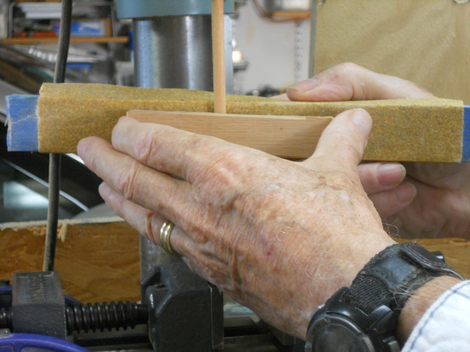
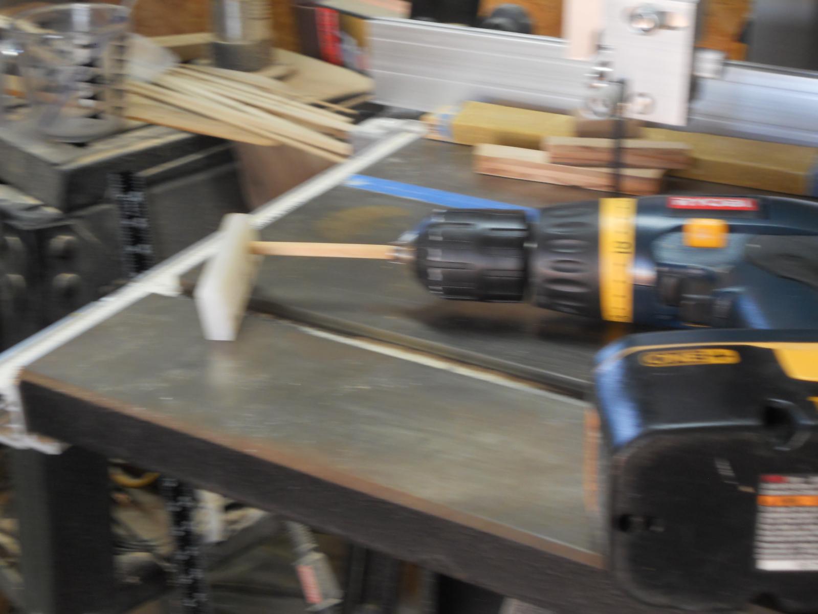
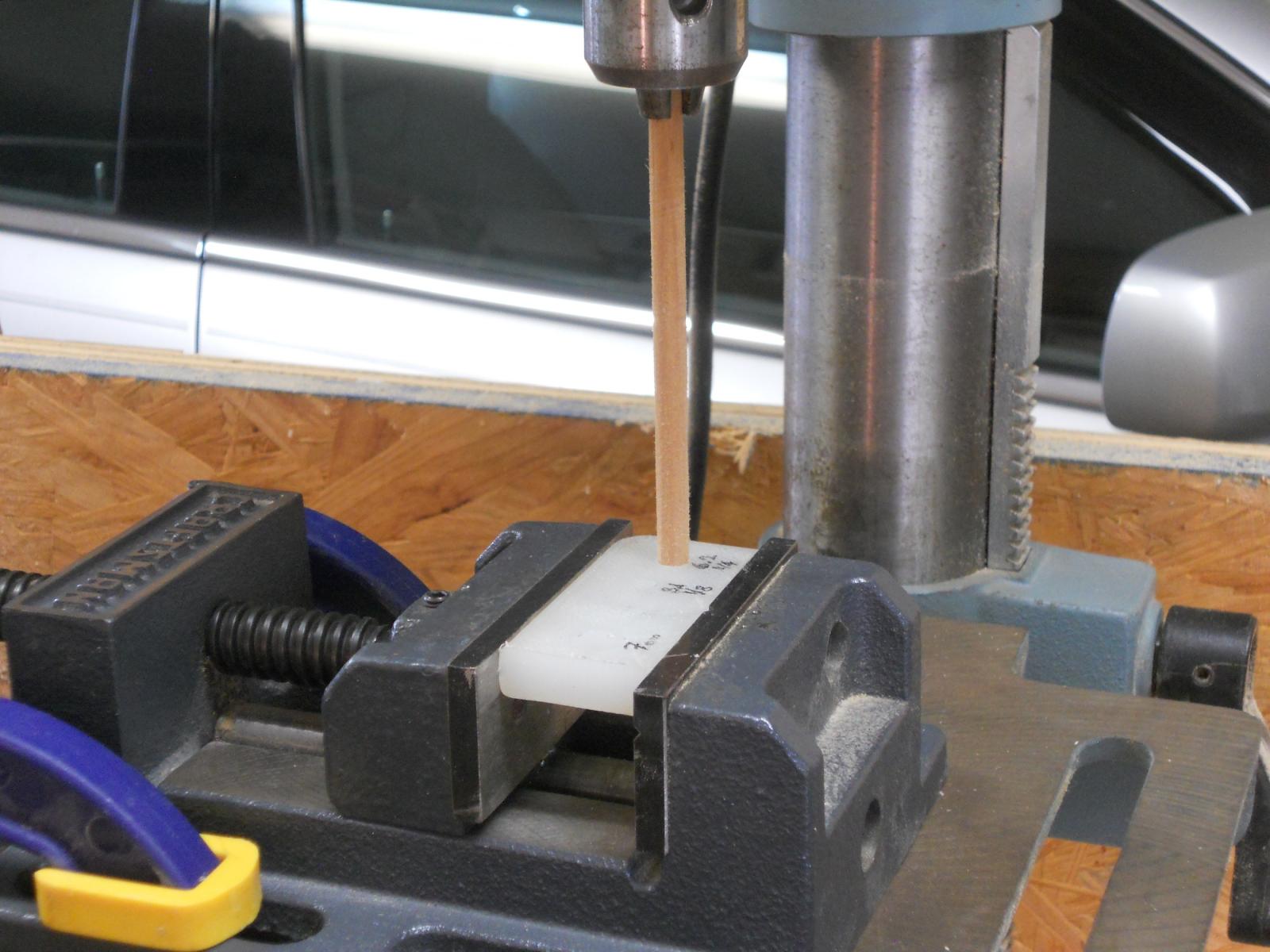
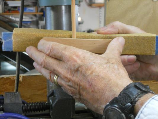
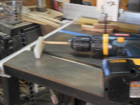
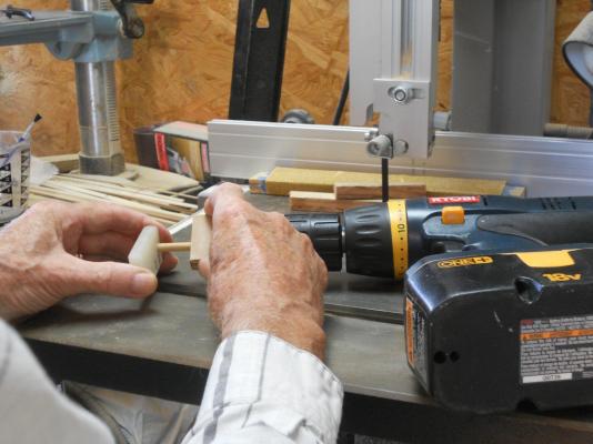
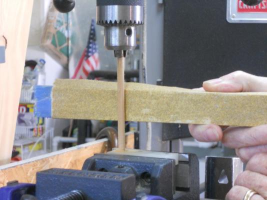
Continuation of mast / spar sanding jig. I am using the larger sanding block with course sandpaper and one handed too All the way on the right bottom of the pic you can just make out one of the clamps I used to secure the vice to the drill press table. This way we can use one hand for the sanding. Don't use too much pressure on the dowel, especially when sanding thin dowels. Also, the speed should not be too high, there is no need for that. Let the sandpaper do the work - - - gently, take your time and use a dust mask!! When you approach the end of your spar, which is now very thin you'll have to switch over to fine sandpaper and finish it off. Frequent measuring in between is also advisable, this also gives the wood and the nylon a chance to cool down some. You can now also cut off the thicker portion of the dowel that's inside the nylon thingy and drill or use a small hole to continue or use the hand-held method shown further down. All of this may take some getting used to but after a few you'll get the hang of it. You can also use a a piece of sandpaper hand-held between fingers and thumb, if you dare of course A demo in using the small sanding block for the finishing touch but hand-held sanding works also. For demo purposes I am now not using the nylon jig thingy but when you do this you MUST back-up the sanding block with a piece of hardwood. If you don't your dowel will brake at the drill chuck. And again, don't use much pressure on the dowel when sanding. I found that making a groove in the back-up block helps in keeping the dowel centered to the drill chuck. Here hand-held sanding works really well but it gets pretty warm though, you'll quickly find that you'll have to easy off in between applying pressure. I apologize for the fuzzy pic, I moved my hand but you get the idea. I am showing a hand-held method with a portable drill motor. I didn't show it clamped here but you understand that you MUST secure your drill motor. Set the drill motor speed to medium, not too fast and not too slow. Before we switch on the drill motor with a preset speed, we slide the nylon thingy onto the dowel and position your hand FIRMLY to the table or board and switch on the drill motor. You may be apprehensive or afraid in doing this but believe me, the dowel will automatically seek equilibrium and directs your hand to center itself. Now with your free hand you can gently use your favorite sanding block and let the dust fly with a dust mask on, please. The whole purpose is to support your dowel at the opposite end from your drill motor or drill press. When taper sanding small spars, where the ends are very small, like 1 mm perhaps, you may have to drill a small hole in the nylon thingy to support that small end. After a while of doing this you'll get the hang of it and produce spars by the dozen Hmmmm, maybe I'll go into business making spars - - - not I hope this method works well for you as it did for me. Now I better put that small nylon jig thingy in a safe place where I can find it because I have a bunch of spars to make for my neglected VOC ship. Cheers,

- 1,038 replies
-
- 4
-
-
- King of the Mississippi
- Artesania Latina
- (and 1 more)
-
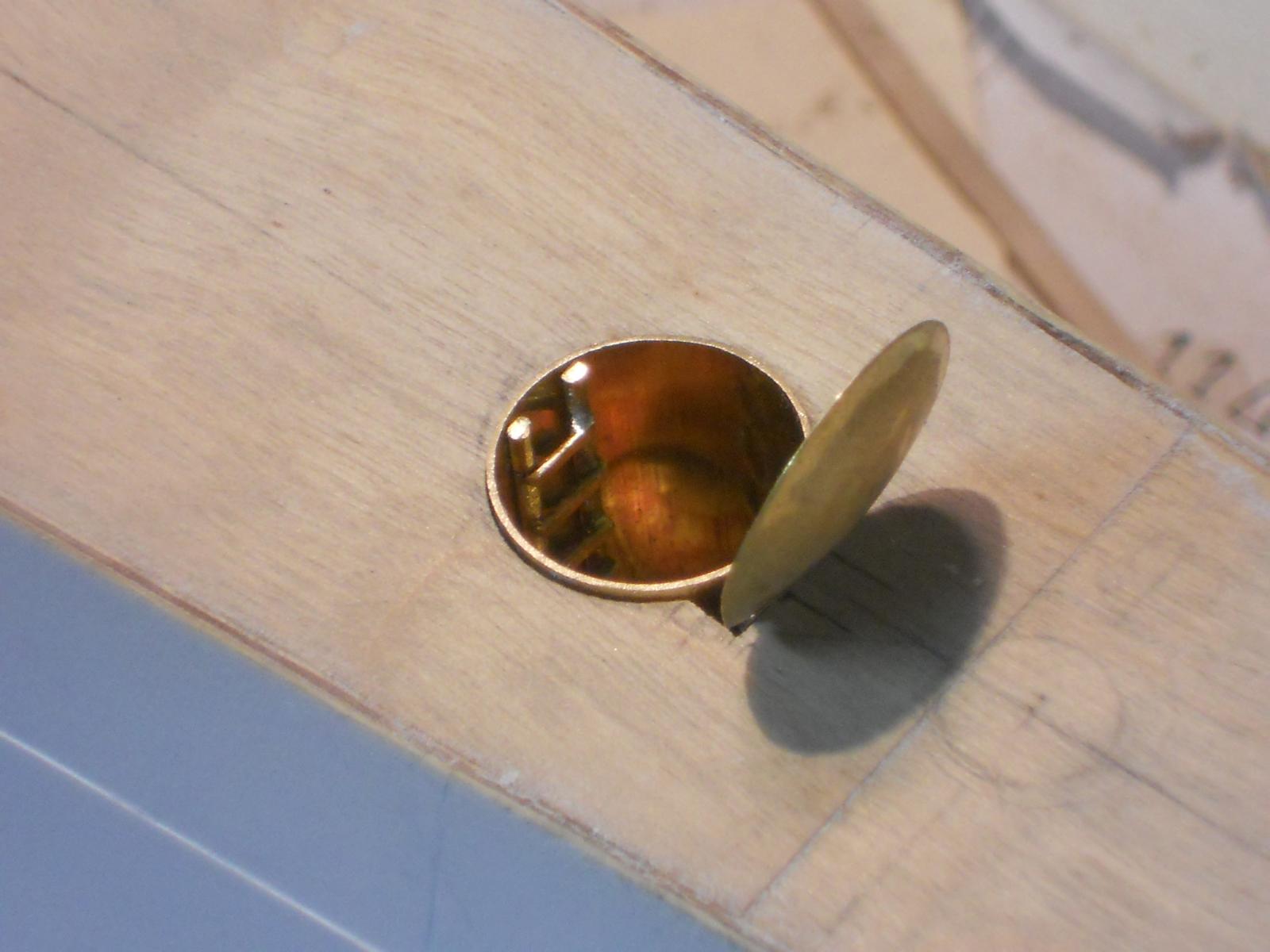
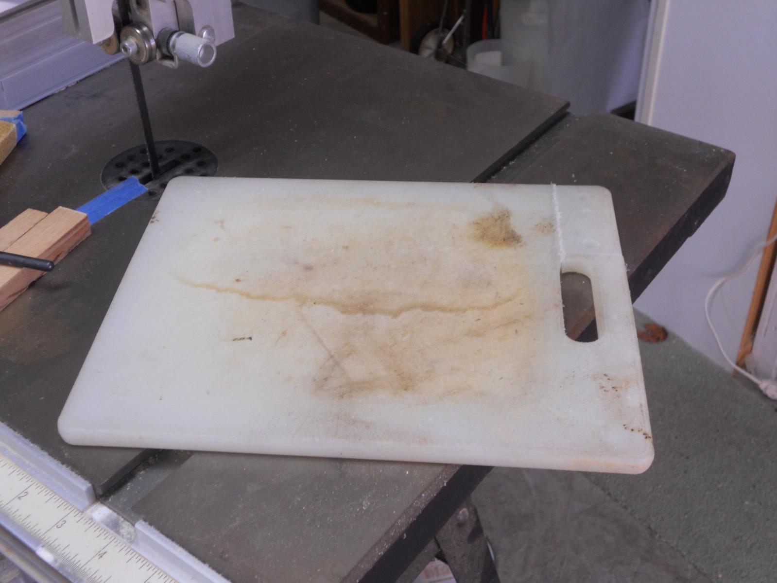
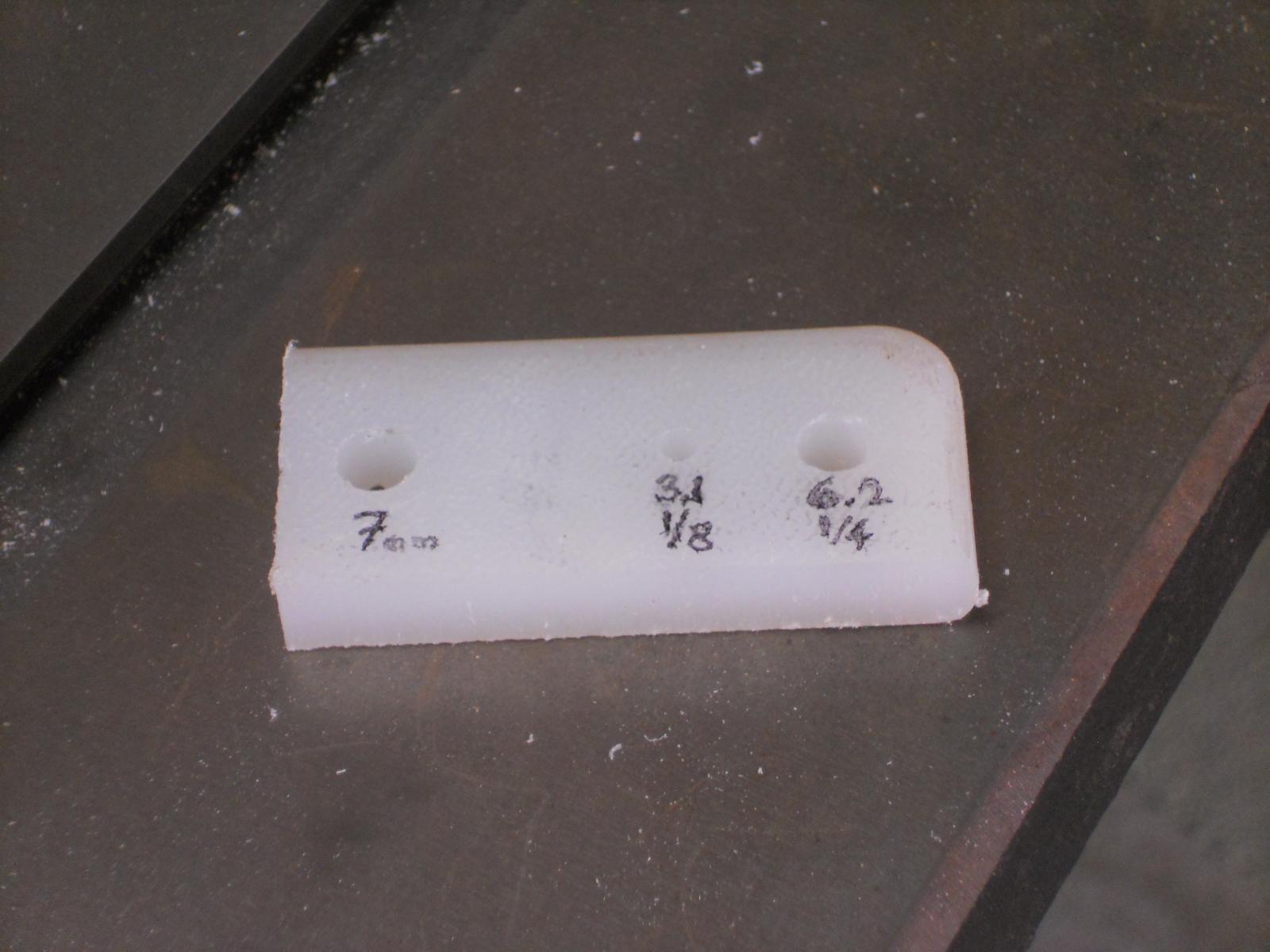
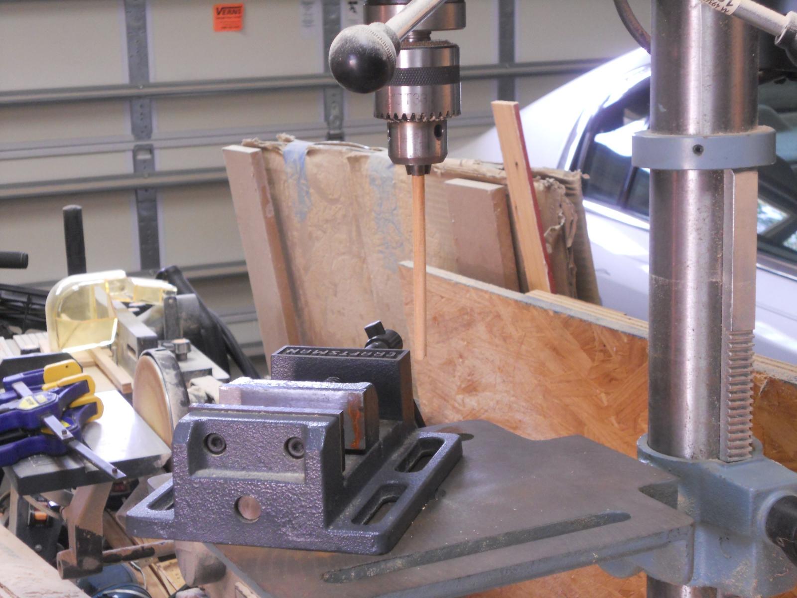
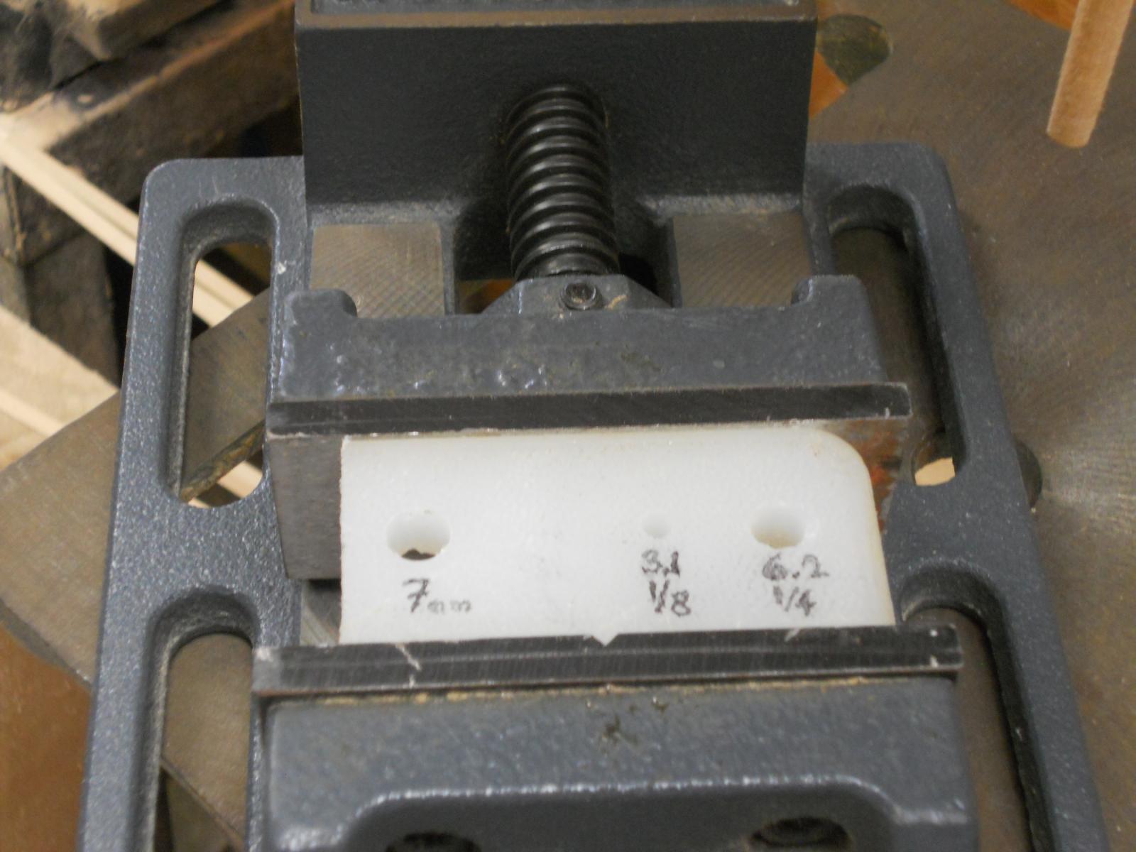
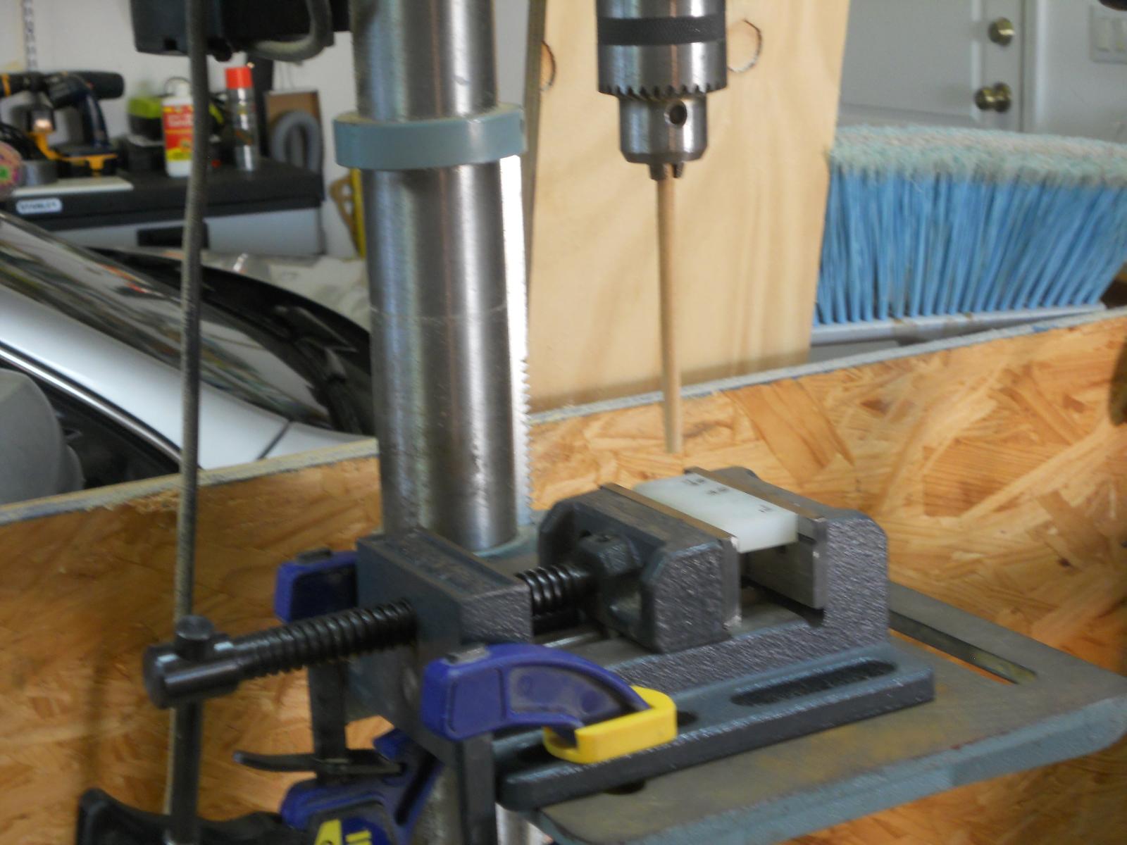
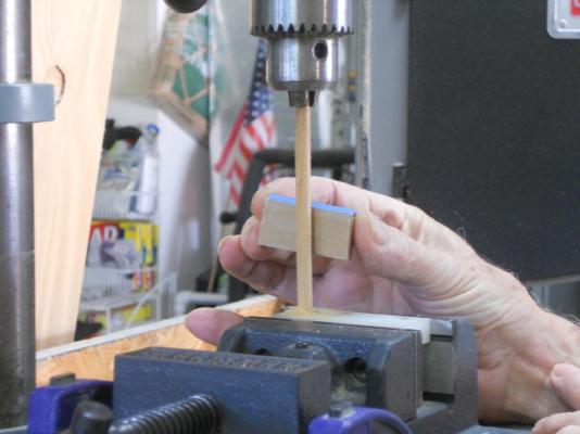
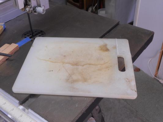
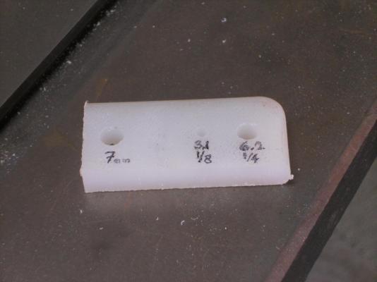
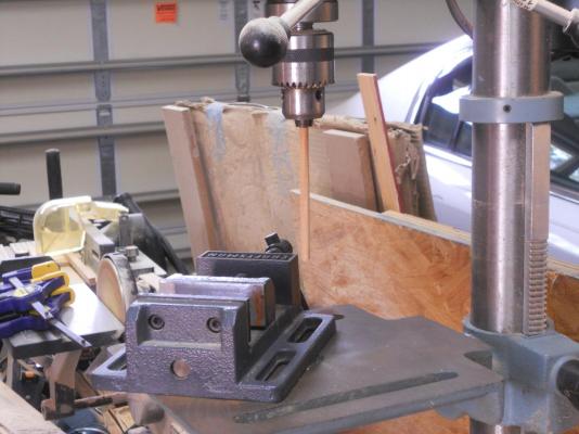
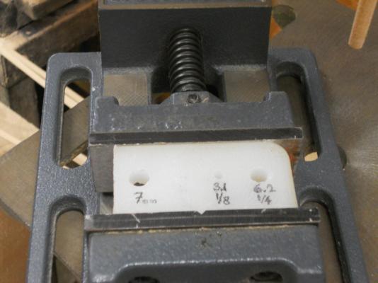
Hello Adriaan and Robbyn and J. Pett and whomever It's now Friday afternoon in sunny or kinda partly sunny, Palm Coast, Florida. Lunch is done with, mail has been looked at and It's time to share a few pics of my el cheapo spar sanding jig. First thing this morning I was hunting for my old jig but that proved fruitless so I made a new one just for yuns I also drafted the Admiral, my dear bride Gwen of now close to 51 years of putting up with me to take a few action shots. Naturally she asked many questions and I was obliged to answer them. Hey, her dad retired as captain with the KPM Okay here goes and remember that this can be adapted for use on large drilling machines down to the Dremmel. An old nylon kitchen cutting board. Pic taken after I already cut a small part out, an afterthought. This is the small part I cut out from the cutting board and already drilled a few holes in it. Make the holes a little oversize from the dowel(s) you are using for the masts and or spars. Here a test dowel is chucked in the Jacobs chuck. Be gentle with tightening your dowel. I used my nice and sturdy drill press vice to give me something solid and for clamping it to the drill press table. Here I have clamped the small nylon piece in the vice making sure it's kinda, sorta square to the dowel. It really doesn't matter too much because of the slightly oversize hole. Here I have positioned the vice with the nylon thingy under the dowel ready to raise the table up and engage the dowel into the nylon thingy. Here I have raised the drill press table up and the dowel fits nice and loosely in the hole. These are two examples of my sanding blocks. As you can see they are home made. The large one has a course grit sandpaper on it and the small one has 360 grit sandpaper for finishing. I find that using a long sanding block gives you better control and handle. The large one is very good for fairing ribs or bulkheads. To be continued on next post. Cheers,


- 1,038 replies
-
- 5
-
-
- King of the Mississippi
- Artesania Latina
- (and 1 more)
-
Thanks every one for visiting and your likes! @ Wayne, thanks for the URL on the German submarine history, very interesting indeed. I have made a decision on the net / cable cutters on my model. It seems that at this point in time no definitive info is available on when the O 19 received them. We do know that the build drawings show them and that earlier models had them. Also, I have a photo of the O 19 that is labeled 1941 where she does sport the cutters. I am going by the premise that the O 19 received the cutters sometime between 1940 or 1941 at the Navy base in Surabaya when hostilities with Japan could be expected soon. I remember my father saying "we are going on the Jap hunt" when he had to go out on patrol. I think that my guess is as good as anyone else's guess. So, they are going to stay. @ Freek, thanks for your input, appreciate it. Well, yes, it's possible that they stored the cutters below deck for future use, there is space for them as well as in the con under the AA deck. Again, at this point all we can do is guess. I like to think that they installed them just before the declaration of war. Before my father was transferred to the cruise "Java" he did sail with the O 19 as part of escort duty to and from Singapore and Colombo. Regarding the colors - - - if the person at NIMH thinks that below the waterline is grey that to me is not definitive. He is also guessing. My friend and mentor, Gino den Ridder has contacts in the Netherlands with inside info and he said that the O 19 and O 20 were painted in a red color below the waterline, green above the waterline to the deck sheer, and above the deck sheer it was light grey. I have given the reasons in a previous post and will stick with that. There is a model of the O 21 in the Navy museum in den Helder where below the waterline it is painted black, above the waterline it's green and above the deck sheer it's light grey. This boat was also launched before the war in Europe broke out and survived the war in the East Indies. After the war broke out and all surviving subs escaped to Australia they were painted in darkish grey. Thus - - - when most are guessing at the colors I'll stick with what Gino told me he got from his contacts in Holland as well as the model from the manufacturer. Back to the build, today was not productive as far as accomplishing things. I managed to make the domed lid for the most forward escape hatch and was planning on making the hinges but got side tracked. I also started to make the ladder for inside the escape hatch but then the lunch bell rang After lunch I decided to do some more drawing on the conning tower. That also needs to be done. My plan is to first show a profile with the location of the escape tubes and gun placements and other stuff. Then the top view with the same items. After that I'll do the sketching how I want the framing to be and where. There are a couple side doors on the starboard side and I like to make them operable. So, there has to be enough space inside to make it more or less real. I don't know if I can achieve that but we'll try Wish all of you the best and happy modeling,
-
Hello Robbin and Adriaan and others if interested, Yes, of course I'll recreate my set-up for yuns Give me some time like a day or two, I have something else going that takes priority. I'll just use my small drill press but the principle should work for even a Dremmel set-up. Cheers,
- 1,038 replies
-
- 3
-
-
- King of the Mississippi
- Artesania Latina
- (and 1 more)
-
Hello mark, yes, the net / cable cutters were already employed way before WW II on subs, including the Dutch subs. I have pics of the K XVIII and some other K boats before WW II with these things. For some reason they were not put on the O 19 and her sister boat the O 20 during manufacture. The drawings clearly indicate it. This could be a case of hurry up and let's finish these things but that doesn't fly either because the O 21 , O 22, O23 and O 24 had them and they were completed before the Nazis invaded Holland and sailed to England for completion. My father ran into many problems with shoddy workmanship and ran into a confrontation with their management and the Navy Board. He may have decided to accept the boat and complete it in the Dutch East Indies, which is a real possibility. I have a picture of the O 19 possibly taken in 1941 and it shows the "teeth." We would never know for sure because I can't ask him. I think that the Germans employed these during WW I but am not sure. Will have to look into it. Cheers,
-
Hello Augie, thanks for dropping in. Yup, but and there is a big but in my mind. I still have no report from any sub operation where this was actually successfully executed, i.e. cutting through a steel net barrier under water. As far as cutting mine cables, well just try to gut a line or cable that is kinda loose at one end. It tends to be dragged down with the boat and then - - - boom. It's much like pushing a wet noodle. I read one report of a US sub that sneaked into a Jap harbor through a minefield and back again. They hugged the bottom and moved ever so slowly and when they heard the cable scraping against the side they would steer away from it. They made it. Cheers.,
-
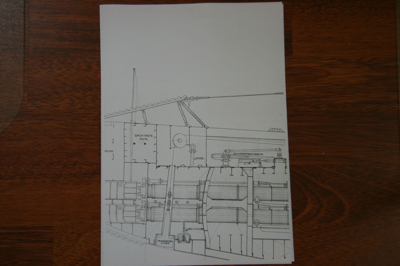
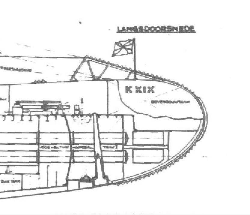
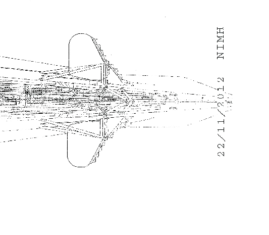
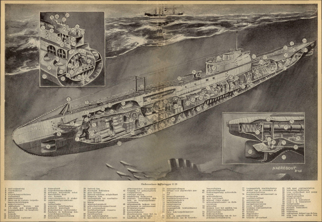
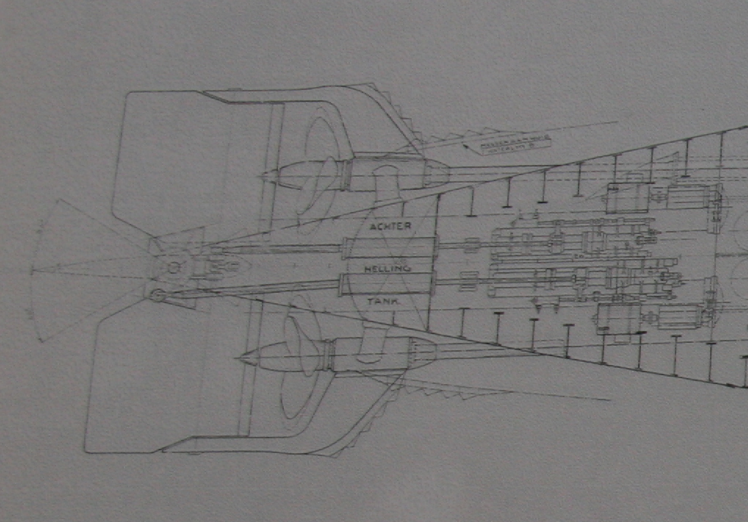
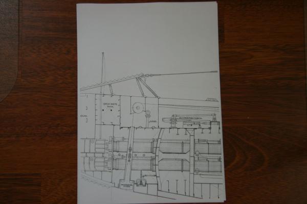
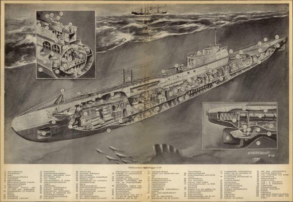
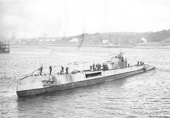
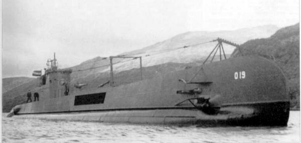
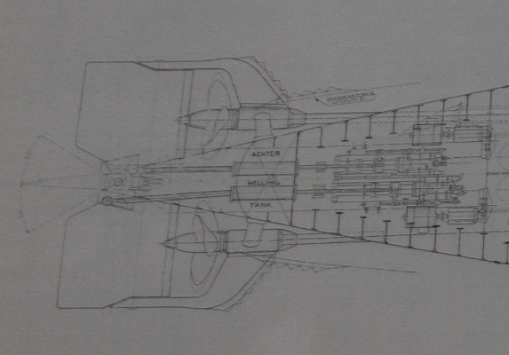
My sincere and grateful thanks to everyone who visited my build log and your "like" votes. @ Anthony, Boris and Brian answered your question. It was primarily aimed at cutting through anti shipping nets and cables. I am not so sure about mine anchoring cables though because of their vertical position and tend to be pulled down and forward with the boat. That's just my engineering mind thinking But who am I to make a definitive statement, I'm an airplane guy The question Boris has for me is where I found the data to show that the O 19 had indeed net / cable cutters brought me to my picture archive. I remembered that I saw them in several places but could not place where I'll blame it on old age - - - I guess though that with my one-track mind and now being busy with other items, such as the numbers and letter and the conning tower it slipped my mind. In any case, I could kick myself because right there near my work bench is a large copy of the deck layout and the profile drawings. On these are the net / cable cutters indicated. There drawings are copies from the original drawings out of the Dutch Navy Archive. That was the first clue and then I have photos of the O 19 when she was overhauled and converted to English ammo size and replacement parts sometime in 1943. Reason for the change was that the Japs sunk the Dutch supply ship that serviced the submarine fleet. Long story there. This overhaul was done Falmouth, Scotland. It is possible that they installed the "teeth" then because I have several photos with the O 19 in Scotland where she has the "teeth". Then I have a photo with the O 19 surfacing after a test dive in Scotland waters and there she shows the "teeth." The crux of the matter is that yes, she did have the net / cable cutters at some time after 1943. Even though the original drawings show her to have "teeth" installed but that was not done when she was being build in Schiedam, the Netherlands. She also did not have "teeth" when My father served on her from 1938 to the end of 1940. Remember that my father was promoted to Oppershipper (Adjudant) on January 1, 1941 and had to be transferred to the cruise Hr. Ms. Java at that same day. Sooooh - - - he may not have served on the O 19 with the net / cable cutter "teeth." Now, I can either remove them all and show her as she was when my father served on her or leave them on. Removing them may cause some damage to certain areas that I like to avoid. It may show but with some careful touching up and new paint - - - ? I really have to think very hard on this. I spend quite some time this morning just looking at the model and meditating, it's no an easy decision to make. There are also other changes made to the boat during her overhaul in Scotland that changed the silhouette of the boat. They removed the deck launch torpedo launcher and the doors, then they removed the forward AA gun placement and made the lower part and the cockpit in one line. They also changed the exhaust pipe arrangement. I am not making these changes though, she'll be pretty much like my father knew her, except then for possibly the "teeth." Let me attach a few pics to show the O 19 with "teeth." This is a copy of the original drawing out of the Dutch Navy Archive in de Hague. This is what Remco went for in our quest for the anchors. It only shows the mushroom anchor. Please look at the "teeth" on the antenna bracing. This is another copy Remco got for me. This shows the staboard side where the side anchor should be but is not shown. Also note the old I D number, still with the K for Kolonien (Colonies) and the traditional Roman numerals. This method was changed to designating all future subs with an O. The change took place in 1938 where The O was for domestic waters and the K for the colonies. Again, please note the "teeth" all the way around to the keel. This is also a copy of a drawing from the Dutch Navy Archive where it shows "teeth" on the propeller bearing housing / dive plane supports as well as the vertical keel / rudder brace. This is cut-away drawing with annotations. It also shows the "teeth." This shows the O 19 in Scottish waters, sometime in 1943. She has "teeth" Another photo of the O 19 in Scotland after her overhaul and modification, she has "teeth." I think this should suffice for now with data that the O 19 indeed had the net / cable cutters installed, but only some time after 1941. This may have been a British requirement because of the reasons explained above and to be to serve the Dutch boats in Australia. Cheers,


-
Hello Adriaan, If you have not yet "invented' a fixture to shape your dowels perhaps I have a very simple and cheap way to do that. The whole purpose is to prevent the dowel from whipping about and to give it support at the loose end. When I had to make the masts for my VOC ship I used a plastic or nylon cutting board and drilled a hole in it slightly larger then the dowel. This I clamped into a bench vice and chucked the dowel into my drill press. I positioned the vice with the cutting board under the dowel and raised the drill press table up until the dowel was in the hole. Next I clamped the vice to the drill press table and had at it. I could have held on to the vice with one hand and use the other with a sanding block but I like to use both hands. You can make a similar jig with your hand drill on a table or work bench. Just align your cutting board support in a vice, or your even your hand, so that the dowel will fit nice and loosely in the hole. Turn the drill motor on low to see how it behaves and when you have enough confidence in it working increase the drill speed and have at it. If the cutting board is narrow enough to hold it comfortably by hand you have enough control to make it work for yo. The whole object is to support the loose end of the dowel and this will work. Cheers,
- 1,038 replies
-
- 2
-
-
- King of the Mississippi
- Artesania Latina
- (and 1 more)
-
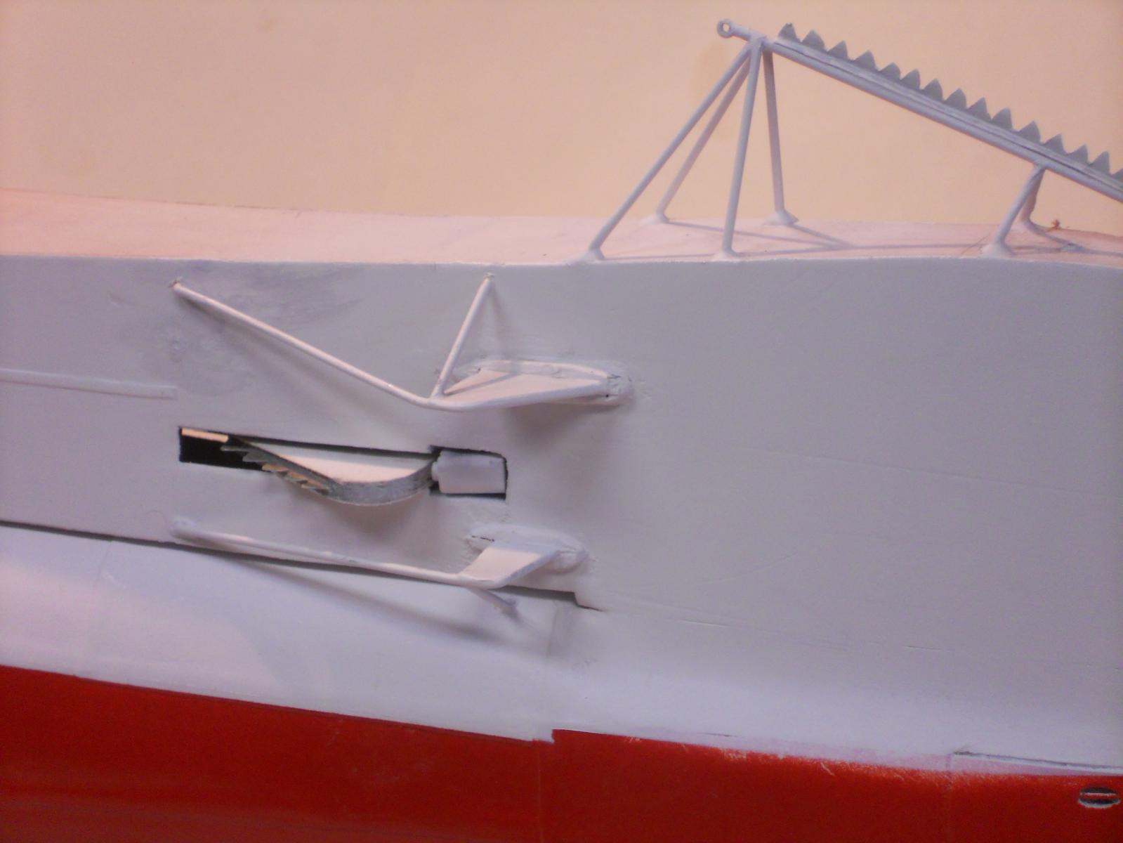
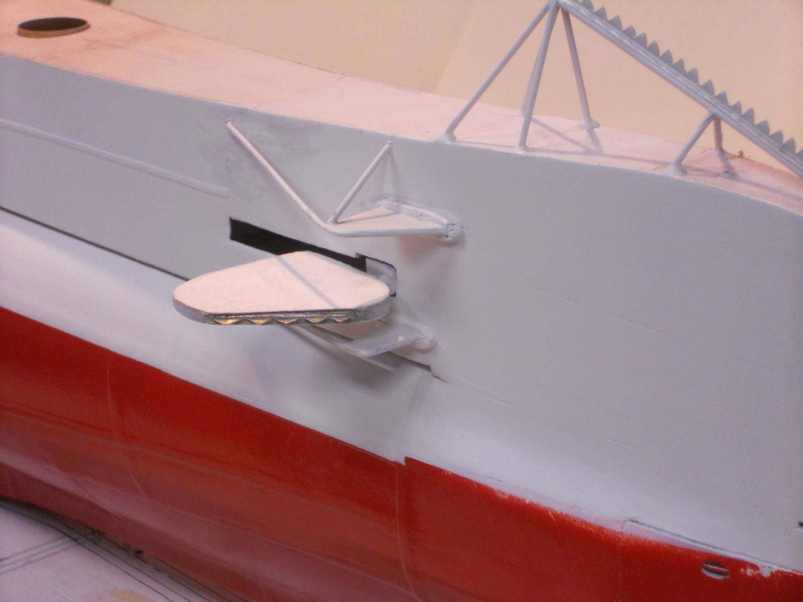
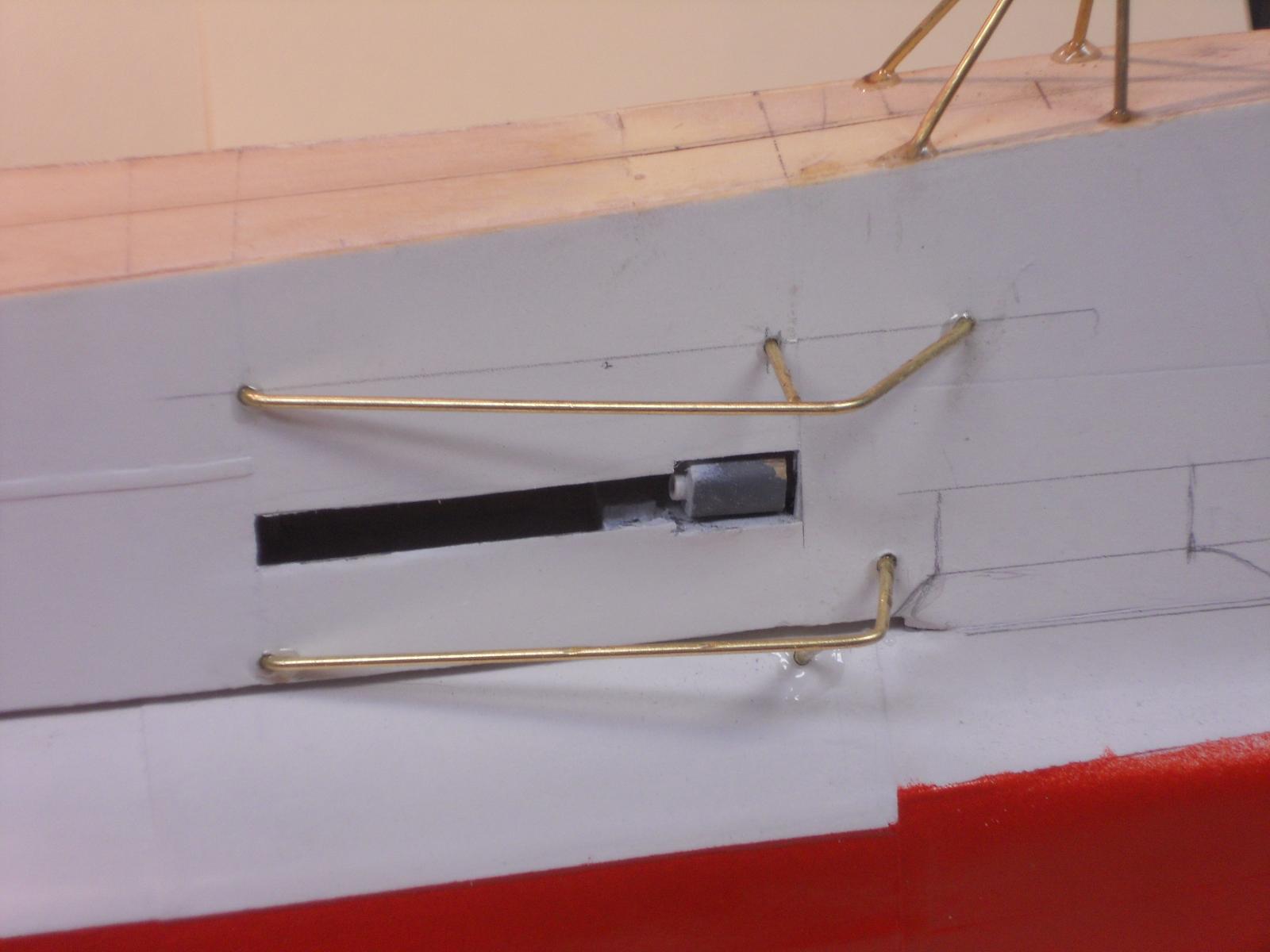
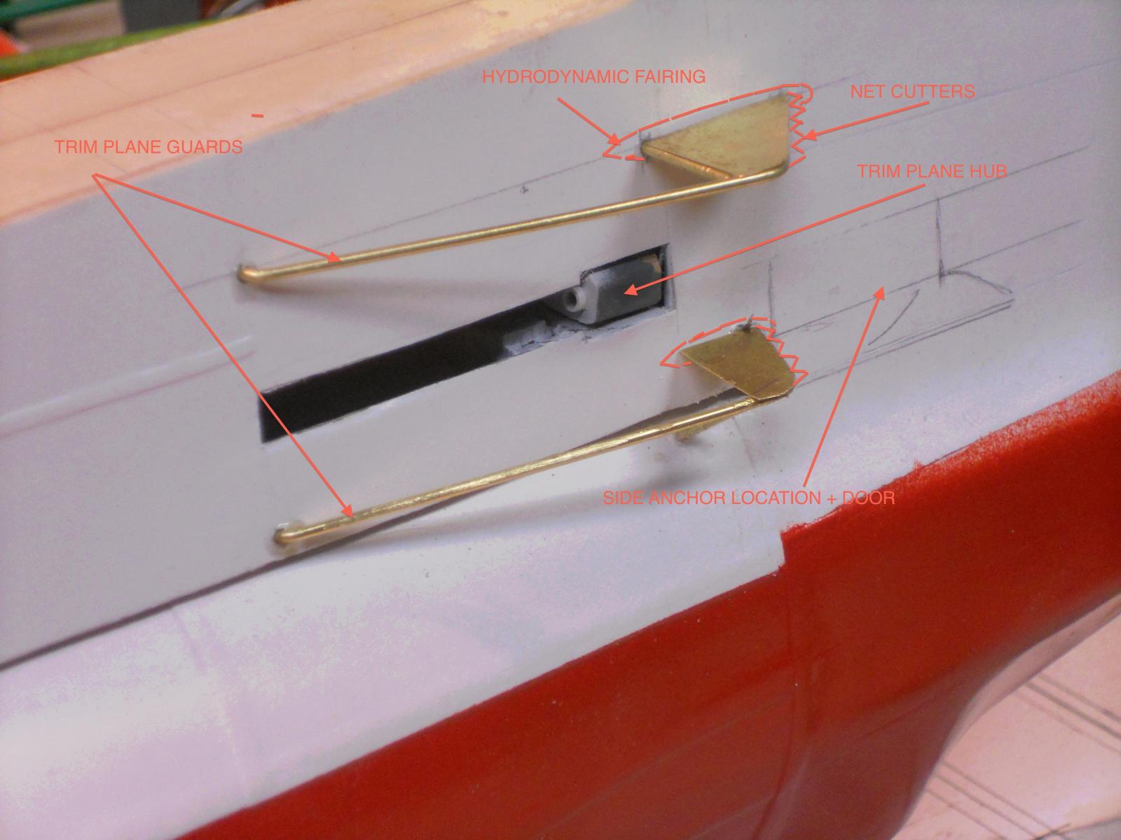
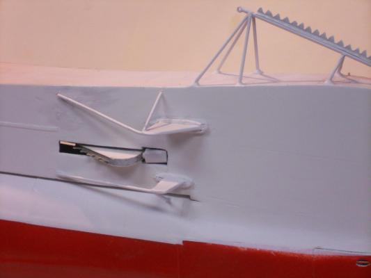
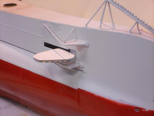
Thanks to everyone who visited my build log and clicked the like button, it's much appreciated. @ Boris, to answer your question I'll have to browse through all my photos in the O 19 file, very time consuming and will try to find the pic. I think I have seen it somewhere. I also believe that they were put on at a later date but not sure now. I know the O 21 had the net / cable cutters and she was launched just a few months after the O 19 and O 20. Thanks for answering the anchor question. FYI, the O 19 and O 20 had a "mushroom" anchor dropping down from the keel at frame 138 and they also had a side anchor on the starboard side. The model drawings for the O 21 does not seem to have a mushroom anchor but a side anchor is also not shown. It would stand to reason that all subs should have an anchor, but where is the question for those other then the O 19 and O 20. At least I know that for sure because of the original drawings from the Navy Archive. I completed the installation of the trim vane guards and the little fairings. These gave me more work then I anticipated but I think it dressed up the area. I'll hold off with adding the "teeth" to the leading edges till I find the pics I think I have. I may have jumped the gun with these. If the O 19 did not have them before January 1941 then I'll have to remove them because I want to depict this model as my father knew her and sailed on her. Please stand by for the final word on the "teeth." Here are two photos of the trim guards and the fairings. I temporarily put the trim plane into it's socket for effect. Another view but now with the trim plane extended. Cheers,
-
Thanks to everyone who visited and clicked the "like" button, much appreciated for yuns to stop buy. @ John (texxn5), yes my friend, there'll be lots of detail work coming. Some big, some small. The small ones seem to take the most time, like today. @ John (Lad), well, as I mentioned to John (above) the small stuff seems to take the most time. Wait till we get to the conning tower! @ Mark, yes indeed, all this small stuff makes the boat appear as she was in 1939 and 1940. @ Paul, thanks for dropping in and your comments. Pics will be made as I progress. I'm awaiting the continuation of your Scharnhorst @ Jan, thank you for your encouraging comments, and yes, the photos are for my benefit as well. It's a record for later use. @ Popeye, thank you my friend! @ Adriaan, as you well know with all the detail work on your King of the Mississippi. Talking about not much to show for a day's work, today is the day. I spend all day making four streamline fairings for the trim plane guards. They are cemented on but still need more trimming and fiddling with to make them look acceptable to me. Sorry, no pics - - - yet. I also did some more trimming on the antenna brace "teeth." They are close to the way I want them to look. Today I received the envelope with copies of several drawings Remco send from the Navy Archives. Wow, great stuff. The details on these copies are just what I need. I also saw that I made two errors. One is the loading beam for the dingy. The I beam I made is in reverse from what the drawing shows. I can either leave it be as is or remove a few items I soldered to it and reverse it. Then modify the attachments. It's a little more work but may work. The other item is the mine / torpedo loading dolly tracks. The drawings show them to be U channels on their side while mine are reversed I beams made from N gauge rail tracks. Not having the drawings when I decided to use N gauge tracks seemed logical, thinking that the dolly had flanged wheels like rail cars. To use U channel at my scale of 1:50 would be impossible to find or make. Soooooooohh, I'll leave them as is. Remco also made copies of the conning tower details with the AA guns and how they retract into their pressure tubes. It's pretty much as I thought it works. Wow, so much detail, just fantastic. Unfortunately, he could not find anything on the bow side anchor. This is really not much of a problem because I understand how they look like but having them stowed inside the bow section will be a no go. Reason is that that area is almost solid with ¼ inch framing. I don't think I'm going to carve a large space into it for the anchor. However, as I mentioned in a previous post, I can make the anchor and let it rest on the display board just as the K XVIII photo shows that Freek posted. I can attach a cable to it and let that go up into the hull. I will have to make a separate door to at least simulate the real thing. More tedious work. So, that's it for today. Y'all have a great evening or day and happy modeling. Cheers,
-
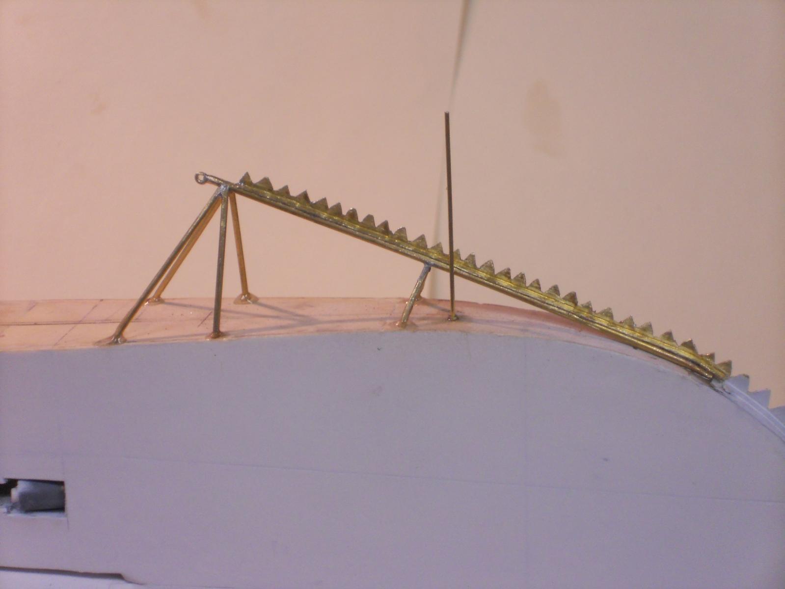
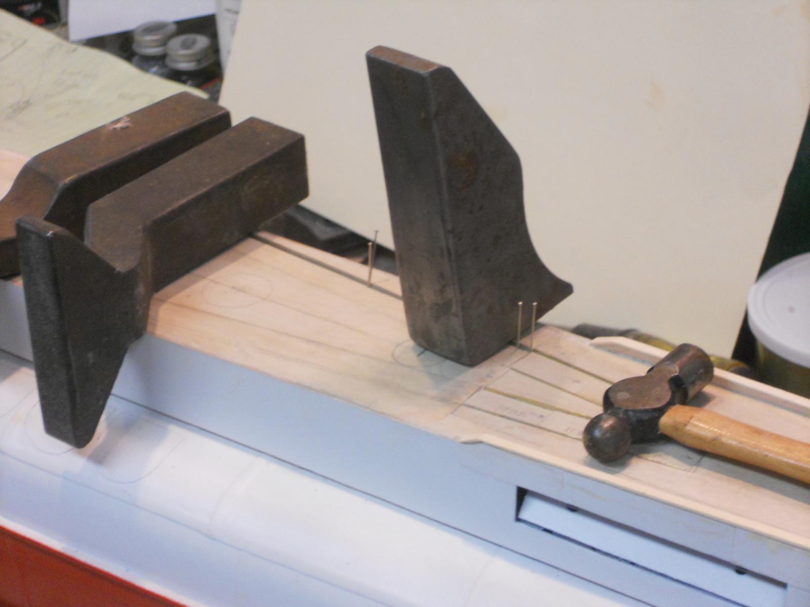
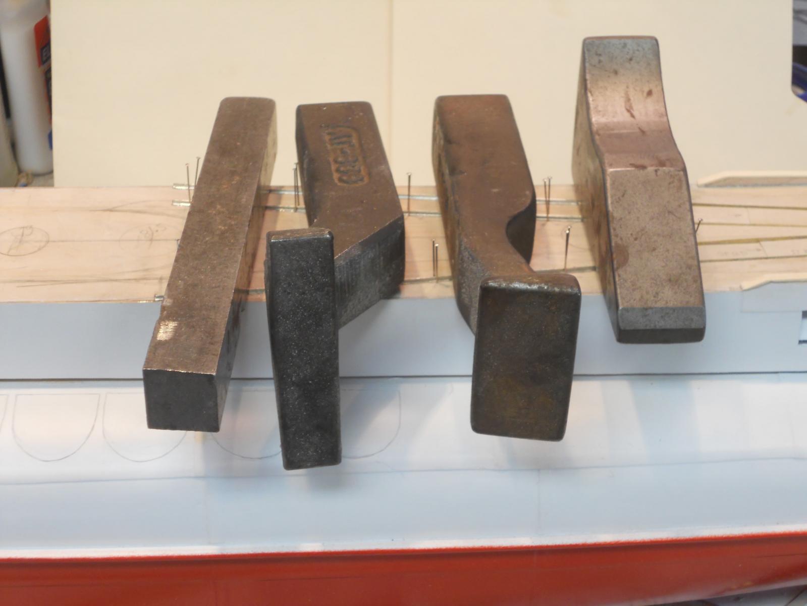
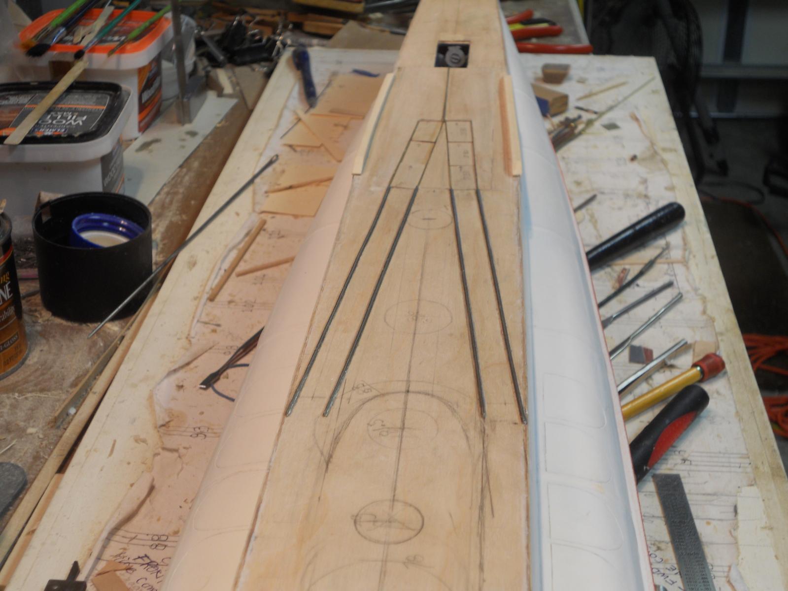
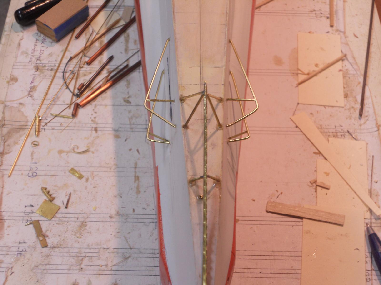
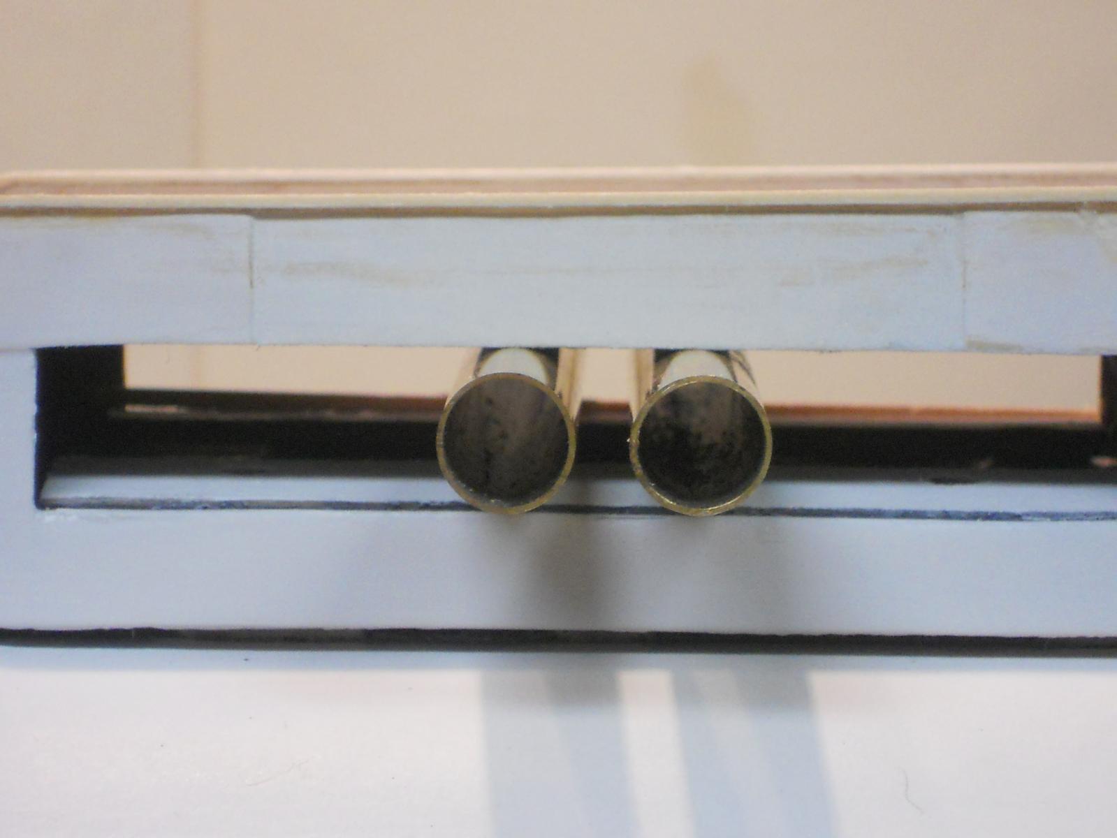
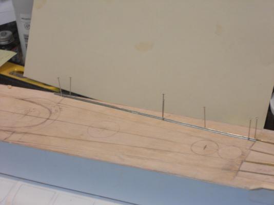
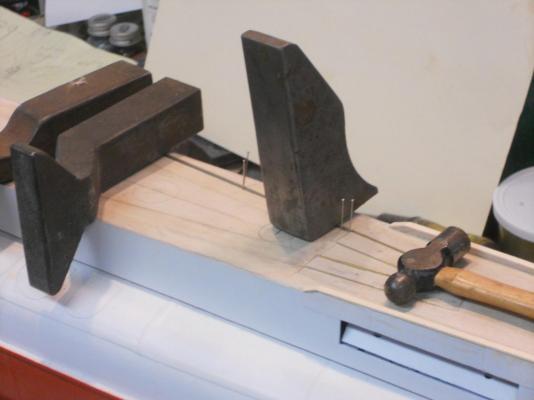
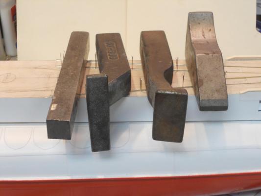
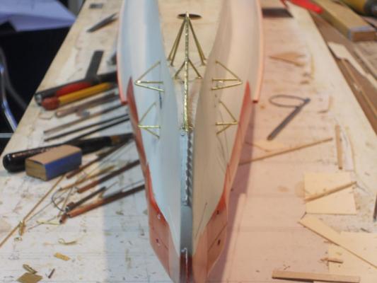
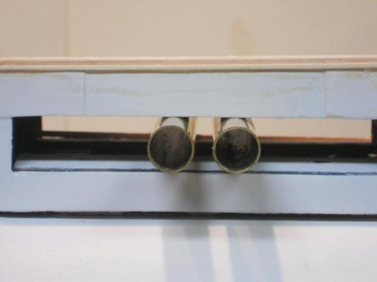
Today was rather productive tackling detail work. I made and installed the "teeth" a k a net / cable cutter on the bow antenna attaching brace. Then moved a little further aft and cemented the torpedo loading dolly tracks to the forward deck. As the cement ( 5 minute epoxy) was curing I started to make the dive plane guards. I made them from 1.5 mm brass rod, bend them in shape, drilled holes in the appropriate places in the hull and epoxy cemented them in. I used the O 21 model drawings and several photos for the location. The lower one needs to stay clear of the side anchor. As you can see I have marked the location. I think that they made the anchor closing door hydraulically operative. I may want to simulate it open with the anchor showing or lowered to the display board. Hmmmm, that would look rather nice Tomorrow everything will be soldered and net / cable cutter teeth made and soldered on to the guard leading edges.. Not much to show for a day's work but it's all very time consuming. Okay, here are a few pics for all yuns to look at. We don't want to disappoint Sjors now, do we? Here the net /cable cutter teeth have been soldered to the antenna brace. It's still raw and needs to be dressed yet. The small vertical rod is the bow flag post. It sticks into a small brass tube cemented into the deck. I have used sewing pins to secure the track in position ready to be cemented on with 5 minute epoxy. Here the track is being cemented an I am using a bunch of rivet bucking bars to hold to down to the deck. All my sheet metal tools still come in handy I found that I could cement two tracks at the same time after I "pinned" them in the right place. Mixing small batches of epoxy began to annoy me All four tracks are now cemented to the deck and neatly cleaned up. I'm happy. The trim plane guards are cemented in with 5 minute epoxy and waiting to cure. This shows all the detail work I did today from above the bow. This is a head-on bow shot with today's work. I made an annotated copy of what was done today. I still need to make more teeth and solder everything together. I also need to make hydrodynamic fairings around the forward parts against the hull. I'll make them from basswood and cement them on with epoxy. I couldn't resist putting a couple of the 10 mm brass (torpedo) tubes in the launching area to show their future home Cheers,


-
Thank all of you for visiting my build dock and your like votes, much appreciated !!!! @ Wacko Joe, yup, I have a big box full of plane kits but had no time to assemble them. Airplanes have been my life. The bug bit me when I was 7 years old and never left me. But I also like ships and boats though. I guess I have high octane gas, JP 4 jet fuel and salt water in my vanes Cheers,
-
Thank you very much Freek for the video! I watched it several times and I'm impressed with your persistence to make it work. I won't go that far with my build of the O 19 though, I may an eye in the process Cheers,
-
That's one sweet looking ship Remco! and a lovely chisel box too
-
Hello everyone and thanks again to Ian, Wayne, Boris, Pete, John (texxn5), Andy, Adriaan, Daniel, Remco, Anthony and Popeye for dropping in and your like votes. Not to forget all who commented, @ John (Lad), thank you and yes indeed, all those little details make her come alive. @ John (texxn5), oooooh yes, I love those flying boats! The best of two worlds, a boat that can fly! Well, actually there are flying boats and I did work on them about two lifetimes ago but never flew one. The ones this fellow makes are unique. @ Wacko Joe, something for your next build Joe @ Boris, thank you my friend, appreciate your compliment! @ Wayne, thank you also for your compliment and yes, details make or break a model. @ Adriaan, Hartelijk dank voor je compliment! Thank you for your compliment. @ Popeye, yes, I did read that book with our daughter when she had to read it for school, great stuff. Well, today was my day off from the shipyard. But the mind is always working on the next steps to be done in the right order. Now it's all small detail work that needs to be made and installed. Even at this scale most of the stuff is still very small and tedious work. All y'all have a great and productive weekend. Cheers,
-
She's really looking fantastic Adriaan! Cheers,
-
Hello John, yes, your assessment is correct, it's a little too large when comparing it to the pic of the real ship. I agree with using boxwood. It's a fine grained wood that you can cut down into very small pieces and can still work with, like drilling small holes in it. What kind of material (metal) is it for the protective grill rods in front of the windows? Did it come with the kit or do you have to supply that yourself? What did the kit manufacturer recommend? Like all of us, sometimes we have to redo something, so don't feel bad. You are doing a great job to make your ship look as close to the original and you'll lick this minor setback too. Cheers,
- 2,250 replies
-
- 1
-
-
- model shipways
- Charles W Morgan
- (and 1 more)
-
Hoi Freek, she will look exactly like the original as seen from the shape of the hull. btw, Queen Juliana is my most favorite person, said from personal experience. That one cent piece should serve your O 1 well. Love the pic of your K XVIII as well. Cheers,
-
Hello Nenad, happy to hear you are getting over that flu big. Super nice looking bulwarks, great job! Cheers,
- 4,152 replies
-
- 1
-
-
- cutty sark
- tehnodidakta
- (and 1 more)
-
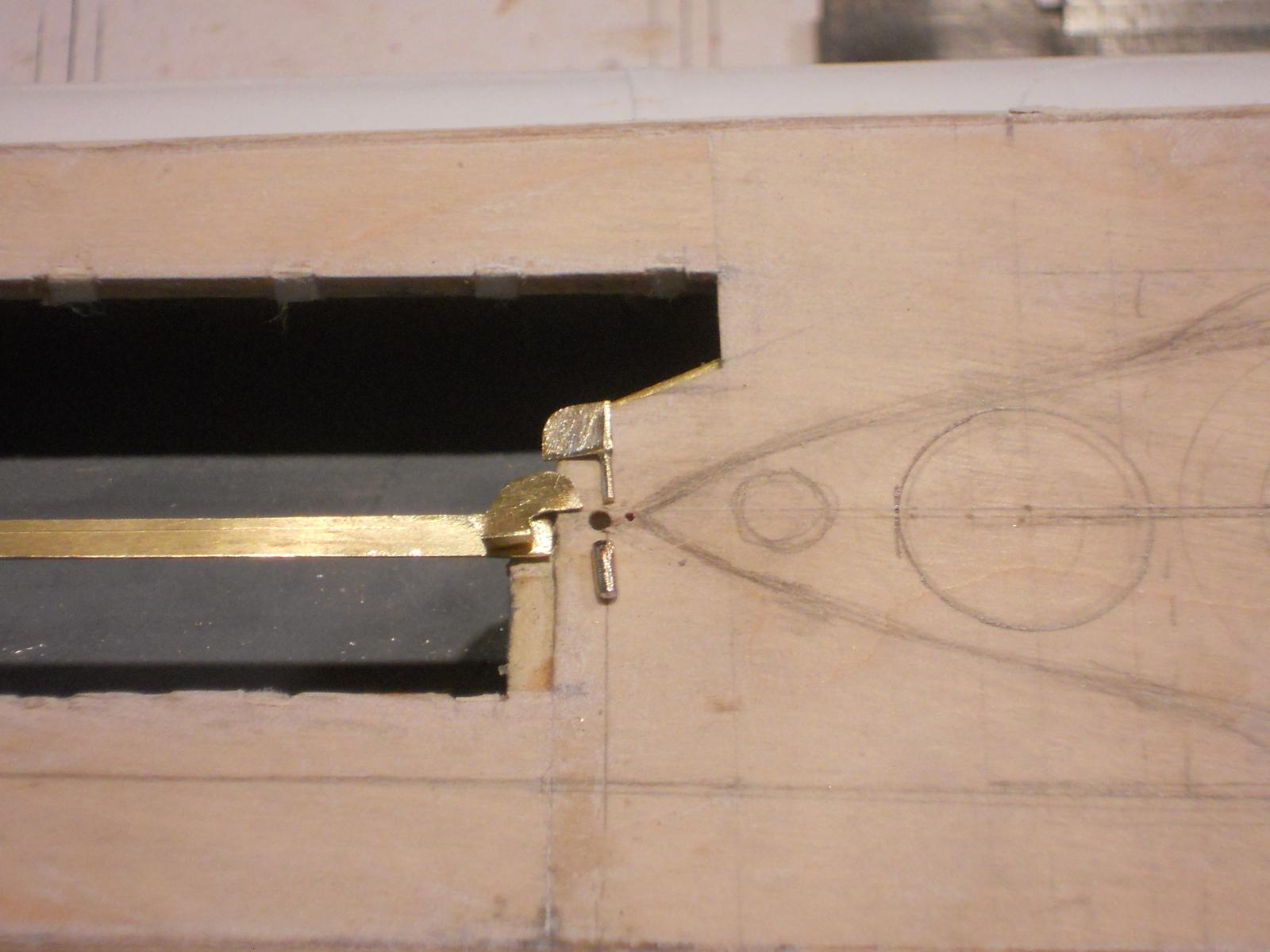
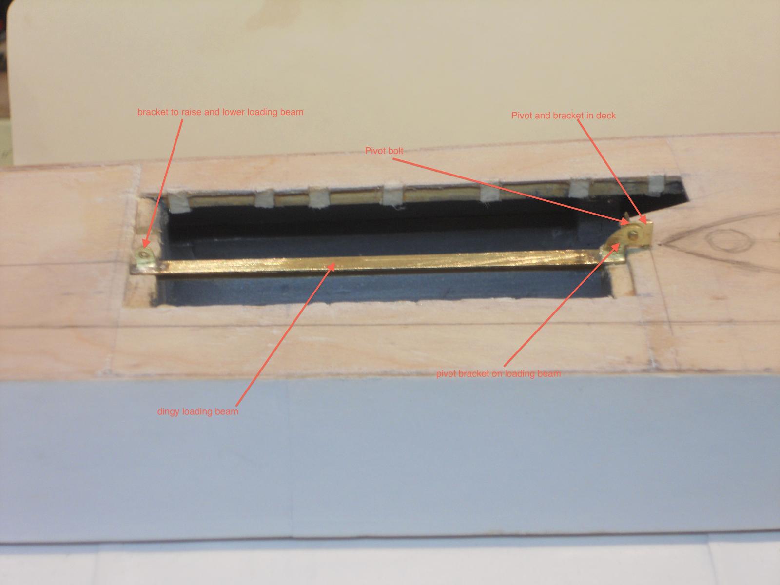
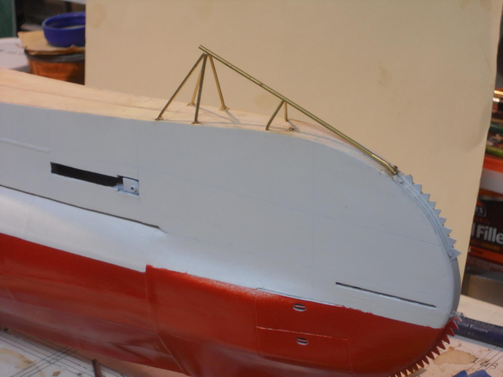
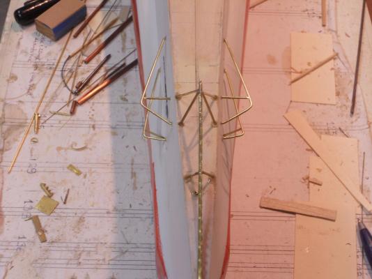
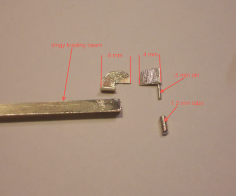
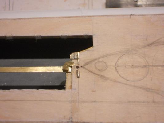
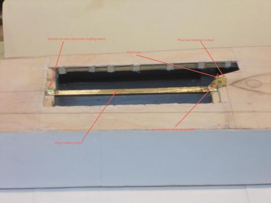
After I came back from my dentist visit for a follow-up check on the double implant in my left upper jaw I spend a few hours in the dockyard doing some small stuff. Everything looks very good in the jaw btw. Could possibly get the crowns early January next year Hip, hip, hip, hurray!!!!! Oaky, First I cut the stern crew escape hatch and loosely put it in its hole, then proceeded to the bow and made the triangular antenna brace slash net / cable cutter brace. All it needs now is to secure it at the front end and make the net / cable cutter and solder it on. I also finished the dingy loading beam. It can now be lifted up and swivel. The pics below will explain it. I had to remove the hatch doors though, I'm replacing the paper hinges with metal ones. Sounds like not much work but it was all very time consuming to make it look right. Here are the pics. These are the parts for the forward end of the dingy loading beam. I forgot to put an ExEcto knife blade in the pic for scale comparison so I annotated the pic instead. What you see here is still rough and needs to be dressed yet. The little tube goes into the deck right behind the con and that little "thingy" above it fits inside. That 5 mm piece is soldered to the end of the beam. A .8 mm holes will be drilled in these pieces for a .8 mm "bolt," which is a small brass nail. This shows the beam installed with the swivel parts laid out where they go. Here is the finished beam installed and ready for action. I drilled a .8 mm hole in the bottom leg of the T beam and soldered a small bracket to the aft top end of the beam for a clevis to hold a pulley on a hook. This tackle will go to the top-aft of the conning tower to raise and lower the beam and to let it swing. This shows the bow antenna / net / cable cutter brace. Here it is not yet soldered together, which is now done. It needs to be secured in the front by cementing a .8 mm brass nail into the wood of the bow. Then I have to make one more piece of teeth to solder to the top brace. This is made from 1.2 mm brass tubing and the legs are 1 mm brass rod. Here is another view of that structure. In several of my previous posts are actual photos of that structure you can look at for comparison. No need to add them here again. Cheers,


-
Wow, a great amount of visitors to my dockyard, thanks everyone for dropping in and for your "like" votes. Hey Sjors, I'm running low on pop corn, the machine needs replenishing @ John (Lad), thanks John for your very kind comment, yes, she is coming together! @ Wacko Joe, thanks and pics are coming! @ Mark, isn't it amazing what a little paint can do The only way I figured to simulate steel plating is with heavy paper. So far it's working for me just fine. Even when looking at it close up it looks like steel plates, except for the absence of rivets. But - - - we'll have to forego that I'm afraid. Too costly. @ Daniel, yes indeed, caution is in the order, even with this model, they are sharp! How do I know? Hmmmm, cut myself I don't know how effective they actually were in penetrating through barriers. The example you looked at for a paint scheme is of the model of the O 21, which was build a little later and of another class. They may have switched from red to black at that time. According to the model that the ship builder made and from what Gino den Ridder told me it's red from the keel to waterline 7, then a forest green to the deck line and everything above the deck was light grey. As I mentioned before, the red will appear dark brown in the water to blend in with the Indonesian coastal areas. The green would blend in with the tropical coast lines and the light grey with the sky. This was a minelaying sub to serve in the former Netherlands East Indies, so most of it's time was spend near the coastal areas. In any case I'm following the paint scheme as she was in 1939 when my father served on her till January 1941. The net / cable cutters are hand made and soldered to brass flat stock. very tedious work and prone to cutting my fingers and hands. The "blue rust bucket" is actually a plastic container my wife uses for garden debris. It comes in handy as a paint stand @ Popeye, yes, I'm very happy with the way she's turning out. Thanks for the "Peanuts" cartoon So, now we know that poor old Charley Brown has a kite eating tree and a kite eating sub! Bwaaaa, haaaa, haaaa Sorry it wouldn't allow me to click on like. @ Sjors, thanks for liking my paint job, appreciate it. And painting your fence? No sweat, just supply a bed, three meals a day and a few pints of beer - - - and you buy me the plane tickets @ John (texxn5), thank you john and yes, we can now devote time for "stuff" above the deck line. And yes, I did hoist a very cool Leffe to celebrate. Just watch out with that skylight on your ship, I can peek in @ Popeye, Tom Sawyer? Was he not that little dude who went fishing in the Mississippi River watching the Delta Queen go by? @ Ian, thank you. You feeling tired watching my progress? Now you know how I feel after a day in the garage, I am standing and walking around the build, no break, except for lunch and chores for the Admiral. And that at my highly advanced age - - - - - @ Augie, hey, nice to hear from you! Thanks for your comment. I think that my father would be pleased as well if he could see it taking shape, he loved that boot. @ Mobbsie, give my regards to Sjors and Anja and ask where my plane tickets are so I can paint their fence Cheers,