Piet
-
Posts
3,568 -
Joined
-
Last visited
Content Type
Profiles
Forums
Gallery
Events
Everything posted by Piet
-
 Hey John, nice looking shitters you got there - - - oh, I'm sorry for the foul language but Sjors started it and the Spanish not to forget re your pics, yeah, if all else fails check the how to instructions Say hi to Di and cheers,
- 2,250 replies
-
- 1
-

-
- model shipways
- Charles W Morgan
- (and 1 more)
-
Hey Popeye, that looks awesome! Agree about the semi gloss or mat finish. These old ships didn't shine, they were all rough working ships. Yea, take a break on this one, you did good and now a change of pace, rigging. See you there. Cheers,
-
Hey Popeye, you like it eh, me having trouble with computers Airplanes is my game but that's in the past, now its ships and art, yeaaaaah Are we having fun yet? Hope to hear from the computer fixit shop soon and get my big Mac back Cheers,
-
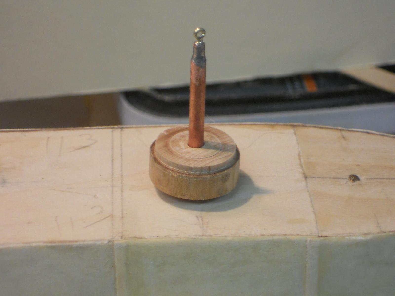
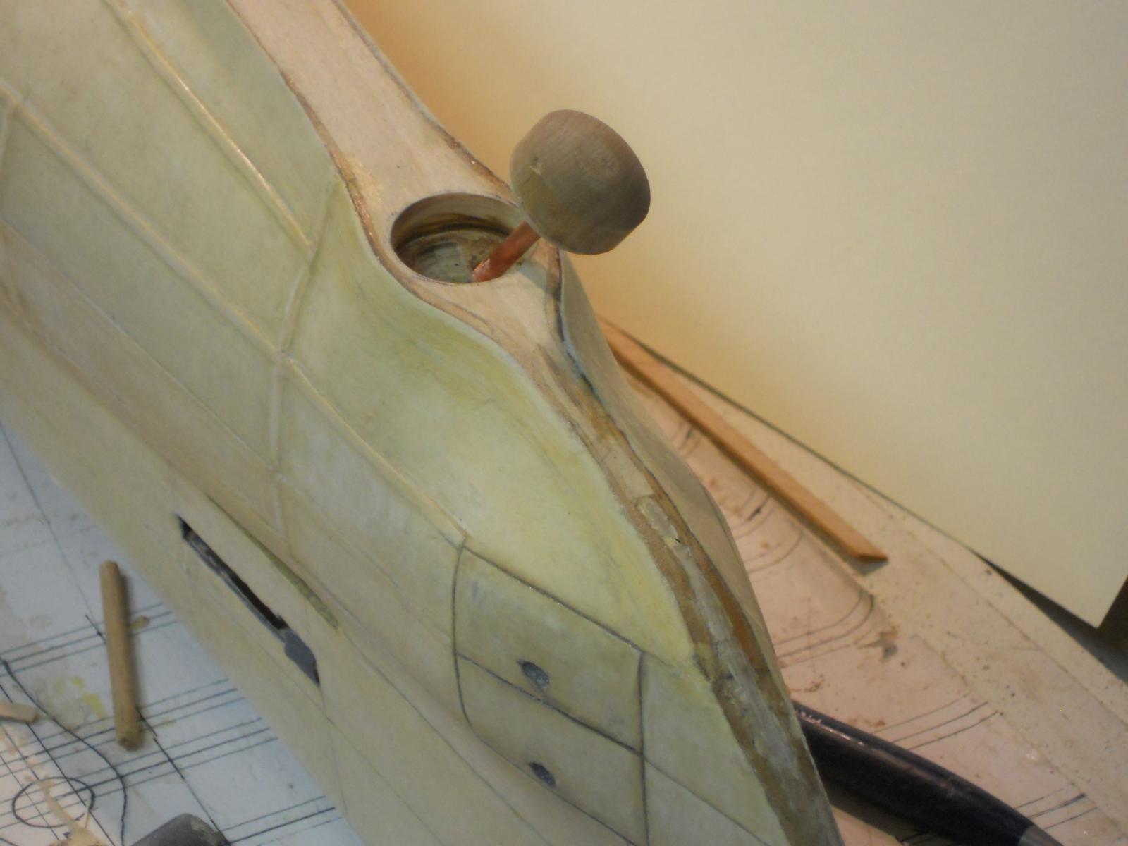
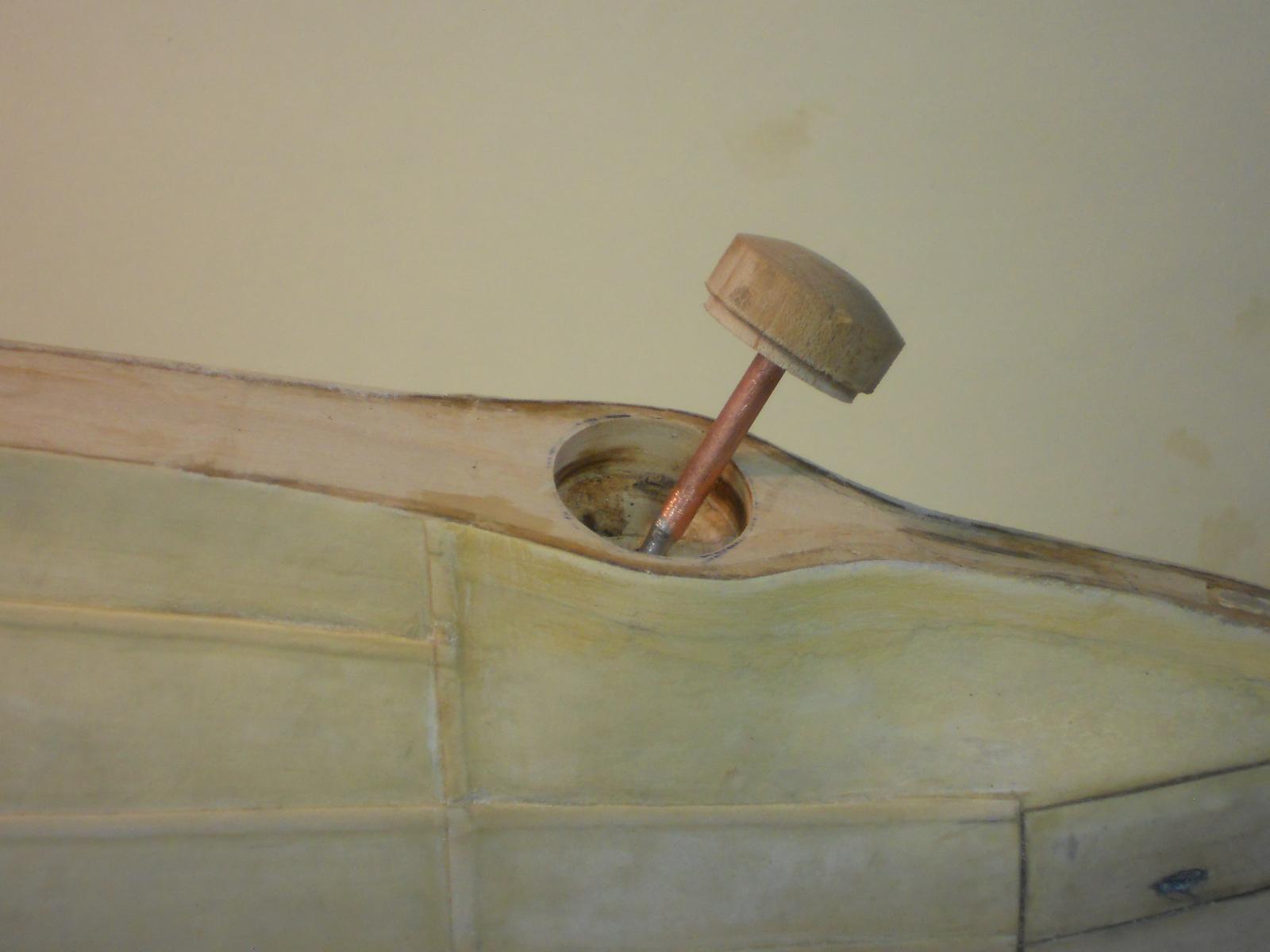
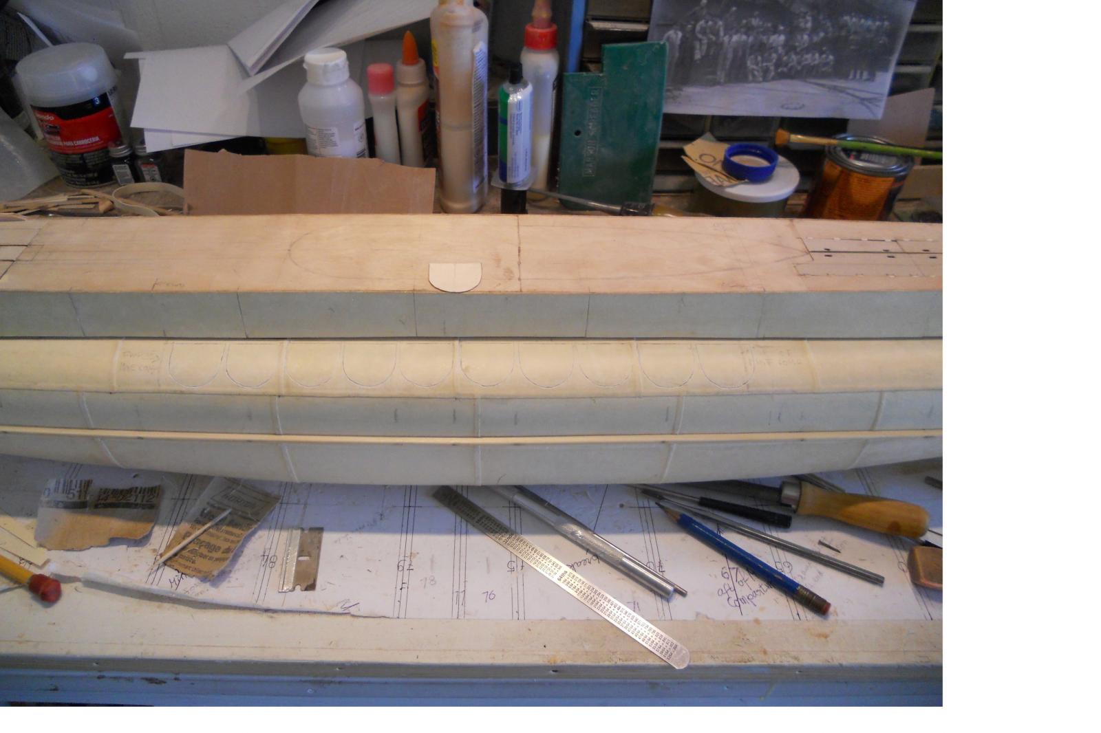
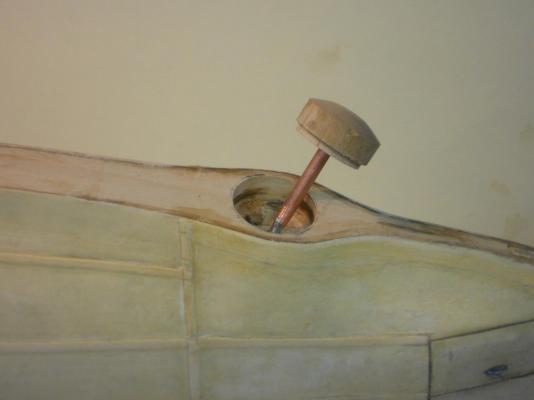
Hello all, I reduced the size to a lot less pixels and this confuser likes it, so here they are. Hope yuns can still see them without a magnifier. This is the mushroom anchor still unfinished. Here I placed the anchor in the receptacle. I plan to attach a "cable" to it so it can appear to be ready to haul back up when I leave it outside the boat when on display. This is another shot of the anchor to give you some perspective. Cheers,


-
Hello everyone and thank you John, Mark and Ian for dropping in. @ John, a storm, Sjors is getting a storm? What do you mean he is getting a storm, Sjors IS a storm Well, I hope for all the Dutchies that it'll cause no damage and harm. That must be the same storm they are having in England. We do know about them things, they are called hurricanes here. Okay, today I spend again quite some time picking at some "stuff" on the boat but I figured I should test a piece with paper with poly to see if my enamel primer will stick. It seems okay but I'm still nervous though painting over the poly but the enamel primer and poly should be compatible. In the meantime I made and installed the net/cable cutter to the vertical keel, turned out quite well. I also put one light coat of primer on the exposed wood parts of the dive planes, rudder and prop shaft supports. It needs one more coat. Then I started to make the mushroom anchor and prepped its little "house." I intend to make it so that I can either leave it in or drop it down. For a static display it may look okay. I may put a coat of primer on the hull so I can see better where any blemishes are that still need to be corrected. The sun should be shining and it'll be nice and warm so I can paint outside. Here are the pics of today's work. Well now, the pics will not upload I'm using the Admiral's MacBook pro laptop and reduced the size to the recommended amount and even much less for a trial but no dice. Right now I have no idea why it wont behave Computers, give me an airplane to work on and I'll fix anything on them things, but computers? Infernal machines they are. Cheers,
-
Thank you all gentlemen for looking in and your kind comments. Yes, Ian, she can bite now Today was spend sanding and again sanding. I also wiped her down with a damp rag with some solvent to remove most of the sanding dust. Tomorrow some more touching up and fiddling around trying to correct some of the ragged edges and then making more "teeth" for the vertical portion of the rear keel. When she looks satisfactory then I may paint the lower part of the hull in red. When that's dry it may just be the right time to start prepping for the conning tower The hull part above the waterline can be painted any time and it'll be green. Everything above the deck will be a light gray with a teak colored deck. Cheers to all,
-
Looking very nice John ! Glad you are building again Hmmmmm, better treat that fire hydrant with Preparation H to shrink it so Cosmo can do what doggies like to with hydrants Cheers,
-
Oooooooh - - - that looks very good Popeye and kudos to Andy for noticing Cheers,
-
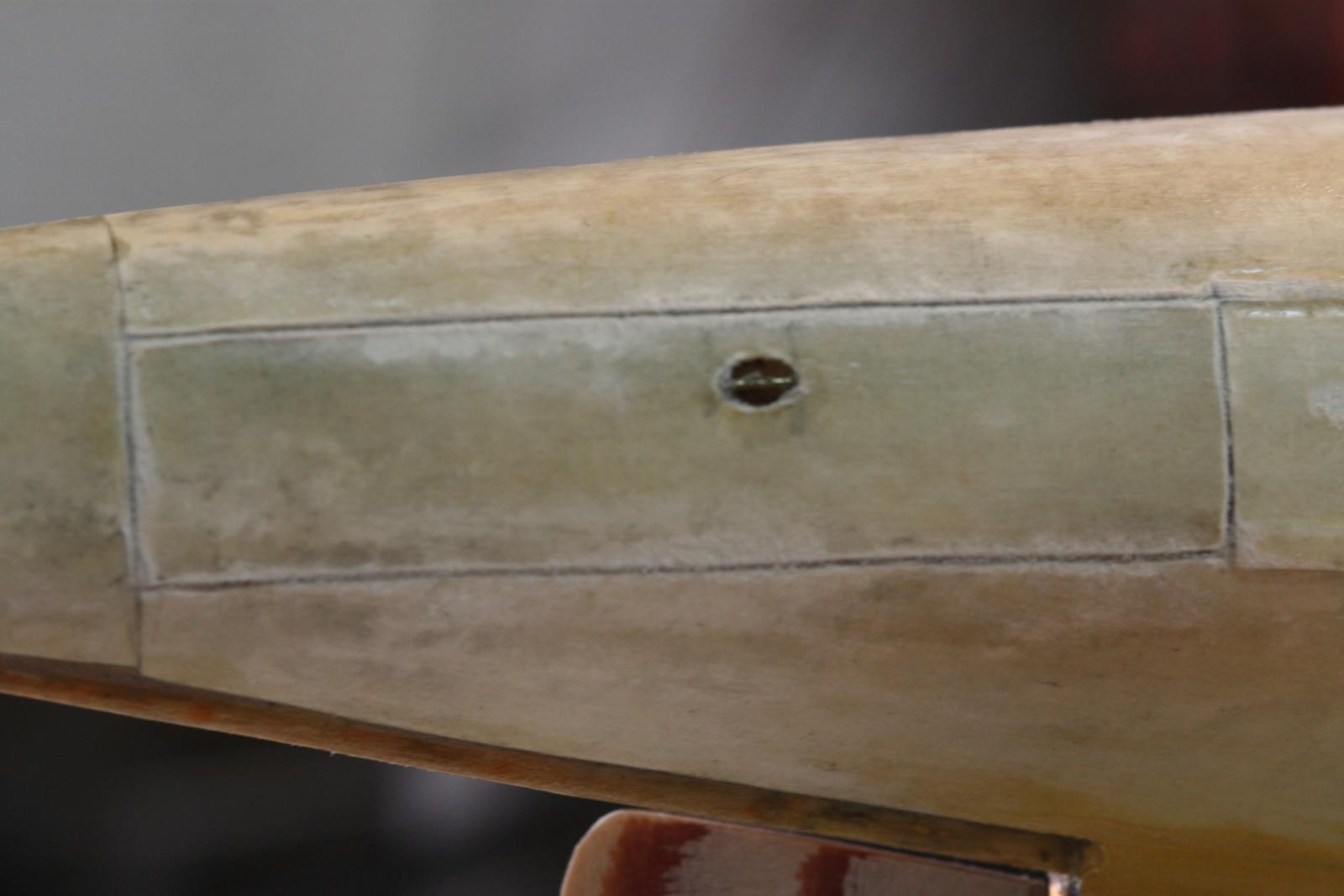
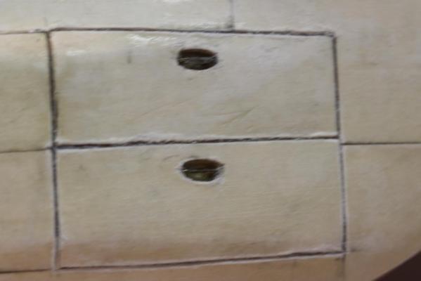
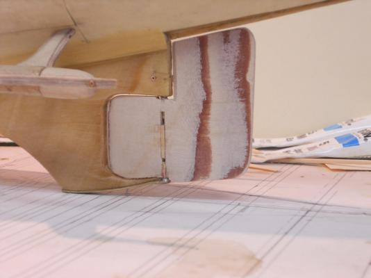
Hello everyone, No word yet on my poor computer but I finally found out how to reduce my photos on this laptop I made some close-ups with my Cannon with the 100 mm micro lens. Unfortunately the lighting in the shipyard was low so the depth of field was too narrow. In any case, I thought to let you see why I keep picking at the little details to clean up. Tomorrow I'll be sanding with 360 or 400 grit paper, maybe even wet. Then I need to make and install the net/cable cutter to the vertical keel portion that supports the control surfaces and the props. I'm coming close going topside Okay, here are the pics I wanted to post yesterday. This is a shot of the starboard dive plane with the "steel" reinforcing plates over the hinge pin bearings. Same on all other control surfaces on both sides/ This is a pic of the starboard stern torpedo door. A detail of the center bar in the mooring thingy (I think). Now you can see why I keep picking at things to clean them up. The hinges are at the aft end and the doors are pulled hydraulically open inward. Here are the bow torpedo tube doors with the same kind of mooring thingies. Sorry but I can't come up of the correct words for these things. The hinges for the bow tube doors are in the front and also pulled hydraulically open inward. Another shot of the starboard dive plane with the reinforcing plates. Cheers,

-
Thanks fellows for visiting and your like votes, appreciate it very much! Today was an almost total los for any work in the shipyard. Traveled first thing in the morning to the Mac store in JAX to get my iMac fixed. They did determine that the hard drive had augured in and crashed but because of it being more then 5 years old their policy is they can't replace the defunct hard drive. So, I drove back home, had some lunch and then went to DBA (that's Daytona Beach in airplane talk) and brought the computer to the Geek Squad at BestBuy. They are going to install a tera bite hard drive in it. All the other stuff I need to do to this poor thing I'll have to try to myself or bring it back to the Mac store. I'll have to cope with this laptop till I get my Mac back. I'm still having a problem in reducing the size of my photos, forgot how I did it a few days ago. I did manage to put another coat of poly on the sub though, now it has some time to dry so I can sand it again. The few pics of some detail work are parked on the desktop till I find the way to reduce their size. I wish all of yuns a very good weekend and happy modeling. Cheers,
-
Now that's a very nice rear deck, Nenad!!!! Bravo and continue onward with the same results. Two steps forward and one step back, at times. Cheers,
- 4,152 replies
-
- 1
-
-
- cutty sark
- tehnodidakta
- (and 1 more)
-
Thanks everyone for visiting and like my progress. @ Paul, message sent, thank you for your offer. I was holding off because I needed to buy much more then I'll ever use in ten lifetimes I was thinking of buying a copper pipe, cut off a small piece, cutting it lengthwise and flatten it. Here too, an 8 foot length? Hmmmm, no, we'll use Paul's method @ Popeye, yes, "old" is not a good word to use in the presence of "old" people I don't know what got into me Making cuts like that is easy, the brain tells the hand that holds the knife to follow the black line as the eye directs it, simple Today was more touching up here and there but added the fake steel reinforcing plates over the hinge pin bearings of the rudder and dive planes. I also installed the center bars in the handhold or mooring openings on the starboard side and cut the outlines of the mine loading doors on the starboard side. Oh yeah, visited the dentist early this morning for him to look at how the surgery is healing. He was flabbergasted that after a week he could already remove the stitches. He was pleased and I'm a happy camper I also started with cutting out the space for the mushroom anchor. I'll model that one from a piece of dowel I have laying around. I don't know yet if I can make it workable, we'll try. No pictures today. Hope to be able to put another coat of poly on the boat tomorrow after I come back from the Apple store in JAX. Cheers to every one,
-
Let me know how you make out with the "slide and lock" method. Draw op a few sketches so others can see how you have done it. Good luck with it. Cheers,
-
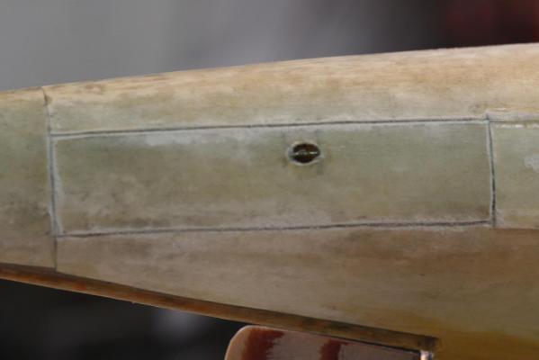
Hello all, @ Paul, copper sheet for prop blades. Sounds quite reasonable, if I can find some copper sheet. Frankly, I haven't really looked for it yet. I have some nice brass, more difficult to form though . We'll see what I can find, copper is the preferred material for ease of handling. As mentioned in my previous post the re-cementing of the port dive vane went rather smooth and quick. Okay, now what to do? I figured to start indicating the mine tube loading doors on the port side. I made a template from card stock and drew the outlines on top of the center ballast tanks. With my trusty #11 exacto knife I carefully cut into the fake steel plates. After one try I had to sharpen the blade, it was tearing the paper instead of cutting. I have a super fine sharpening stone and oh boy does it cut nice. I cut two slanted parallel cuts separated only by a fraction of 1 mm and removed a sliver of paper to indicate a very narrow groove. Once this is filled with some more poly urethane and then paint it should be enough to show the location of these lids. I also added the center bar in the torpedo bow and stern door handholds or whatever they are and picked again at the seams of all the plates, I guess this'll be an ongoing project till I'm quite satisfied with the finish before I paint the finish coats of paint on. I suppose that tomorrow I'll do the starboard side and then put on another coat of poly to let it dry overnight, ready for another sanding with fine sandpaper. I'm slowly running out of things to do below the deck line, then it's on to the con and everything above the deck, hurray I have an appointment with the Mac store Friday morning to get my iMac fixed. It's 3/4 of an hour drive to Jacksonville (JAX as the 3 letter identifier in airplane talk) and there may not be enough time for work on the sub. I already miss my iMac Just to reduce the size of the photo I had to search for how to do that on this HP laptop. Okay, I took one photo of the mine loading doors an hope you can make it out. This is hand-cut by following the pencil line and who said that "old" people don't have steady hands Cheers,
-
Thanks everyone for your likes and kind words, REALLY appreciate it. Fixed the minor inconvenience with the port dive plane Was done in about half an hour! Cleaned it up and used 1 minute epoxy cement, well - - - the tubes say 5 minutes but after I mix the required amounts it seems I have only one minute. In any case, it works and the side brackets are now also permanently cemented in and checked for level. Used slow curing epoxy this time to give me the time to fiddle with it to make sure they are level. While I was waiting for the cement to cure I proceeded to carve the outlines on the ballast tanks for the mine tubes. Could only do the port side. Pix will follow this evening because I have to get my iMac fixed. I need to call the Apple store in JAX for an appointment and that in itself is a daunting task, at least for me. I'm using my HP Pavilion laptop for the time being. Thanks again folks and cheers to all,
-
Hoi Adriaan, What kind of magnets did you use and how thick are they? There is flexible magnet sheet available of 1 mm thickness and you'll need very thin iron sheet, like from a tin can, on the other side, assuming under your deck. All this takes very little space and you can place as much or as little in strategic locations. We have some of them with pictures stuck on the fridge door, sticks pretty good. There is another method I call "slide and lock." One end works like tongue in groove and the other end should have something to lock the deck in place, which can be a piece of deck furniture. It's real simple and works like a charm. But that may get too involved to your liking. Cheers,
- 1,038 replies
-
- 1
-
-
- King of the Mississippi
- Artesania Latina
- (and 1 more)
-
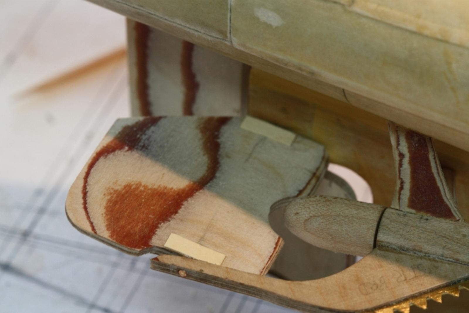
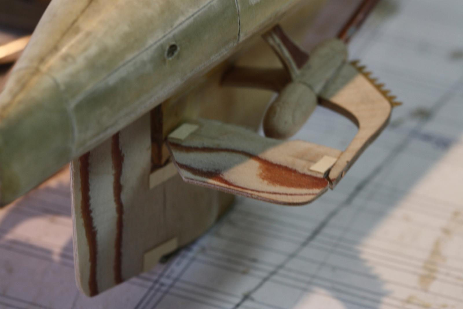
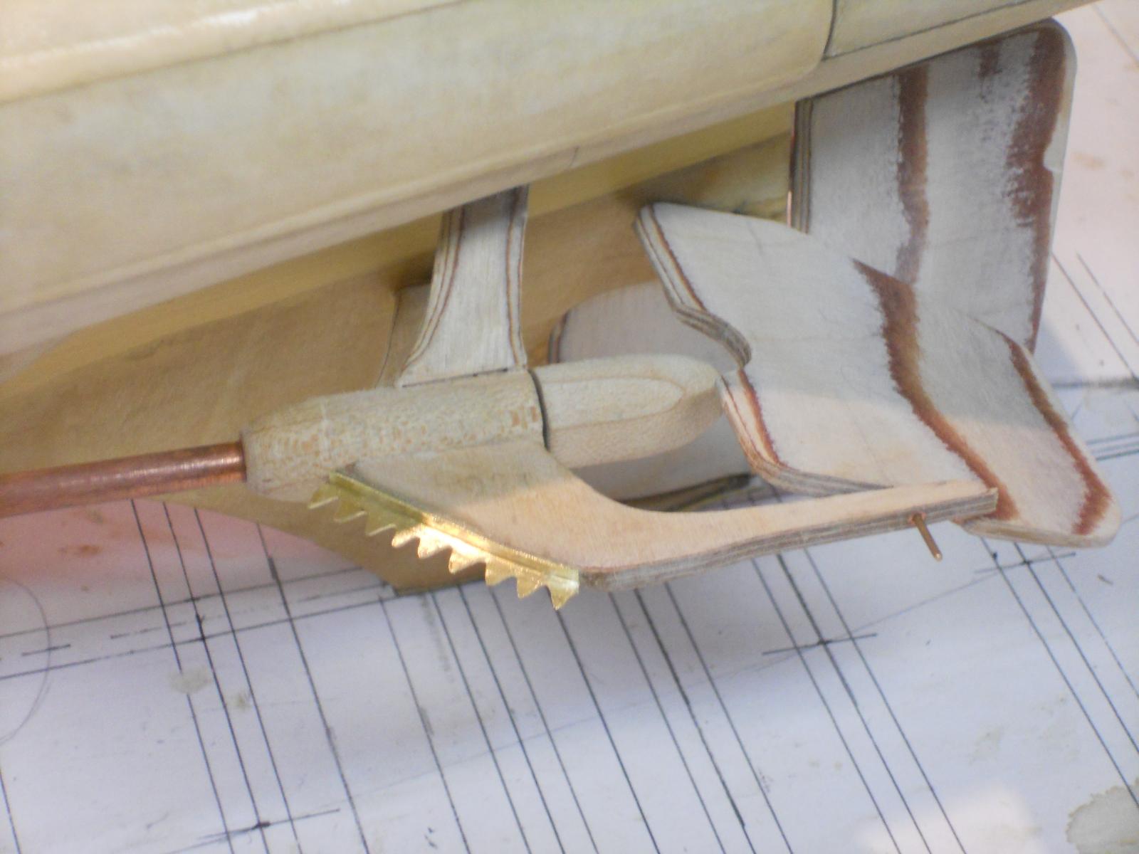
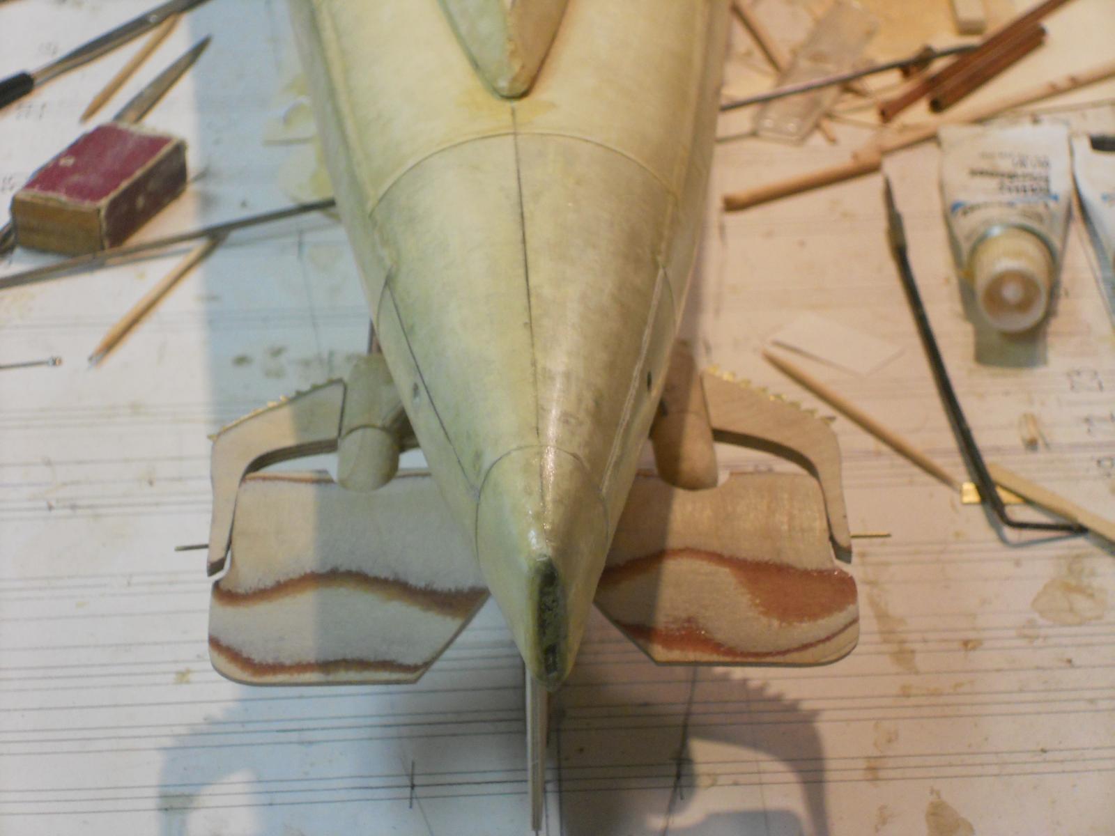
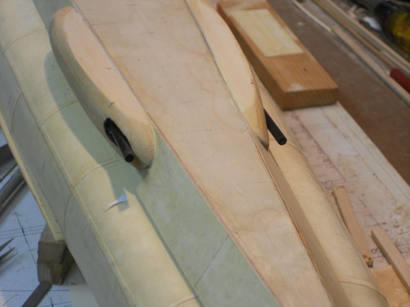
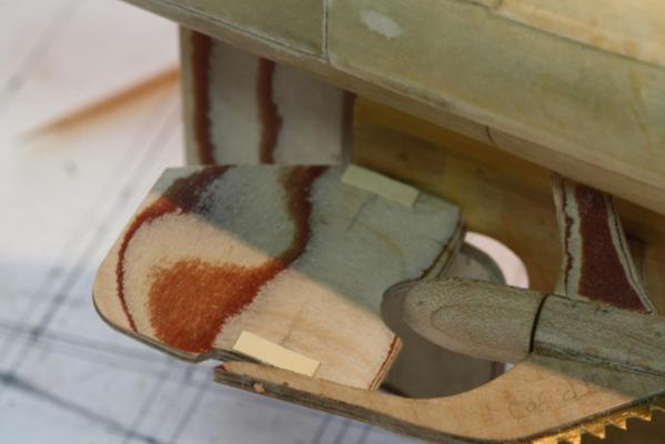
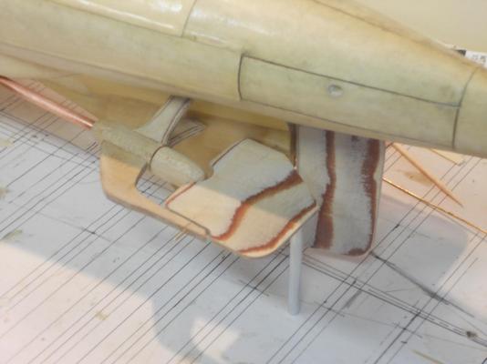
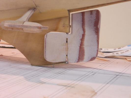
Hello all y'all, Today was a little frustrating with a minor setback I tried the cemented dive planes but the port side is not secure on the inboard hinge pin. Soooooooh - - - I'll have to redo that one again. I even put some anti seize compound on the pin going through the keel and on the ends of the bushings to prevent the epoxy cement from sticking to it. I'll give it one more try and if that fails then I'll have to go to plan B, which is using the 1.5 mm pipe as a hinge pin. I made the net/cable cutters for the leading edges of the dive plane outboard brackets. I purposely left these un-cemented so I can still remove the dive planes. They will only be cemented in place when I am positively sure the center hinge pins are secured in the dive planes. I filled the rudder slot with wood filler and finished it off nicely. Did not use paper to cover it. I also cemented both engine exhaust pipes into the fairings. Well, I made a few pics of the problem causing dive planes anyhow and the other things mentioned above. This shows the net cutter cemented to the leading edge of the outboard dive plane hinge bracket. It's still not cemented in place yet. I used 5 minute epoxy cement, the same as I used for the inboard hinge pin. Another view of the net cutters installed and the dive planes. I painted the exhaust pipes with flat black as well as the well they come out of. An overall view of what was accomplished today. Cheers,


-
Thanks to all for the "like" votes! @ Andriaan, Popeye's suggestion on using locating pins could help if the deck is a snug fit over them. It is the simplest method, give it a try. @ John (J. Lad), thank you for your encouragement and yes, we are certainly concerned about you all "down under." @ John (texxn5), Thanks for the narrative of your long journey and it was totally our pleasure meeting you and your darling wife Diane. Looking forward seeing your build up and going again. Cheers,
-
Hoi Adriaan, good to hear from you and yes, I'm worried for you and your families house and the so many people who are effected. I'm following the news about the fires yuns are having. Am also following your builds, looking nice. Sorry about the magnet problem not working too well. Anything I can do to help solve the removable deck issue? Cheers,
-
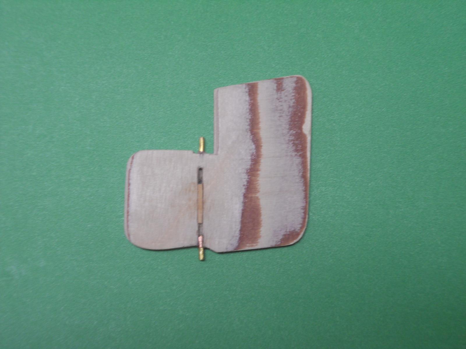
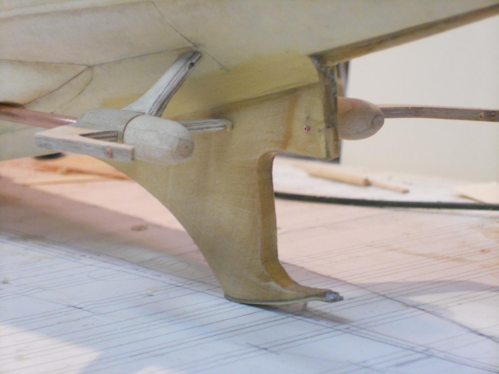
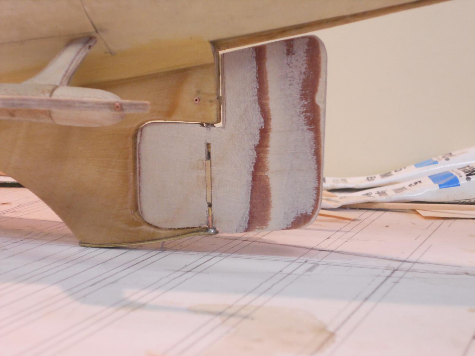
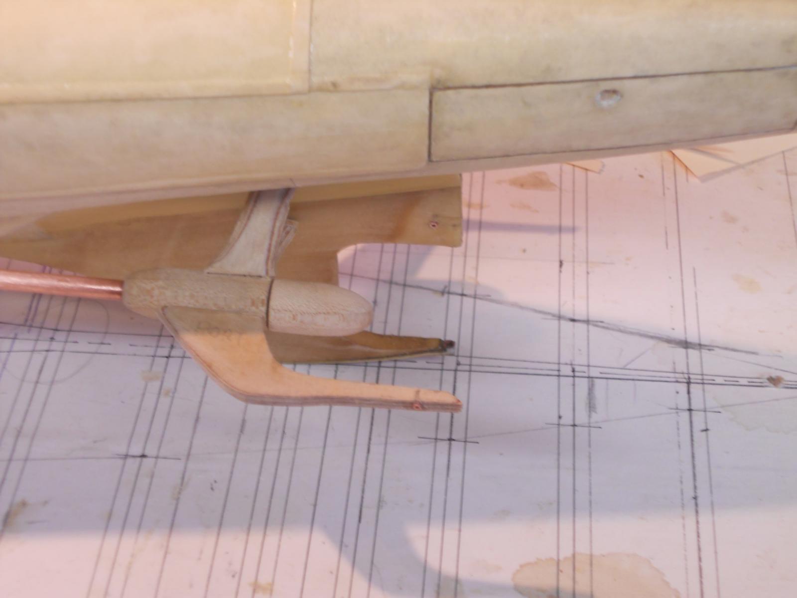
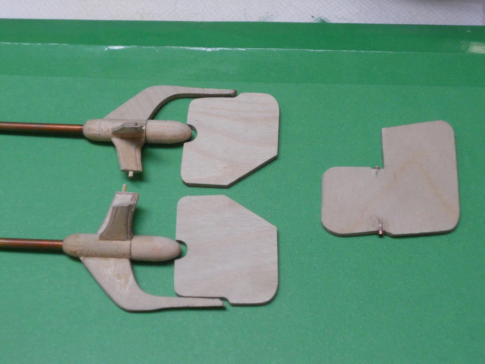
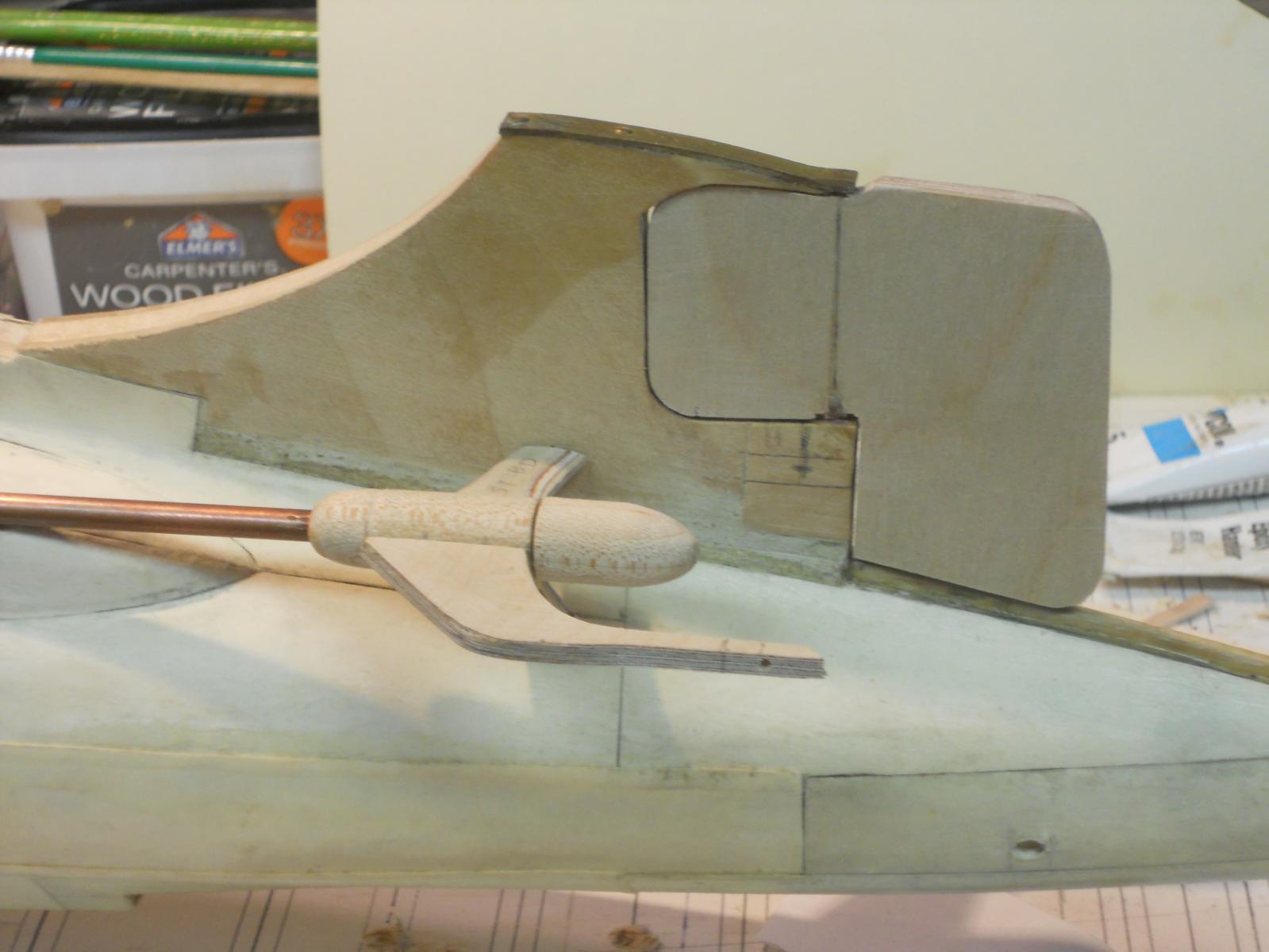
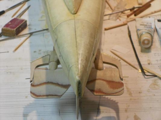
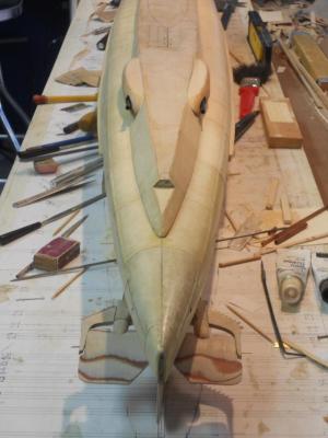
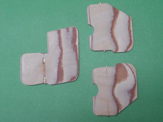
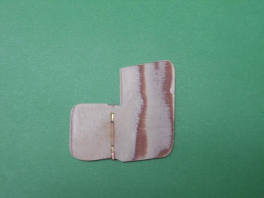
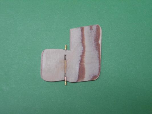
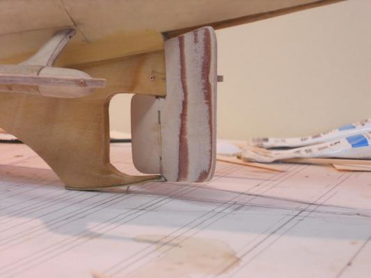
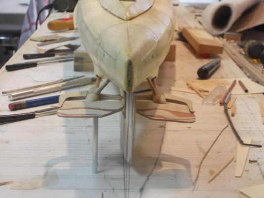
Hello everyone, and thank you all for your "like" votes! Woke up this morning at oh dark hundred due to heavy rain pounding on the roof. Hmmmm, what the hey is going on with this crazy weather anyhow. Would like to send some to Andriaan, they can certainly use a lot of it right now. Soooooh, I might as well get up and have some breakfast, ran out the front to get my newspaper and darted back in, got the coffee going and had a leisurely and quiet breakfast. I then mozied into the garage aka shipyard, and decided to jump right in and install the prop shaft assembly, rudder and dive planes. But first I had to make and install the hinge support bushings in the dive planes and the parts these hinges fit in on the boat. I used 1.5 mm copper tubing for the bushings and 0.8 mm brass pins for the hinge pins. I dry-assembled everything to locate the the hinge points on the keel and the outer dive plane support, which are also the base for the cable/net cutter that's attached to the prop shaft bearing housing. I drilled the appropriate holes in the right places and cemented small pieces of the copper tubing to the dive planes, keel and outer supports with epoxy cement. After the cement had cured I assembled everything again and had to file the copper tubes to make the dive planes fit. When I was sure that everything fit and worked I took the big step and epoxy cemented everything to the boat with a slow cure epoxy cement. This gave me the time to fiddle with it to make sure that everything was level to the waterline. The center hinge bushing goes through the vertical keel portion and the center hinge pin for the dive planes should rotate freely inside it because the pins are cemented to the inboard parts of the dive planes. I hope that the epoxy cement lives up to it's name of cementing anything to anything I also installed the rudder, which is now ready to be finished on the outside to cover the slot I had to make for the hinge pins. It works like a charm. That's where this project stands right now because I wanted to give the epoxy enough time to cure, I won't know till tomorrow whether the hinge pins are securely glued to the dive planes. In the meantime I also touched up the paint in the side launch torpedo area and I'm sure I'll find some other spots that need a touch of paint. I may ask the Admiral to put her eagle eyes on it, she is also a stickler for details Next project will be the propeller blades. I'll make them from brass sheet material of 0.9 mm. That'll be fun, trying to shape them little buggers I checked and there should be no problem in installing and removing the propeller hub with the dive planes installed. All hinge pins sit in small copper bushings, which are cemented into the rudder and both dive planes. Final fitting for length will be done when ready to assemble. I wanted metal to metal contact via the copper bushings more or less acting as bearings This shows how I solved the problem of installing the rudder because there was no other way to put the pins in on either end. This shows both pins retracted so I can slide the rudder into place between their receptacle bushings. This shows the pins pushed out as they will sit inside their receptacle bushings. Once the rudder is in place I can now fill the slot behind them and lock them in. I'll cover that side of the rudder with thin paper to finish it off. This shows the dive plane hinge receptacles in the keel and outer hinge support, also acting as the cable/net cutter brace. Here is another view of the dive plane receptacle bushings. The rudder is now installed and swings both ways nice and smooth. A little wood putty in the slots and a paper cover will finish the job, ready for paint. This shows the rudder deflected to port. Here the rudder is deflected to starboard Here the dive planes are temporarily installed as a dry-fit. All seems to be a go at this point. They are level with the water line. This is a head-on shot of the temporarily installed dive planes. I had to prop the port one up with one of the exhaust pipes Note that nothing is cemented into place yet. Cheers


-
Hello everyone from on and off sunny Florida, at least we are still having nice warm weather. To everyone who clicked on "like," thank you very much. Did not spend a lot of time in the shipyard, mowed the front lawn and after lunch I watched the US soccer team play against Australia, very nice game, US won 4 to 0. All I actually accomplished today was sanding the first two coats of poly and going over each seam with my #11 blade and a small chisel to dress it all up nice and neat. I think it's looking acceptable. Two more coats of poly should do it and then sanding again with fine sandpaper. Then paint I'll wait for the final painting till I have completed everything that'll go onto the hull so I can still remove the boat from it's build dock without worrying about the paint. Then we can leave her on the build dock and work on the topside, yeeeeah Sorry, no pics today either, perhaps tomorrow. Cheers to all,
-
Yes, Jan and it's much appreciated !!!!!!. A healthy set of teeth is crucial for our physical health. There is no restitution though for our bank account and all personal belongings the Japanese took away from us. They have given us half the peace sign about that, if you know what I mean.
-
To the many who liked my last two posts, thank you!!! @ Wacko Joe, thank you for dropping in and your kind words, really appreciate it. Sorry no pics today. I spend some time nit-picking the boat in preparation for the polyurethane coating of the entire hull. I have to finish the stern end with poly before I can proceed with installing the prop shafts and the rest of the paraphernalia in that area. So why not the rest of the boat. The entire hull is now coated with two coats of poly. It really soaked nicely into the paper and I can now start lightly sanding the hull and nit-pick again to remove some of the fuzz from the paper. Then another coat or two of poly and a light sanding to prep for the paint. I cut a groove on the hinge lineof the rudder and put two brass rods in the previously installed copper tubes. These pins can now be pushed into the hinge pin receptacles in the keel and locked into place with either epoxy cement or just filling the groove with wood putty. Then the rudder will be covered with paper to close the groove. I think this is the simplest way to make the hinges work without any evidence from the outside. I also shaped both dive dive planes and the rudder to look more streamlined. Making the dive plane hinges is still a head-scratcher for now. I need to think about whether to make the propellers removable or not. They will be able to rotate though. If I want to remove the props I can do that by not cementing the hub to the shaft and with the dive plane moved up or down there may be enough space to remove the hub. I don't know yet if this'll work other wise everything will be fixed in place but with the props being able to rotate and the dive planes also movable. I'll make some close-up pics to show what I'm talking about. I also lucked out with the position of the prop shaft assembly. With the added file folder card as simulated steel plating they seem to fit just about right, parallel to the water line and vertically to the centerline of the boat. Well, this is it for today, I'm taking tomorrow off for a day of rest. We'll continue with the build and a few pics Sunday. Cheers to all,
-
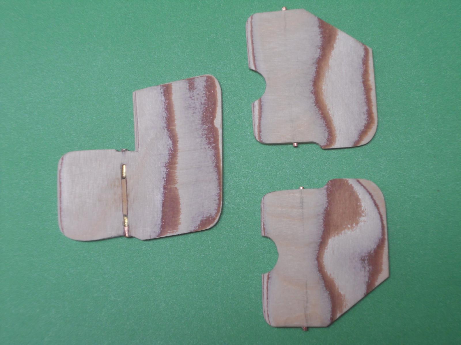
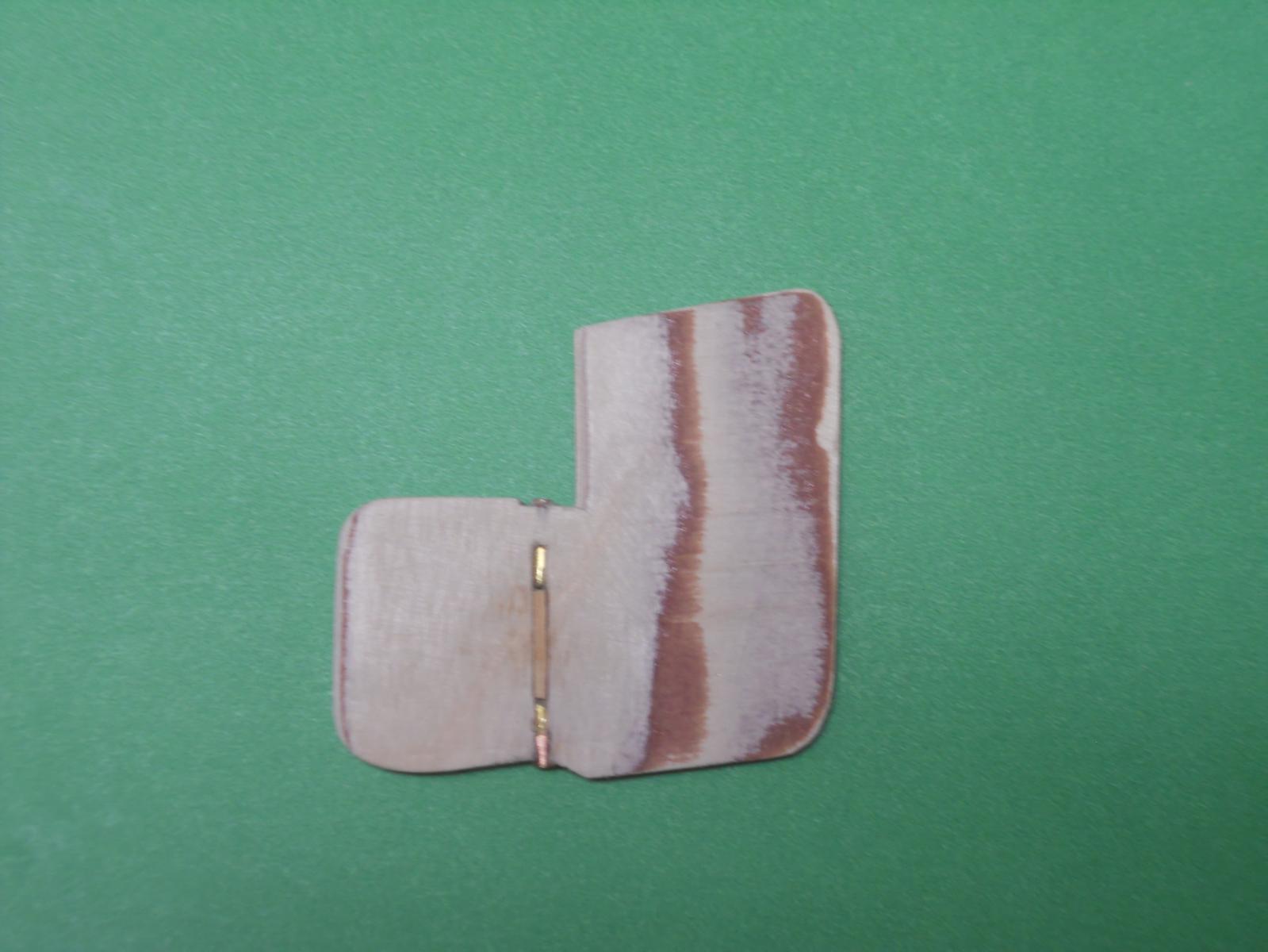
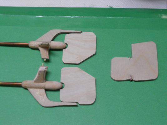
Hello friends, after my return from the dentist's office and after a light lunch of soup and yogurt I ventured back into the the garage aka shipyard. I took the glued up dive planes and rudder out of the clamps and shaved them to close to the correct size. The final shaping and sizing will be done on the boat. I started with the rudder and installed two small pieces of copper tubing to support the hinge pin and act as bearings. This can be seen in the first pic. I did manage to drill a 1.3 mm hole through the rudder for the brass hinge rod but changed my mind in how to hinge the rudder. I'll make two slits on the side instead, to install small pieces of rod as hinge pins, which will be epoxy cemented in. I'll cover the pin centerline with strips of wood, actually kinda made into half-rouns or half ovals. Needles to say that this must be done when everything else in that area is completed. I also started with the installation of the dive planes. This too will get the copper tube treatment for the hinges. I am using 1.2 mm brass rod for all the hinges. The rudder and dive planes still need to be shaped like an airfoil. I still need to shorten the propeller hubs a little because they stick into cutouts of the dive planes and I want to be able to install the props after the propeller shaft support structure is mounted to the hull and the dive planes are in the way. It's now a matter of noting the sequence of assembly before I run into a snag and have to tear things apart - - - again Here are two pics I took this afternoon. the port and starboard dive planes shaped to my sketch. Final shaping will have to be done on the boat but that requires that I also permanently install the propeller shaft assembly, which requires that they must be perfectly horizontal. After I epoxied the two small copper tubes in I carefully and slowly filed them down so that rudder fits snug between the copper tubes I already installed into the keel. Still needs a lot of work as noted above. Cheers,

-
Thank you everyone for the "like" votes, really appreciated! Re the dentist, there is a history behind it that ties in with the O 19 model. Allow me to explain: a few years ago the Dutch Government passed a law to offer a restoration for physical and mental damage people incurred during the Japanese occupation of the Netherlands east indies and the incarceration of its citizens. My wife and I applied and we both send in about seven problems. My wife's requests were denied and I was only offered one, the restoration of my mouth. Due to severe malnutrition and debilitating tropical diseases my bones and brain took the greatest hit. Ergo - - - teeth problems and some brain damage. So, I am now in the final phase of my dental restoration of $30.000 paid for by the Netherlands's Government. That's the reason for my excitement, to have a full set of teeth again with added bone in my jaws. My apologies for my long sob story. Today's dental project took 2 and a half hours and all went extremely well, no pain yet in the jaw, even with an inch and quarter cut in the gums @ Ian, my dentist and I have become good friends and yes, he has given me a whole bunch of nice tools, including scalpels. @ Popeye, thanks for your kind words and sorry to hear about your bad experiences with dentists. I have lucked out with some very good ones. @ John - texxn5, Good to hear from you and your kind words. Good for you finding some Leffe blond, good stuff. Take care and stay safe on your travels. @ Frank, thank you for visiting my shipyard and your kind words. Yes, this build has special meaning to me and she is more then half way completed. I'm also looking forward to seeing her as my father saw her. Come and stop by again. Cheers to all,