HOLIDAY DONATION DRIVE - SUPPORT MSW - DO YOUR PART TO KEEP THIS GREAT FORUM GOING! (83 donations so far out of 49,000 members - C'mon guys!)
×


Piet
-
Posts
3,568 -
Joined
-
Last visited
Content Type
Profiles
Forums
Gallery
Events
Everything posted by Piet
-
 Yeah, sometimes we get wrapped around the axle about details that may not really be known at this day and age. Glad you went ahead with your gut-feeling. That's a mighty fine knee beam you got there, looks nice and crisp. It helps using good lumber. Cheers,
 -
Wow, great progress. I like the detail in doors, windows and handrail. Really neat work. Cheers,
-
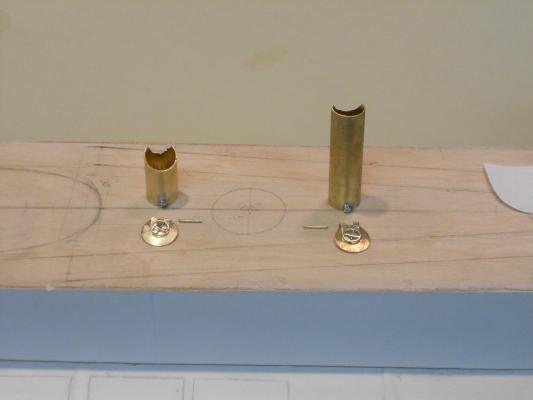
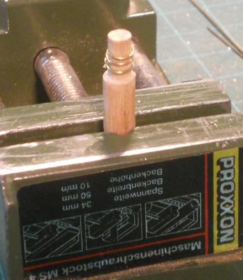
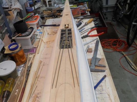
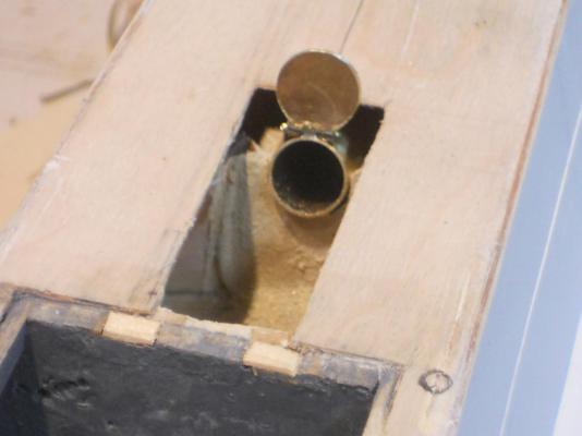
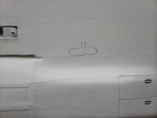
Hello every one. Been busy making the torp loading tube door locking wheels. I turned a wooden dowel to the correct diameter and then wound a .7 mm brass rod around it to form a coil. That way I could cut a pice that's circularly formed. Okay, now I have the rim of 10.5 mm. Next I cut a few small pieces of the same diameter rod for the spokes and soldered them into a cross. I cut and filed the ends to fit inside the rim and soldered it all together. Yes, I used the steel office clamp as a heat-sink. Filed and scraped excess solder away but the photo tells me I need to do some cleaning up. I also made the hinges for the read pressure door and now both tubes are ready for assembling and paint. I also cut and installed the small pieces of wood for under the deck plates at the stern torp loading well for the hatch door hinges. When that is all nicely trimmed both the bow and stern wells are ready for paint and installation of the tubes. Then it's making busy with the hatch door hinges. It's amazing how much time goes into making these small items. Well, here are two pics of today's accomplishments. Here we have both the bow and stern torpedo loading tube assemblies displayed on to of the deck. In the meantime I have painted the inside of the tubes flat black That penciled circle between the tubes is the future location for the deck gun. This shows the result of winding the brass rod to make the little wheel rims. Cheers,
-
Thank you Daniel, John and Sjors for dropping in and your comments, I think @ John, no, I'm not psychic but I remembered you asking about it when you visited us Well, right now I really don't know yet. I have to figure out how they did it. I can probably make some workable system that would suffice, but it would be great if I could find the real thing. I know there are drawings in the Naval Archive but accessing them for this may be too much to wish for. I'm sure I can figure something out. @ Sjors, I have no problem finding the boat my friend. She is pinned to my build dock, which I can move around and rotate. All that "stuff" on the build board is what I use on a daily base and am just too lazy to put it away and then retrieving it again the next day. I have more tools and "stuff" to the right of the dock that I also use often, it's handy. There is "stuff" behind it against the wall but that's still from where I put things before the build. Just too lazy to put it somewhere else. At least I know where everything is Gwen, the Admiral, already told me, you used to be such a neat freak with your tools and work area, what happened???? I don't know - - - I guess I am slowly sliding into the slob abyss - - - oh noooooo - - -
-
Ooooooh, that looks really nice John! Great progress you are making and nice colors too, matches the real ship. And I just had a glass of wine before going to bed. had a beer before dinner though Cheers,
- 2,250 replies
-
- 1
-

-
- model shipways
- Charles W Morgan
- (and 1 more)
-
Hello Paul and John, sorry, almost overlooked yuns, you were on the next page, fooled me. @ John (texxn5), well yes, these doors needed to close all openings to the pressure hull and to withstand the pressure they needed be convex to the outside. the same applies to the escape tubes and the AA gun mount supports. The AA guns on the O 19 retract inside a watertight tube with a pressure lid to close it. Pretty clever. Next you are going to ask me if I'm going to make that workable. Go ahead and ask - - - well, I was thinking about it but right now I'm not so sure. @ Paul, thanks for dropping my friend and your kind and supporting words. Yes, I'm well pleased with how she is coming along. Still a lot of time consuming detail work ahead though. Cheers,
-
Hello everyone, and thanks to Yambo,John (texxxn5) and Sjors for dropping in. Well, today I made the brass rails and support pieces for over the launcher deck area. I also completed the mounting block for the stern torpedo loading tube and installed same. I'm now ready to finish the well opening and add a few strips of wood for the hatch door hinges and paint the inside of the forward and rear well areas. Hope I have enough paint. Then I cut three small pieces of tubing for the pressure door and soldered the one to the tube. Next I tried to make the door locking wheel but had some problems with it. Very small to work with but I'm not giving up. I need to have them finished before I can solder the hinges to the door. I'm still waiting on the 17 mm brass tubes for the escape hatch tubes. I like to have them before I can definitely know where the deck rails go. This too will be a tedious job to cement them to the deck. But there is still a lot of work to do before I can do that. Here are two pics of some of the things I did today. These are the brass real and deck support beams/rails over the launcher deck area. The two forward ones are for the deck support, the four behind them are for deck support on the outboard side and hatch covers between the rails.. Then I cut 4 pieces of N scale flex track for the rails on the existing deck. These rails actually are the tops of the torpedo tube alley structure for loading the deck torpedo launcher. They used a small four wheel trolly to bring the torpedoes forward to the loading gantry. If you squint real good you may be able to see the four hatch doors for the loading tube well next to the well opening. This shows the mounting block for the stern loading tube. Cheers,
-
Hey Mark, you just made my day! But wait, no fun to use my slagomatic without an audience and don't have a video camera This is a great fun video, thanks for sharing, now I know where your interests lay Cheers,
-
Sorry Mark and Popeye, don't want to ignore yuns. Your posts came in as I was bury packing at the keyboard. @ Mark, that you very much for your kind words, I'm exited about the progress. And yes, my lawn looks okay. I fed it a few weeks ago and with all the rain it's nice and green. The back yard too! @ Popeye, wait till it's in color!! I can't wait myself but I need to have patience though, I don't want to damage the finishing paint. Am waiting for the deck anchor answer - - - - Now you got me with "the Gallagher" action. If I know what it is then may I can also find peaceful satisfaction Cheers,
-
Hello everyone and thanks for stopping by and clicking "like." I like likes @ John (Lad), thank you John. @ Boris, thank you and I have not forgotten you, hope you are oaky. @ Remco, how did you figure I was pondering on making the closing and locking thingy? Yes, and I should have made and installed that before I put the hinges on. Hmmm, now I have to see of my heat-sink will work, again. The scale is still pretty small for that kind of detailing, even at 1:50. Did you know that on the USS Cod there was a bunk below the loading tube? I guess there was an incentive to make sure it didn't leak @ Daniel, you are welcome. It's my tool and die maker certification from eons ago that surfaces so now and then. If you have to make a lot of parts it's best to use steel. For my purposes hard oak with brass or copper will work just fine. It has a tendency for some waste though but being a cheep Dutchman I found a way around that, I hammered the edges into shape before trimming Well, today produced little progress. Most of my time was spend figuring out how to install the "rails" for the torpedo tunnels and those going over the deck launcher. I had to move the escape hatch tunnel just aft of the launcher a little more aft because it interfered with the run of the "rails". So I had to plug the hole I already made, which was a little challenge but came out just fine due to lack of access. It'll be hardly noticeable or not at all when the mahogany deck slats are in place. This was not the only destruction I had to do. i also had to remove the center of the deck"bulkhead" where the aft torpedo loading tube will be. That area is exposed for view with the doors open and the space below the deck is pretty empty. Then I made a block to rest the tube on which is still not finished. Note to self, make the closing and locking thingy for the pressure lid at the same time I'm soldering the hinges. I also made the four little doors that close off the forward loading tube well but they too are not finished. Some small details on the bottom side and the hinges. What else, oh yea, I have not found any picture yet how that side bow anchor looks like. It could very well be a small mushroom anchor with a swivel stock. I also have no idea if there is a door to enclose the anchor or that the convex side of the anchor kinda kinda closes it's well. If there is a door it would most likely be hydraulically operated. I think I have seen a very poor picture of the door and kinda know how it looks like. The easy way out is to just make the door shape from a piece of bass wood and glue it in place That way I can paint the boat. I have purchased the paint The red I planned to use is too red. According to a color photo of a model made by the boot builder shows it to be more like "red lead." It's an orangy rusty color. I found a nice compromise paint, very close. I also got a good match for the green and the light gray for the top works. I'm a happy camper, baby I was going to order a ¾ inch brass tube for the AA gun placement but they wanted $25 for shipping for a #10 tube. I told them to shove it. So, I picked up a small sheet of 1.5 mm brass and I'm going to make my own tube, so there - - - grumble grumble There is nothing like scratch building eh? Okay, that's it for today. Tomorrow is rear torp loading tube time. More "priegel werk" as the Dutch would say. Hmmmm, my Dutch English dictionary doesn't have an English word for that, could be minute / tedious work. All y'all have a great day and please come and visit anytime, beer and popcorn is always ready Cheers,
-
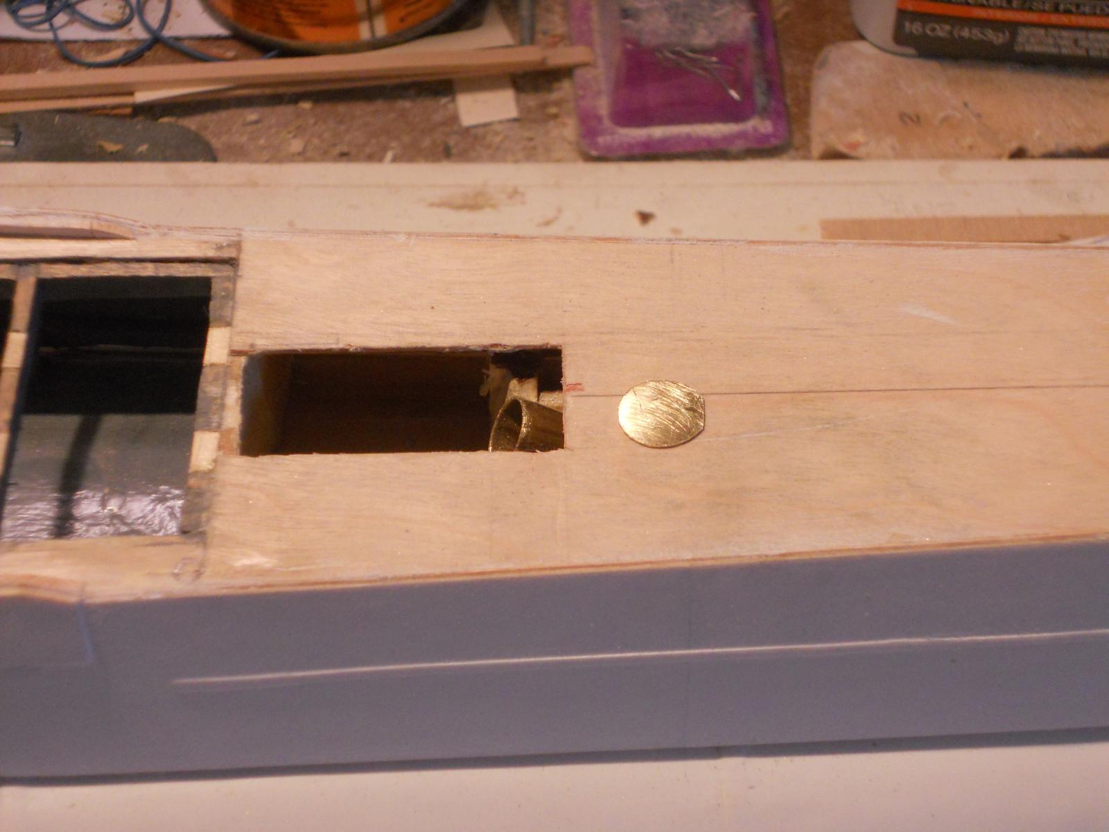
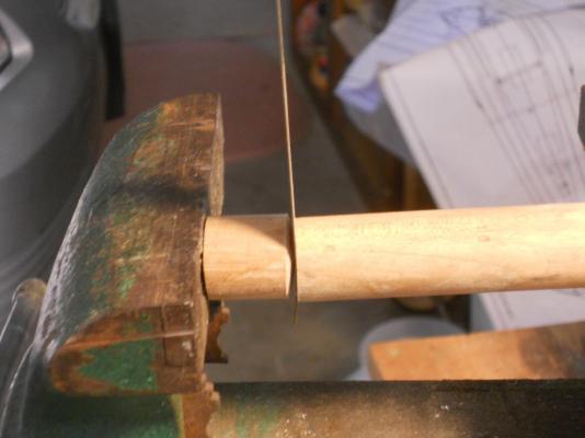
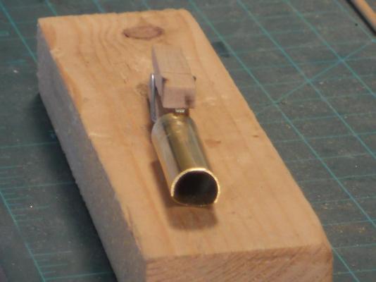
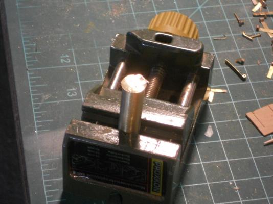
Today was nice and sunny and planned to mow the front lawn after it had dried. This gave me some time to do some more tedious work on the sub. I decided to make the pressure door for the forward torpedo loading tube and hopefully install the door on it. I cut the 10 mm brass tube to size and cleaned it. Then cut 3 each 3 mm pieces of 1.5 mm brass tubing for the hinge of the pressure door. In order to make the door concave/convex I made a forming die from an oak dowel. Made one end hollow and an other piece rounded to fit inside the hollowed out one. Then put a .3 mm thick piece of brass sheet stock in between and put this all in my bench vice and squeezed the living daylights out of it. It worked great! Next I had to cut some .15 brass shim stock into 2.5 mm wide strips for the door hinge pieces. They were soldered to the outside of the door leaving a gap for the center hinge piece on the tube. I clamped these with a small wooden clothes pin. Then bend the ends 90 degrees backwards and soldered the small pieces of tubing to it. I used a steel office clamp as a heat sink so as not to desolder the strips from the door. A little fine-tuning with a small drill bit and the door swings open and closed. I'm now ready to clean and paint this little bugger and cement it in place. But first I have to glue a few small strips of wood to the underside of the deck for the hinges of the hinged access doors. Hmmmm, maybe I'll make them also from brass tubing and shim stock. I'll decrease the wall thickness of the brass tube a little as I did for the torpedo tube then it's not too bulky. Still a lot of work ahead with all this small work but this way it'll look better and realistic. It's now just a matter how small can I make these things without tearing my hair out, the little I still have Well, that's about all I did today and not to forget, mowing the front lawn !! These are oak dowels, the tall one is concave and the short one is convex. It's difficult to see here. Here I and posing the process, when I'm actually doing the pressing it'll be better positioned. After a lot of filing to make a good fit I am posing the finished door. I did use a small hammer to form finish the edges. It's now ready to receive the hinges. The loading tube is cut to size and the completed pressure door is placed on the deck. I used a small wooden clothes pin to hold the small hinge tube in place. The door hinge tubes are soldered to the brass shim stock. The steel office clamp acts as a heat sink. The completed assembly posing with the door closed. The completed assembly posing with the door open. Here I just stuck the completed loading tube into it's location to check for fit. I had to remove it for the additional work to the opening. Yes, it needs to be cleaned and all the dust removed and then painted. i had to some more grinding to position the tube better. Cheers,


-
Thanks everyone for your "like" votes. it's much appreciated. @ Mark, thank you very much for your encouraging words, I'm glad you approve my progress. Well yes, perhaps smashing the confuser to smithereens may feel good but that doesn't fix it. This reminds me though that when I was the director of QC and Engineering for an airline. The electric typewriter of my secretary really gave her a lot of trouble to the point that she couldn't keep up with the work. So, I told the CEO that if I didn't get a new one right now it was going to have an accident. I had it already at the top of the stairs to the hangar to bring it to the repair shop - - - - - - NOT ! Well, I lost my balance (har, har), and not to injure myself I had to let go of the typewriter, so sorry - - - NOT Half hour later I got a new typewriter. Cheers,
-
Sweeeeeeet !!!! Looking nice Adriaan. Cheers,
-
Hello everyone and thanks for dropping in. @ John (texxn5), glad you appreciate the pics, it's something different from Sjors' cotton cannon balls, muskets and pikes Still thinking about making one to show @ John (Lad), thanks your kind words and yes, we need to use the magnifier and clean them fuzzies up before the finish coat. @ Remco, thans for leading me to Paul's suggestion, that's where I read it. Me "stomkop" so forgetful Yes, it would certainly be a great addition but I can see a bill of over one hundred smakkers for rivets and on a smallish Government pension we must be careful with expenditures, unfortunately. Thinking how to arrange it, print some money?? Heck, the Federal Reserve does it - - - oh no - - - now the NSA will be at my door @ Adriaan, thank you my friend and so does you GF, good progress. Cheers,
-
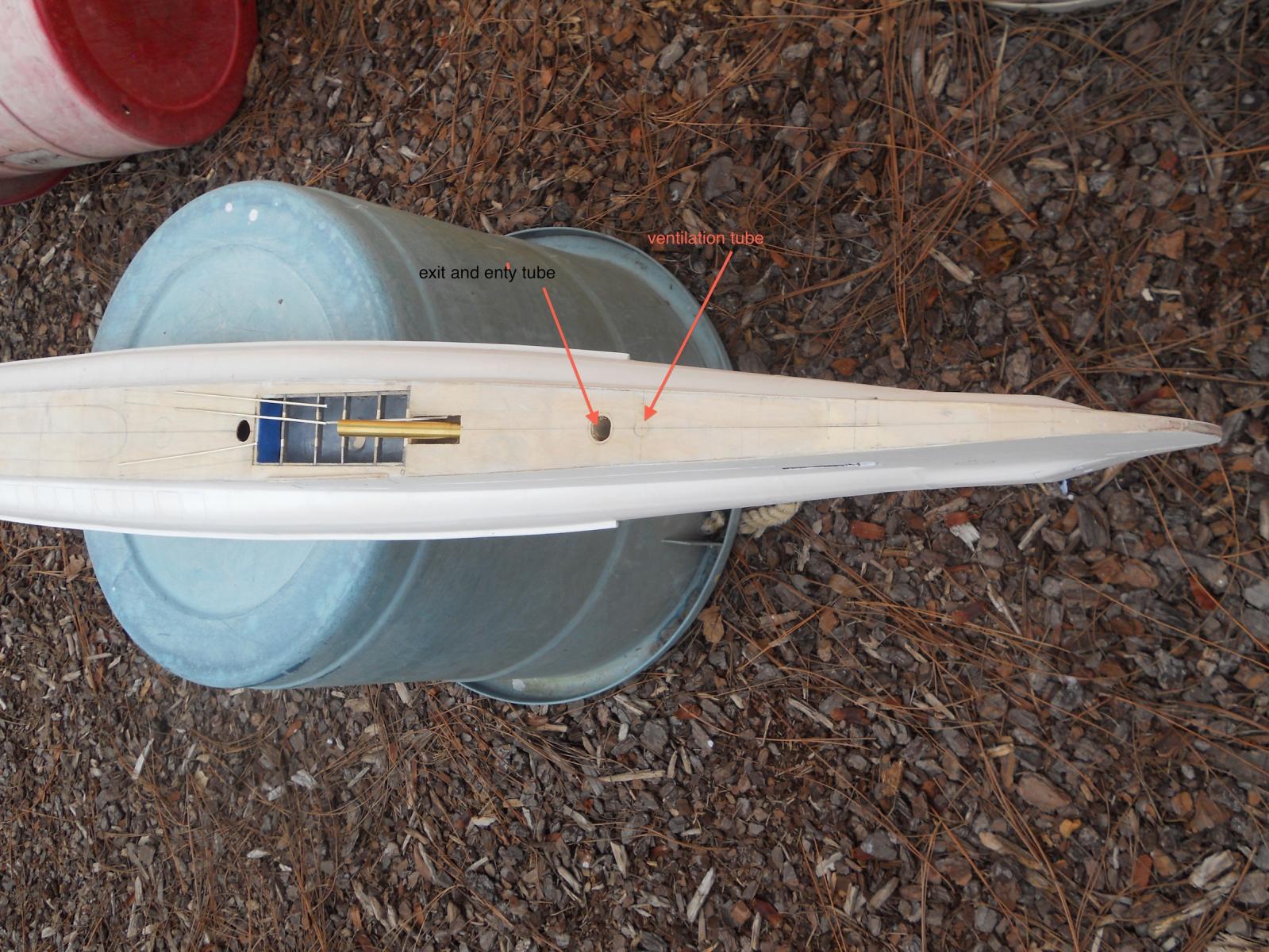
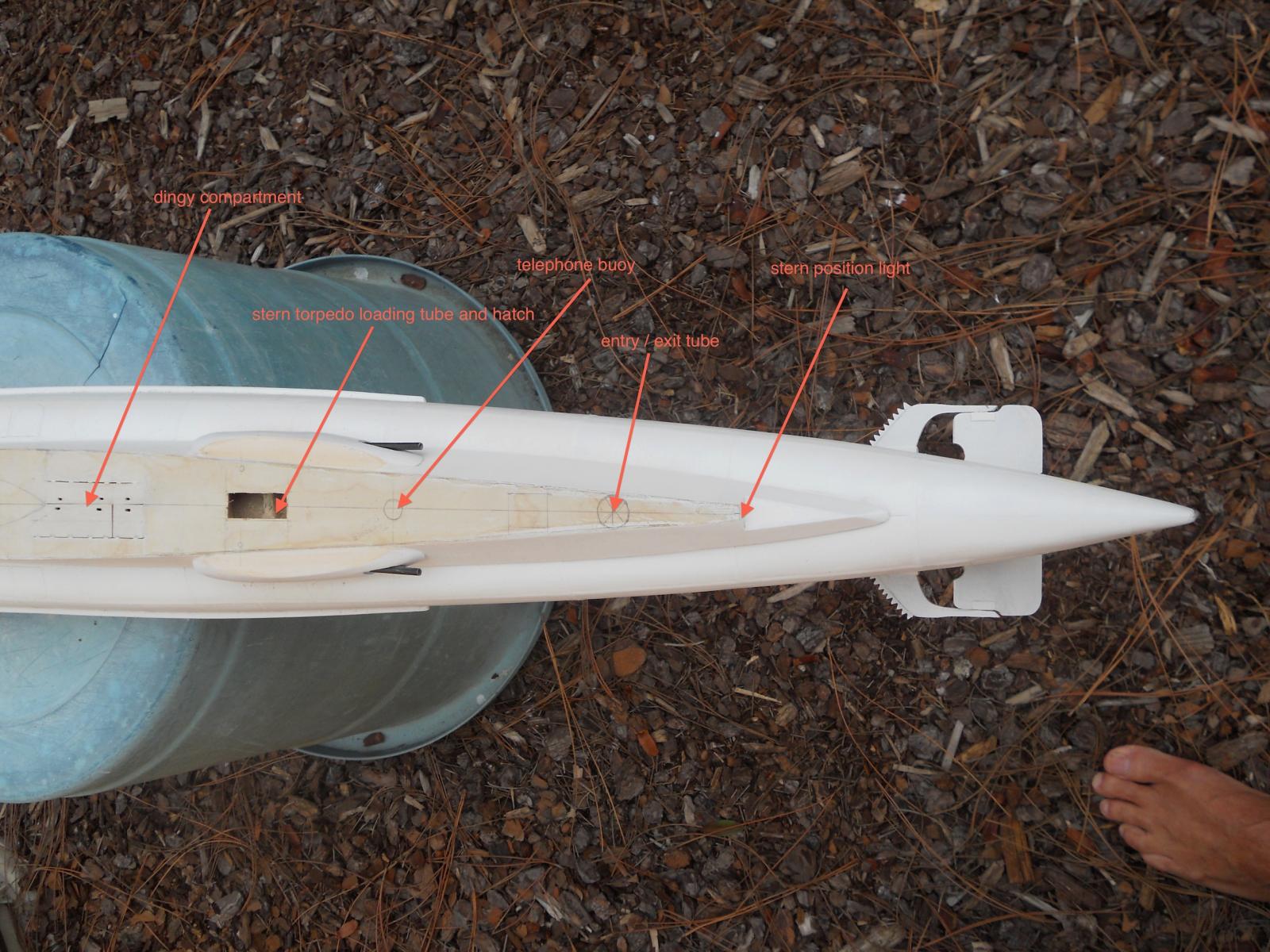
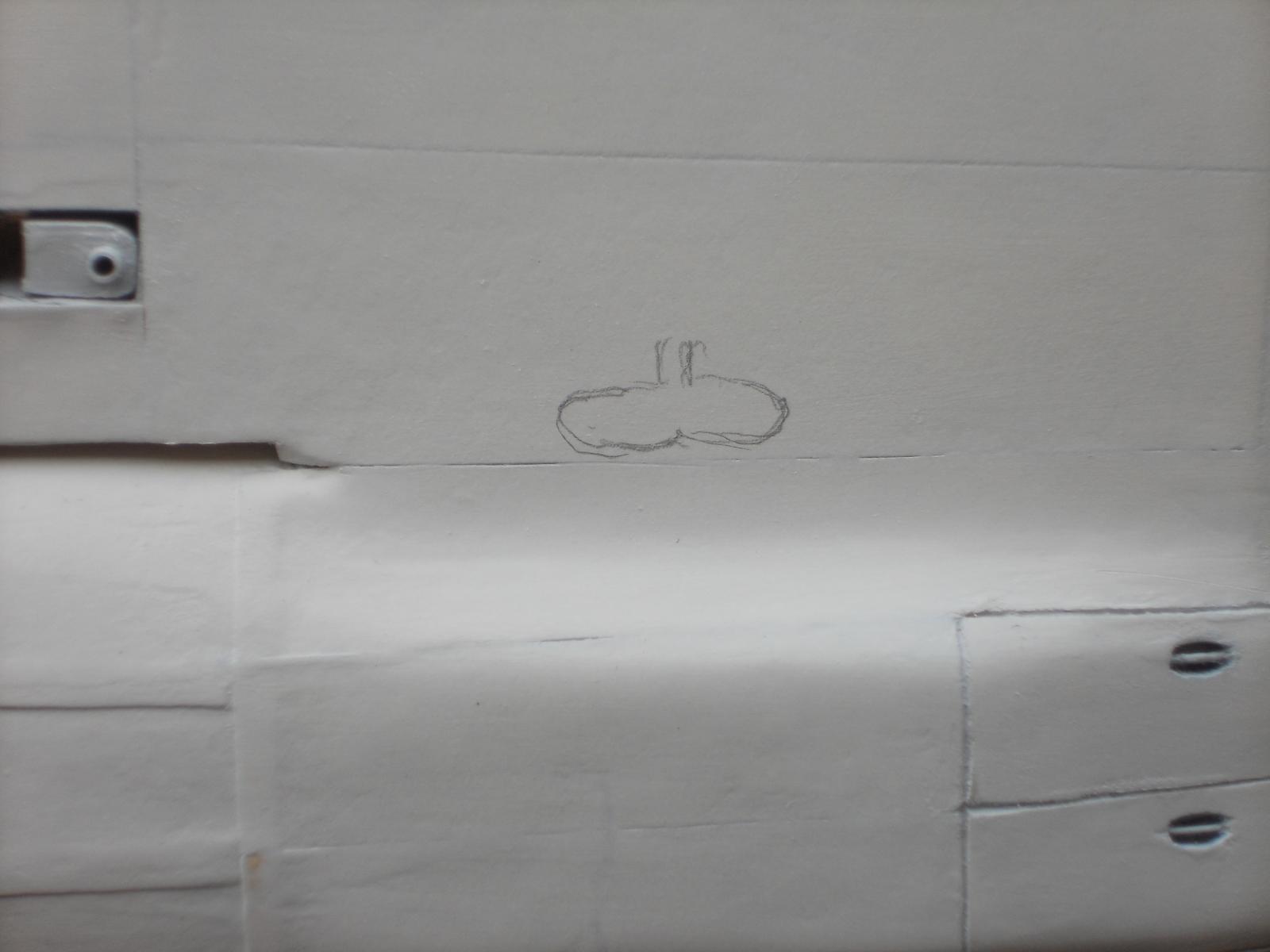
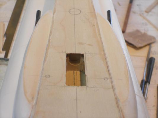
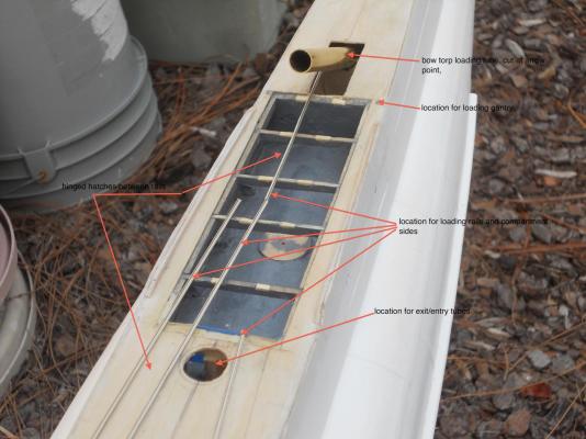
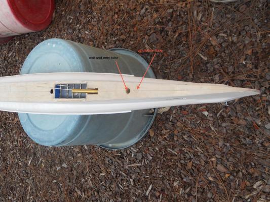
Today I started with the bow torpedo loading tube. I cut a hole in the forward deck for the hinged hatches and ground a space out for the brass tube and added some more wood behind it for better support. I also pre-cut the holes for the escape and entry tubes in the fore deck. Then I proceeded to the aft deck and cut the rectangular hole for the stern torpedo loading tube but have not made any further provisions to secure the tube. The stern escape / entry tube is located and marked on the deck but have not cut the hole for it, yet. The edges are just inside the side deck plates and that concerns me a little, however, according to the drawings and photos that's about right. As noted on one of my previous posts, I have to rework the deck area above the side launch torpedoes. This brings a lot more work but it's according to the deck layout drawing and I should have paid more attention to it before doing it my way (sorry Frank Sinatra ) Oh, I really don't mind it though, I learned a few things in the meantime. With all those hinged hatches between the "tracks" I'll most likely only make the ones above the side launch torpedo launcher. The rest will be indicated as I'll do with some other hatches on the deck. Okay, that's about it for today and I took a few shots of what was done. This is a shot from the future conning tower of the forward deck area. I have annotated the particular items of interest. I have just stuck a piece of 10 mm brass tube in it's semi prepped location and it still needs to be cut to the right size. Then it needs the hinges soldered to it and a lid must be made also with hinges. I also need to add small planks of wood for the hatch hinges. There are two pairs and these will fold outboard. This is another view of the forward deck with annotations. I have just laid the "rails" loosely on the deck to where they are to go. This is where we are today on the rear deck. I have to make a block to support the brass loading tube which will then be glued to the top of the pressure hull. Here too, I'll have to glue in a few strips of wood under the deck for the hatch hinges. I just drew the outline of the future side mounted anchor. I'll make that one when I receive the soft copper Paul so graciously is sending to me. This'll be a fun little model. Couldn't resist making a close-up of the stern area to show how nice it turned out. In looking at the pic I see that I still need to clean up a few things, still a few "fuzzies." Cheers,

-
Thanks everyone for visiting and clicking "like," it's much appreciated! @ John (texxn5), yeah, I remember discussing it (the mines) some when you and Di stopped by. Actually it's not permanently shelved though I'll leave it on the shelf as a possible future project even after it's all painted. I can work very carefully around it and touch up any area that may gets scratched. @ John (Lad), yes indeed, they had a lot of stuff below decks. Just because these subs had external torpedo tubes, also located below decks, they needed a system to load them as well as carrying spares. The area below decks, which is actually an area between the top of the pressure hull and the top of the deck, is a wasted area so they utilized it as much as possible. @ Andy, wow, yes, that's a possibility! Thanks for the links, it also reminded me of having read about these decals some time ago in another build. They are rather costly and for the amount of rivets I'll be spending a fortune on it. I'll have to see how how many sheets I would need if I go that route. Very tempting !!!! Cheers,
-
Hey John, is that nice looking moos scull on post 811 your figurehead for the Morgan???? Just asking you know Cheers with a Leffe
- 2,250 replies
-
- 1
-
-
- model shipways
- Charles W Morgan
- (and 1 more)
-
Okay, let's start with @ John (texxxn5), Thanks John and yes, I did hoist a nice cold Belgian Palm beer for the occasion. I'm glad you found some good Belgian ale, "proost" as they say in Holland. @ Remco, thank you my friend and I almost twisted my arm by patting myself on the back Yes, I am well pleased with the results. BTW, the Java drawings and brass tubes arrived to day Awesome! Will follow up with a PM from the iMac. @ John (Lad), yup, it certainly is hiding that ugly tan and smudged look. I wish all y'all could see it in real "life." @ Sjors, hey, you pay for the plane tickets and I'll come on over in a flash. Just have a bed and grub available and I'll paint your whole house BTW, your BIG ship model looks awesome! @ Anthony, thank you for the kudos and I did indeed imbibe in a nice Belgian beer, Palm. Nice and mellow. @ Popeye, what can I say, I know you are following my build and so am I following yours. - - - - -You are so right about computer woes not being funny. It's ironic how much we depend on these infernal machines in this day and age. The sledge hammer treatment works only on trucks and trains, on airplanes we use smaller hammers The old adage of "paint hides a lot of sin" does not apply in this case, it actually enhanced the look but hides that ugly tan and discolored smudges. Thanks to Yvesvidal, dvm27, Boris, Flying-Dutchman-2, Andy and Banyan for your like votes, much appreciated. Cheers to all
-
Holy Toledo - - - so many responses and likes, thank you all for your very kind words, this means a lot to me Even my dear wife, the Admiral, was impressed by how she looks. Needles to say, I am also well pleased in how she turned out. I couldn't really see how the seams and "plate" joints would look before the primer coat. The Admiral compared the model with all the pics I have taped near the dock and she can see that it's very close to the real thing. I guess it's time to get my Paasche airbrush setup hooked up again and start painting color, but don't rush me - - - -- because I also found out that, and that according to a body plan detail of one of the bow frames, that there is an additional anchor tucked inside the deck structure. Sooooooo, I'm thinking - - - - - to add that little hummer to the model. It's supposed to be visible from the outside but I have not seen it on any of the actual photos of the boat during it's construction and launch, even on later pics. It's also possible that it has a door to close-off that anchor. I need to do some more research to make sure it had a side launch anchor before I start cutting a slot in the deck side. If there is a door then I can just carve the outlines in the "side plates." I'll also check with my mentor Gino den Ridder if he is aware of this side anchor. Oh what a tangled web we weave Got a call from the computer fixit shop that my trusty iMac was ready for pickup. I had them install a 1 Tbite hard drive in it, so I should have plenty of space for ship pictures So the Admiral and I drove down to DBA to pick it up and then it was lunch time and proceeded to the Olive Garden for lunch. After that we went to Hobby Lobby to see if they had Styrene but no, so I'll go mail order. I started out this morning by measuring out the location of all the "stuff" that goes in and on the deck. Air vents, excess hatches, torpedo loading hatches, bollards etc. etc. and of course the conning tower That'll be a project all by itself. I also found that I have to make a drastic change to that small part of the deck above the deck torpedoes. Hindsight again, the deck drawings show it a little different then I had done, so I need to alter that area, which is no problem. There will be plenty of removable hatches between the loading tracks so we can see the spare torpedoes as well as the inside of the deck launcher. That means of course that I have to make a bunch of torpedoes I'll spend some time browsing through the photos I have to get some more details. I'll respond to all who posted comments to my primer picture post in the following post, Cheers to all,
-
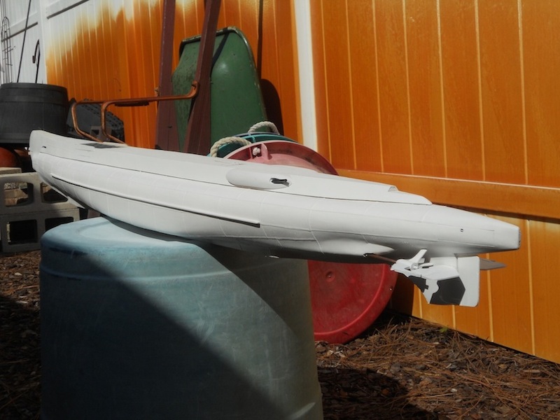
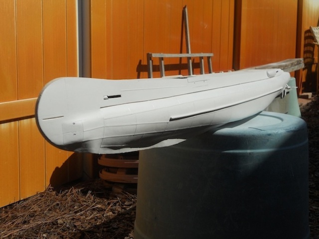
Hello everyone, again. Well, today was going to be THE day of painting the sub with an enamel primer. I used this primer before and it dries nice and hard. I took it outside next to the garage and put it on one of the Admiral's large plastic garden barrels as my paint station. Then I used my shop vac to blow all the dust off it after the sanding I gave it in the last couple of days. Then wiped her down with a damp rag with solvent. I used a primer in a "rattle" can from the local hardware store, like Krylon but dries harder. I put two coats on it and let it sit in the warm sun for a few hours. In the meantime I put the mushroom anchor back in the lathe and cut it down thinner and hollowed it out to make it into a dish shape. Then cemented the anchor post into it with 5 minute epoxy and also put an eye bolt inside the hull to hold the anchor "cable", which is just a piece of heavy black rigging line. I drilled a hole in the center false vertical keel for the anchor post and made and installed the eye bolt into one of the frames. Then fastened the anchor cable to the eye bolt and the anchor and stuffed the cable inside the hull. The anchor fits nice a snug in it's little "house" and all we see is the rounded bottom of it, quite neat to look at. The Admiral asked where the anchor was so I told her to bend down and look under the bow, ooooh, she said, I see it's bold head. Weird Dutch humor She really liked the looks of the boot now that it's painted white. I mentioned in a previous post that with the primer on it I should be able to see all the blemishes and sanded through spots, etc. Well now, this afternoon I took the boot outside and sat in my lawn chair in the shade with some 400 sandpaper and scrutinized the hull for any of that funny stuff and was pleasantly surprised how few little thingies I found that needed some attention. I did sand it down very lightly to remove some of the grittiness from the paint and it's looking really good, I am a happy camper So, I guess we can now put some color on it. I have a gallon of semi-gloss enamel called "Roasted Pepper" that we used for our front door. I love the color because it's not a fiery red but more a subdued red. It's the same paint I used for the VOC ship gunport lids. It'll be red up to the waterline and above it a forest like green, which I have not picked out yet. Well, here are two shots of the boat just painted with primer. Cheers.


-
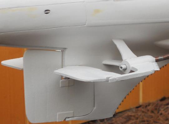
Thanks every one for visiting and your like votes. @ Recouch444, thank you for your kind words! Yes, this build has special meaning for me and brings back memories, many good but also some not so good. I am thoroughly enjoying this build though. @ Paul, again many thanks for helping me out with the copper. Fortunately I made it so that I can install and remove the prop hubs. @ John texxn5, ah yes, I remember we talked about it and I have attached a "cable" to it and it's now snugly put into it's little house. It's just a pain to stuff all that "cable" back into the hull Forgot to take a few pics today but will do so tomorrow. @ John (Lad), yeah, this type of anchor is a little different then what we are used to. It's much like a thick satellite dish. The idea is that the edges dig into the sea floor and bury themselves into it. The older subs also had a small regular anchor stowed on the forward side of the deck frame. In the meantime I have made my model anchor a lot thinner and also hollowed it out to make it dish shaped. Cheers,
-
Hey Paul, I didn't know that the Scharnhorst had such large wooden doors Very nice looking too and thanks for shipping the copper for my props. I am patiently waiting for the arrival Cheers,
-
Hello Marc and thanks for visiting my VOC ship build log and your kind words. Yes, I too like the lines of the mid and late 17th century Dutch ships, whether merchants or navy ships. Born a Dutch national I naturally am drawn to Dutch ships of all kinds and would like to build a large scale Botter or Kotter, someday I now understand that there are drawings available of Dutch build ships but according to Amateur Jan and Amazon Dirk there are problems with the layout. I knew what I wanted my ship to look like and its function in (hypothetical) life so I set out to design her myself. I wanted to stick with the mid 17th century looks and refrained from giving her a sharper entry and a few more innovations that did not exist at that time. I think she came out quite nice though. I had a lot of good ideas from Amateur Jan and Amazon Dirk that I incorporated. Right now I am neglecting her in favor of my the model of my father's submarine, the O 19. Dirk is in the beginning stages of a kit for the "Provincie Utrecht, a very nice Dutch Navy ship, may be worth your while looking into. Jan or Dirk may know about available drawings of VOC ships. I do know that the Maritime Museum in Rotterdam has drawings for the "Amsterdam" but they may be pricy. Wish you luck with your endeavors in ship modeling. Cheers,
-
Hello Dave, That looks like a lot of fun!!! And will be a quite a conversation piece when completed. I'll try to follow along with you and good luck. Cheers,