Louie da fly
-
Posts
7,993 -
Joined
-
Last visited
Content Type
Profiles
Forums
Gallery
Events
Everything posted by Louie da fly
-
 The link is in "important links to ship modelling resources" under "archaeological studies on carrack wrecks". Follow the links and you should be able to find drawings of the capstan as it was found and another reconstructing it as it would have been in the day. I just wish I'd been able to refer you to it before you made your own capstan. Lots of other good stuff there as well, including a port lid and (I think)cannons, pump, rudder . . .
 -
Thanks, Druxey. I thought it was probably something like that. Steven
- 641 replies
-
- 2
-

-
- greenwich hospital
- barge
- (and 1 more)
-
I checked the Lomellina wreck. It does have a capstan, but very similar to what you've done. Cross section a bit different and tapers upwards. But this was a Genoese vessel, not Venetian, and as I understand it they didn't share shipbuildung secrets - they were often enemies and always rivals. I'm using my phone so can't post pics but I can probably search up the website later today if you're interested. Steven
-
Beautiful work, as always. Just a quick question from far earlier in the build. What's the purpose of the gesso on the plug? I can understand the beeswax, to stop adherance, but what is the gesso for?
- 641 replies
-
- 2
-
-
- greenwich hospital
- barge
- (and 1 more)
-
Very nice, Dick. It looks very business like. I have a feeling one of the wrecks - perhaps the Lomellina? - still had its capstan, but I could be wrong about that. Anyway, a lovely piece of work as usual. Steven
-
Thanks everyone for all the 'likes'. I probably won't be posting again for awhile - life gets in the way, and I won't be able to get to a computer. But I should be making more progress on the build.
-
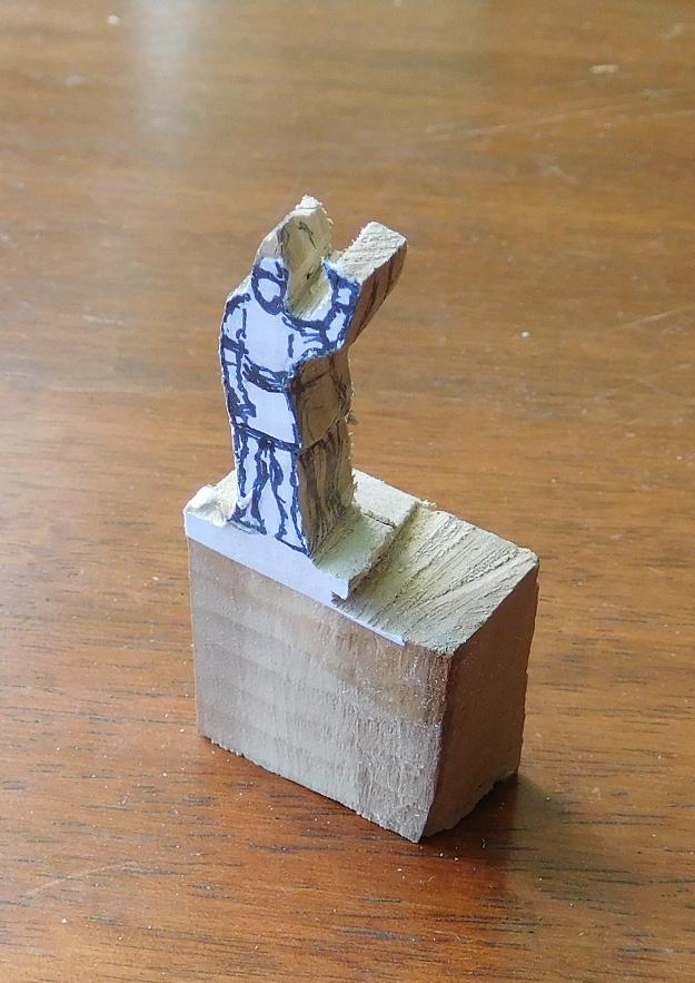
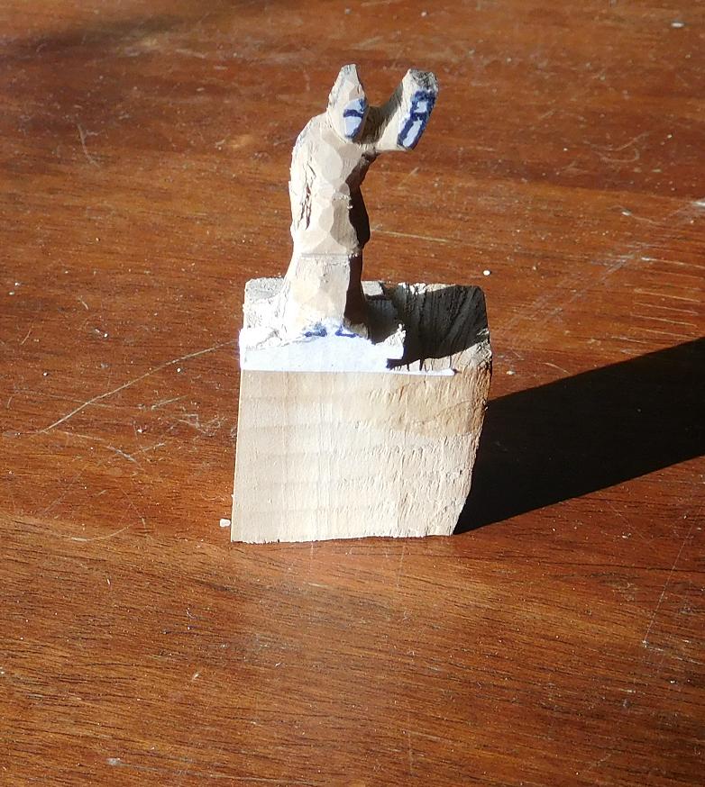
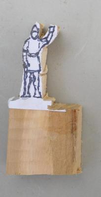
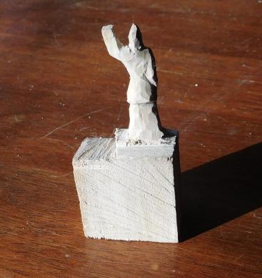
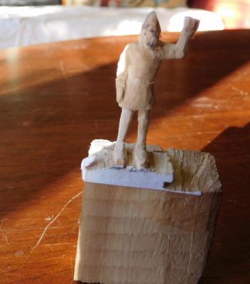
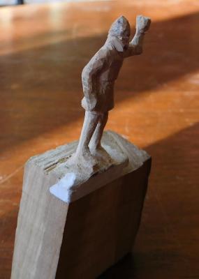
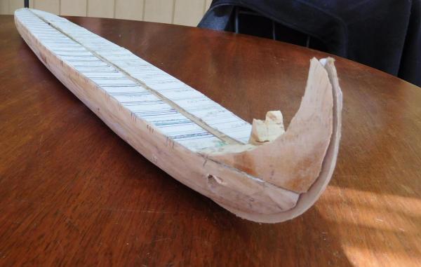
Latest progress. I've glued the plug together and slightly widened the gap between the sides so the stempost and sternpost can come out more easily when I remove them. I've added a bit of builder's filler to adjust the shape of the upper works at the stern so the sheer is a smoother curve at the tail, and drawn transverse lines for the frames either side of the oarports, so I don't have to cut a frame to put an oarport in. I should be able to get away with 21 frames at this stage - out of a total of 127. The rest will be added after the planking is finished. I've cut timber to 1/2 millimetre for the pine planks. I used a dropsaw - not perhaps the most elegant method, and there was a fair bit of wastage with planks that came out too thick, but I'm pretty happy with the result. And I've carved my first crewman out of pear wood. Not quite finished, but well on the way. Still needs a lot of smoothing off to get rid of the blade marks. I'm not totally happy with him - I might not end up using him, as his face leaves a bit to be desired. He's intended to be standing on the deck holding onto a shroud. The hand isn't finished yet, and might not be till I'm able to put him in position on the deck. Still, rather fun after carving a bunch of oars all the same. Ten done now - only 90 to go!


-
Dick, I'd suggest you go for it - write your article and send it to Mariner's Mirror. I've found that even academics are more interested in the addition to the fund of knowledge than in the letters after a person's name. I've been thinking of writing one on my dromon when it's finished. You might have to get a bit of coaching in how to present the paper, and how to add references, bibliography etc., but you can pick a lot of that up by reading academic papers, like some of the TAMU ones you've already looked at. You've made some very worthwhile and valuable discoveries during your build and lack of academic qualifications is no reason not to share the results of your research. I believe it would stir up a lot of interest. You might like to contact Glenn, who's currently building a paddle wheeler on this forum. He's at TAMU and might be able to help out. Steven
-
Ben, if you want a stable, flat-bottomed ship that nonetheless resembles a Viking ship as you mentioned earlier, you might like to look at the rather graceful Mediterranean ship which sank about 1025 at serce limani off the coast of what is now Turkey - you can see a 3D image here and its lines here
-
Lovely work, Dick. You continue to amaze with the quality and beauty of this build. Steven
-
Thanks, Carl. Yes, there are videos of working biremes both on youtube and here on MSW. Way out of my league, I'm afraid. I'll stick with what I know and stay with a static model - radio control is a whole other subject that I have no idea about, though my hat goes off to those who master it. Steven
-
Nice pictures, Tadeusz. These really are lovely-looking ships. Steve, just a point of interest - the rigging on these ships is mainly based upon educated guesswork. No cordage has survived, as far as I'm aware, on any Viking ship found so far (though they have found various things which appear to work as deadeyes and other artefacts which seem to belong with the rigging, and there are also a few rather interesting representations of rigging - though far too vague to be terribly helpful - on Viking runestones). However, these replicas have sailed long distances under all sorts of conditions and have had time to work out any bugs in the rigging. It may not be exactly as the Vikings used, but it certainly works as it is, and we'll probably never know any better. Steven
-
Amazing work. Makes my poor efforts look very ham-fisted. Still, the only way to get better is to practise, practise, practise . . . Steven
- 641 replies
-
- 6
-
-
- greenwich hospital
- barge
- (and 1 more)
-
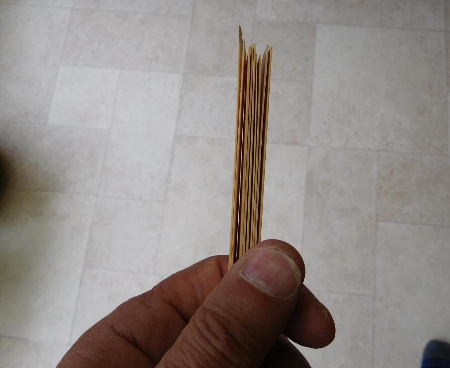
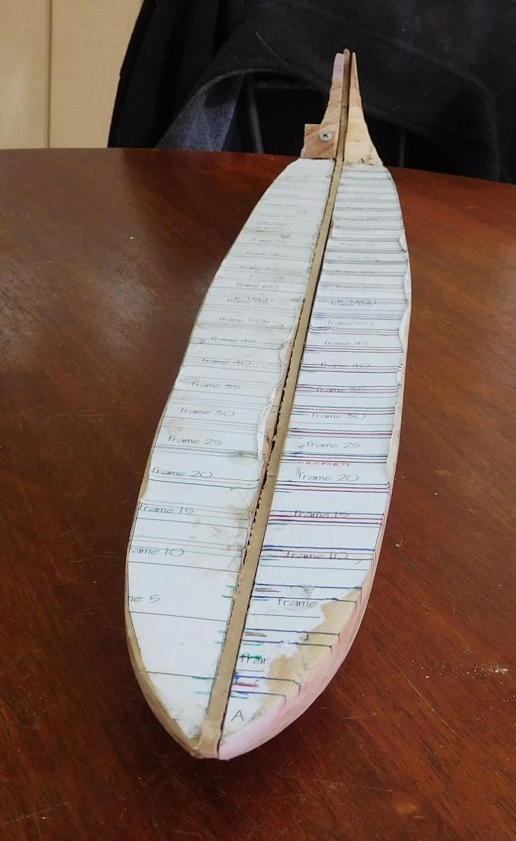
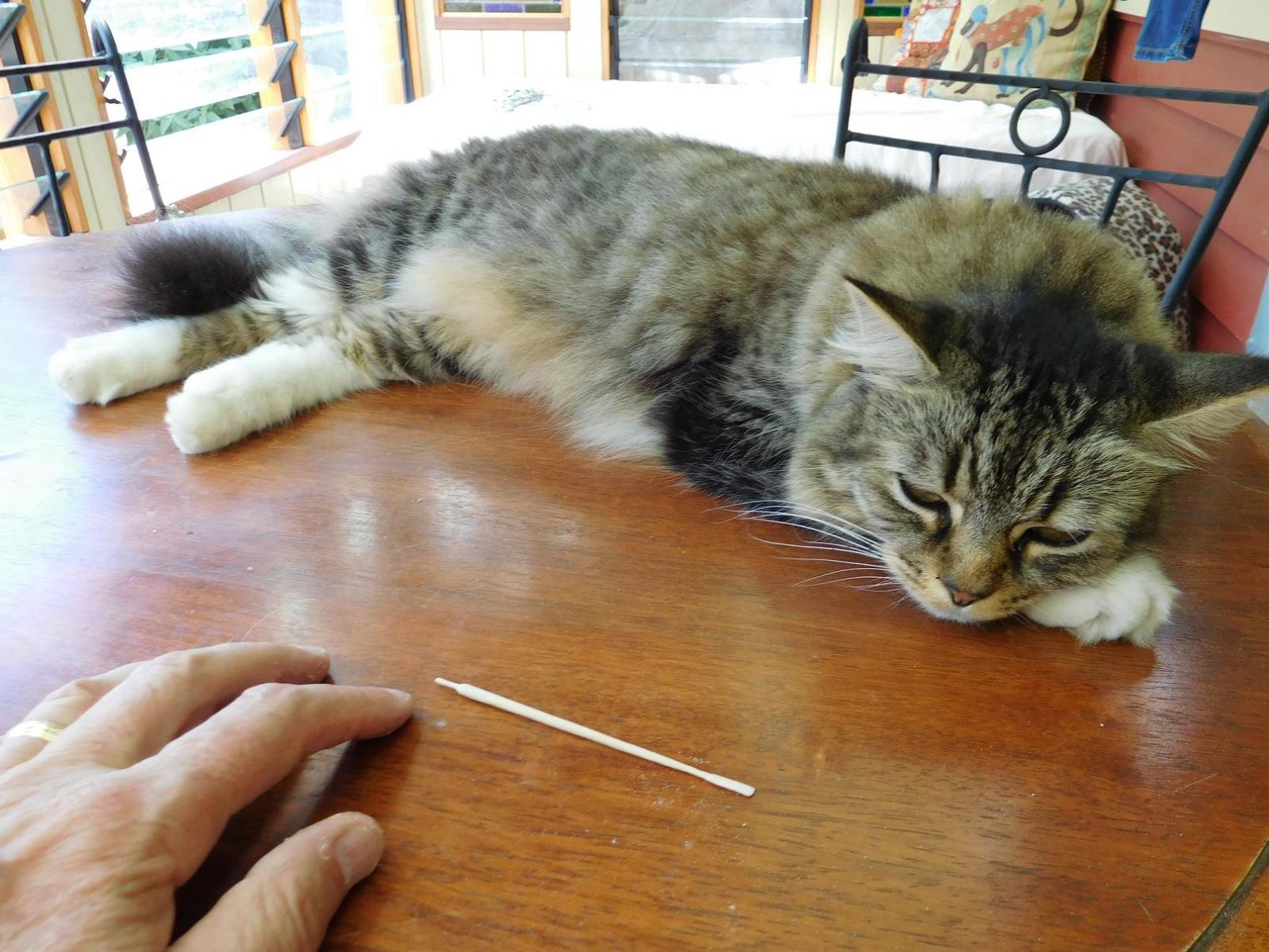
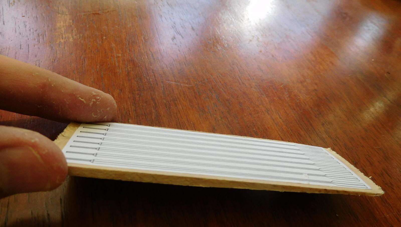
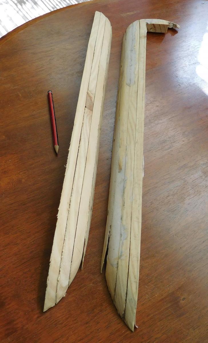
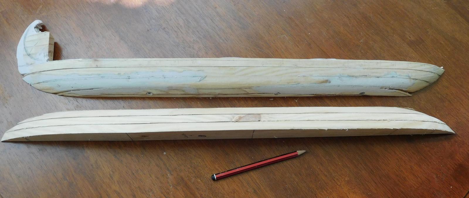
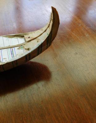
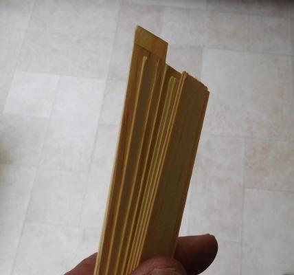
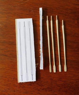
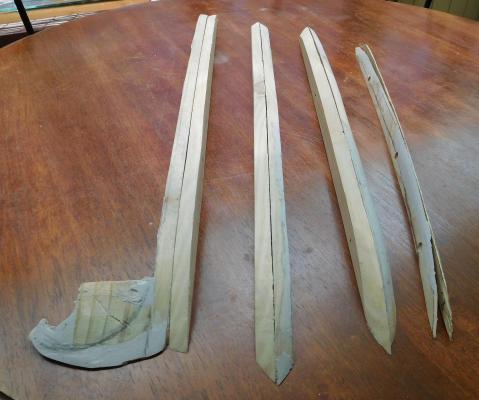
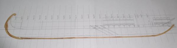
More progress on the plug. I’ve sanded down all the builder’s filler from yesterday and got it pretty much where I want it. However, somehow the curve of the tail doesn’t seem to quite line up with my original drawings. As I’ve made the sternpost and the ‘tailpiece’ to go with the drawings, there may be some conflict. I have two options if it doesn’t all line up: I can use more builder’s filler to build the stern up and then sand it to shape so it fits the pieces I’ve already made, or I can make new ones to fit the current shape. But I’m going to finalise the central spine with cut-outs for the stem and stern-posts before I commit myself to doing either, so I know where I am. I’ve currently just screwed the two halves of the plug together with the central spine between, to see how it all works together.There’s still some adjustment to be done – the two halves don’t fit quite tightly together along the whole length, so I’ll probably have to do a bit more sanding, or else I can clamp it all together and glue it as-is. I think I prefer to take a bit more time and get it right. And for some idea of scale, here’s one of our cats (and my hand) with an oar plus one of a sheet of wood with oar templates glued on, which I’ve tapered down in thickness to save doing them individually, (as per my previous post) and another of me holding it to show the taper.


-
Thanks everybody for all the 'likes'. Cog, thanks for the interest. I won't be doing the lower oars differently - they'll be made the same way and they'll look the same. But the part of the oar that's inside the ship won't need to have the small handle at the end, because you won't be able to see it. And I can take advantage of that to make a different end to the oars, to fit in a bracket or rack which will hold all the lower oars in place. I should do a diagram to show what I mean - except I'm not yet totally clear in my mind how I'm going to do it. It's easier to make the blades as part of the oars - they're so small that adding the blades separately would be much more difficult than just carving them out of one piece. Druxey, thanks for the encouragement. I really prefer to be making the oars individually by hand and keeping casting to a minimum. It's a personal pride thing, and anyway, it's a wooden model after all, and I think I should make everything from wood that I can . To answer your question, the longer ones are about 5.4 metres long full size - that's a little under 18 feet. The shorter ones are about 4.5 metres if I remember correctly. The looms are maybe 125mm (5") thick at the larger end. Gerhard, I had a small modelmaker's lathe when I was a teenager, and it would probably have been ideal for the job. But when I moved out of home I couldn't take it with me and it must have got thrown out years ago. I'm not sure my lathe skills are good enough, but I was just asking yesterday about the cost of small lathes, and they're well outside my budget at the moment. It would be nice to be able to get the oars more consistently the same, but I'm pretty happy with the way they're turning out. Maybe one day I'll get a lathe and try again. But probably not. Once I've made the dromon, there are a whole lot of other ship types I want to try making. Steven
-
Thanks for the suggestion, Mark. I expect I'll be casting the oarsmen (too much carving, even for me!). But I love working with the wood to make the oars and I get a great sense of accomplishment from making them. The (very) minor differences between the oars actually look much greater in the photo than they do to the naked eye - one of the problems with high-definition photos, I suppose. Steven
-
Lovely work, Druxey. It's proceeding very well and looking magnificent. Steven
- 641 replies
-
- 3
-
-
- greenwich hospital
- barge
- (and 1 more)
-
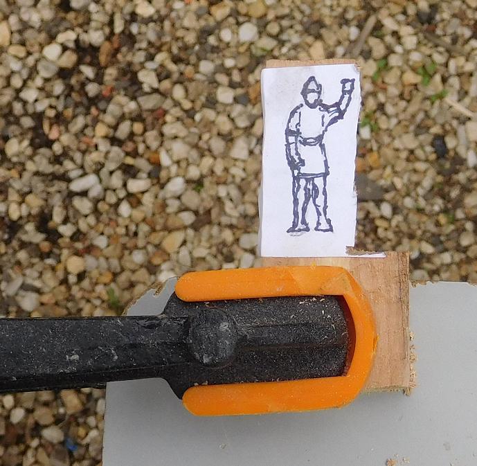
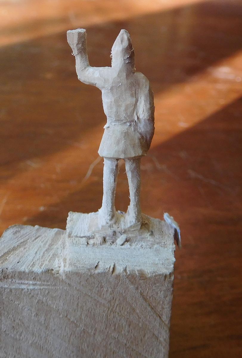
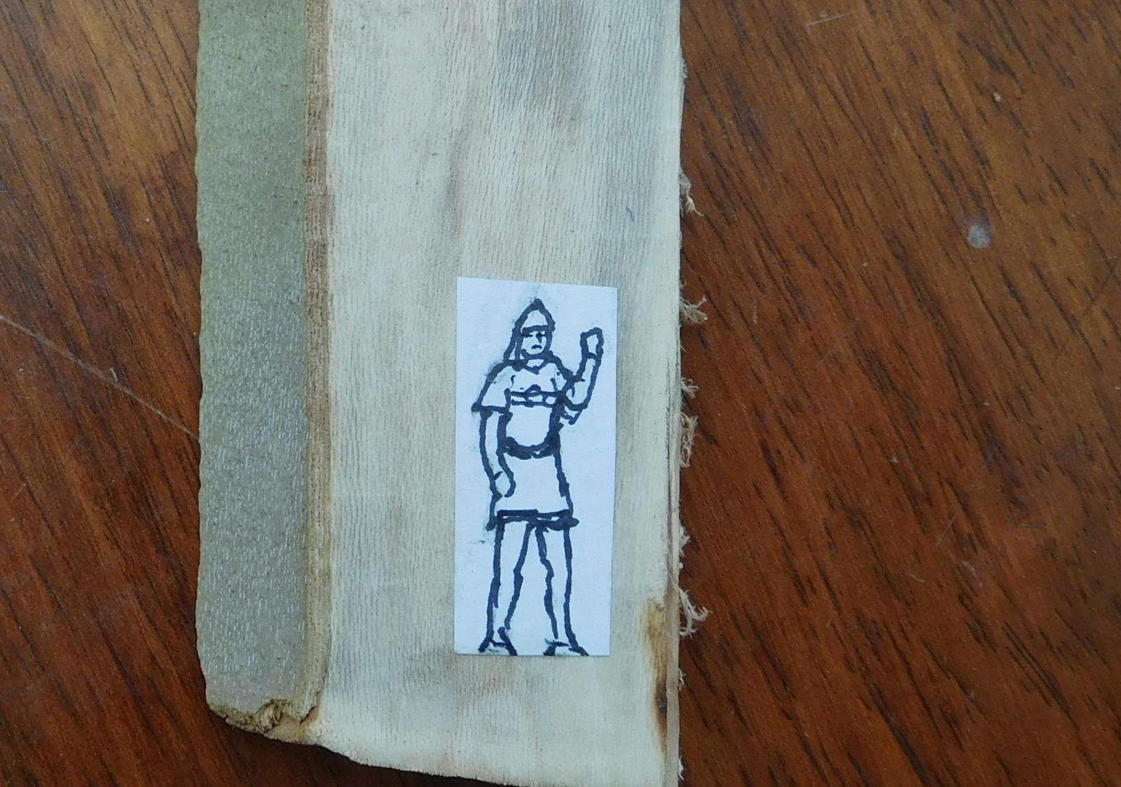
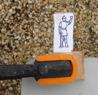
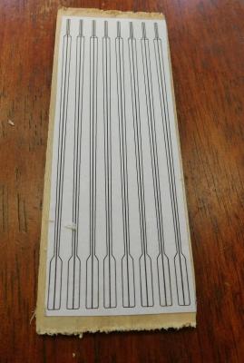
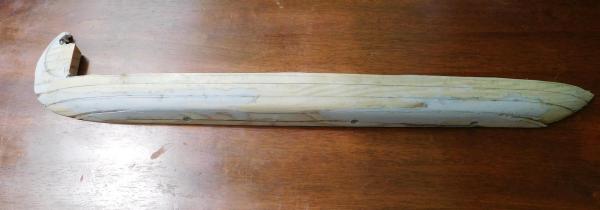
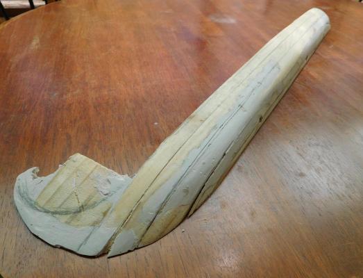
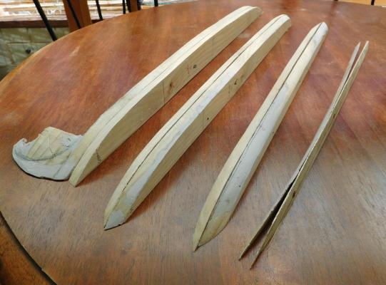
For one reason and another, | didn’t get a chance to shape the plug for the dromon last weekend, so I’ve got into it again this weekend. Still a work in progress – it’s not bad, but I took a little too much wood away on the second side (just as I did on the first) so I’ve used builder’s filler to build it up again, and I have to wait till tomorrow for it to dry so I can do the final sanding, to get exactly the cross-sections I want. I’ll put up pictures when it’s done. In the meantime, each evening when I get home from work I’ve been making oars. The dromon will have 100 oars in all – 25 per side in both upper and lower banks. I’ve worked out that if I make one oar each evening I’ll have them all done in four months. So far I’ve made 4 upper bank oars and one lower one – only 95 to go! (the photo only shows four, but that was taken this morning - I’ve made another oar since then).As the photo shows, it's very difficult to get all the oars exactly the same. But as they're only 2.5mm (1/10') in diameter at their thickest, I don't think I've done too bad a job. After I discovered how much work is involved in individually marking out each oar before cutting out, I decided to use AutoCad to print them off in bulk onto a sheet of paper so I could cut out and glue groups of oars onto the wood and then saw them out roughly to shape. After that I’ve been using a Stanley knife to trim down each oar, taper the thickness and round it off, smoothing off with files of progressively finer levels of ‘cut’. Today I began to use the power sander to taper the thickness, which cuts out a fair bit of work with the Stanley knife. And now I’ve realised I can short-cut it further if all the oars face the same way, because I can use the sander to roughly taper the thickness of a sheet of wood with a whole lot of them on it before I cut them out, so all the oars are done at the same time. So I’ll change the AutoCad drawing and print off again. The upper oars are somewhat longer than the lower ones, and because the upper oarsmen are above decks, the oars will be visible in their entirety, so they need to be properly shaped all the way along their length. The lower oarsmen are below decks, so the part of the oars that is inboard won’t be visible. So this means that from the fulcrum inboard they don’t have to be ‘oar-shaped’. I’ll probably make some kind of rack to support their inboard ends so they don’t flop around, and shape the ends to slot into the rack. This is something of a bonus, because getting oar handles right is possibly the hardest part of the job. I’ve already made one lower bank oar with a ‘proper’ handle, but I won’t be making more until I’ve decided exactly what to do – I’ll stick to upper oars for the time being. I've drawn and pasted to a piece of wood the first crew member who I'll carve out to pass the time when I get bored with making oars or shaping the hull. He's a stradiote - a marine. He'll be in Byzantine style armour, complete with helmet and sword. In fact all the upper oarsmen served as marines as well, and took the major part in any combat that occurred. It was left to the lower oarsmen to keep the vessel moving when she went into battle.

-
I'm really enjoying watching the progress of this wonderful build. I particularly like the precision and attention to detail, particularly with something so small, but also watching the problem-solving is a real education. Steven
- 641 replies
-
- 2
-
-
- greenwich hospital
- barge
- (and 1 more)
-
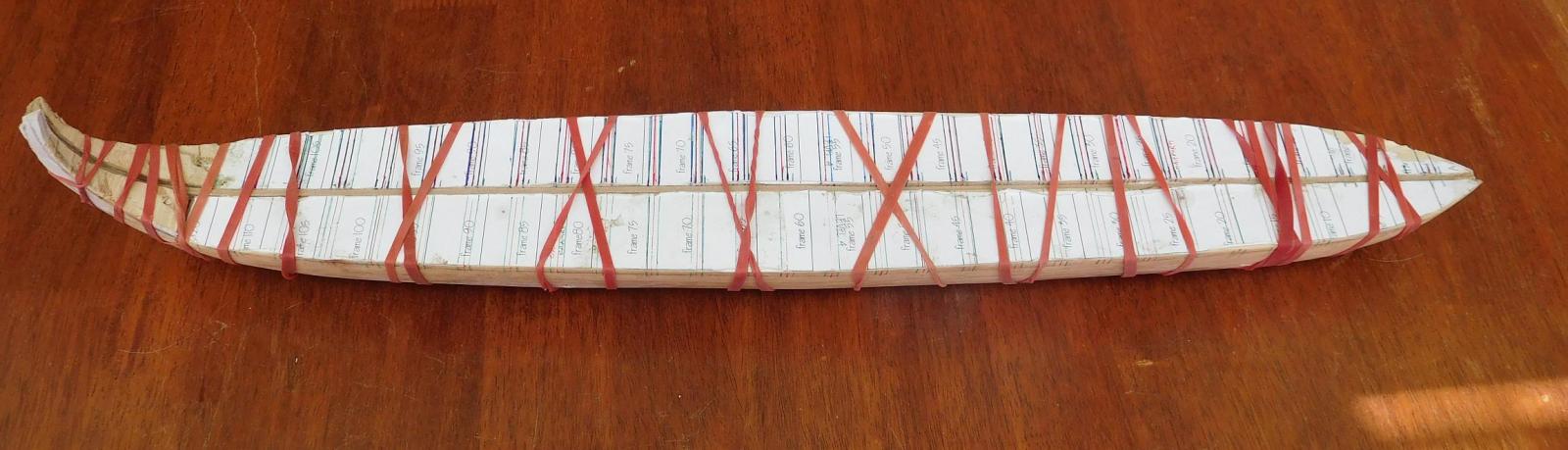
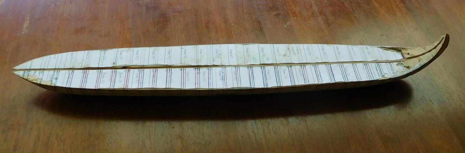
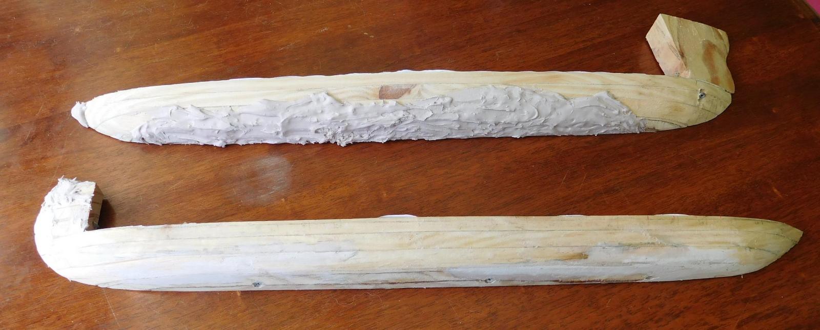
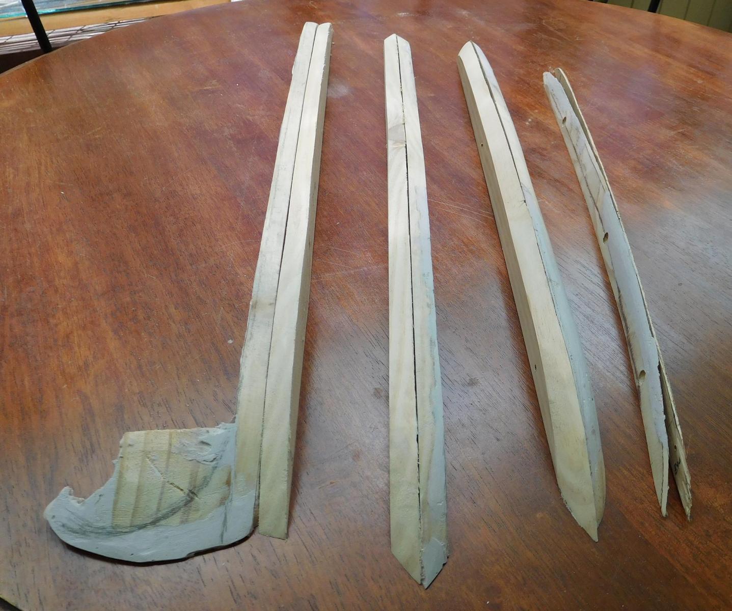
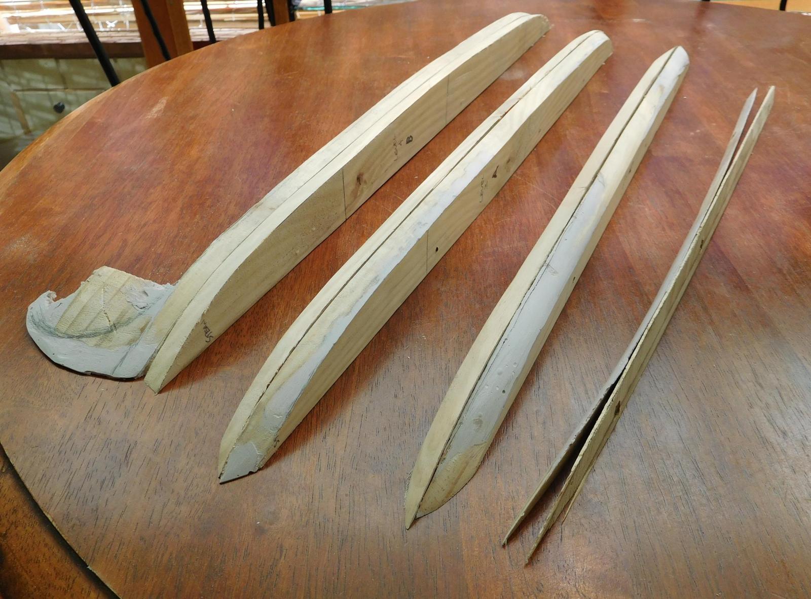
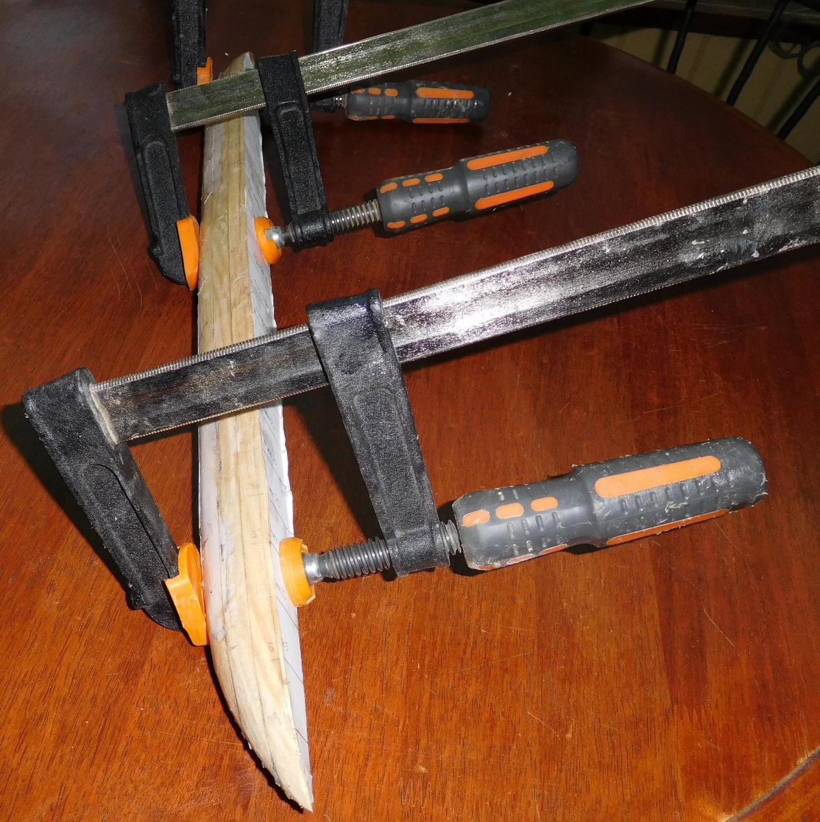
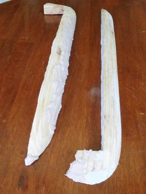
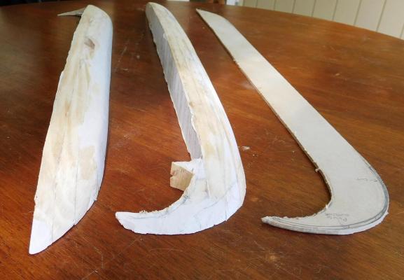
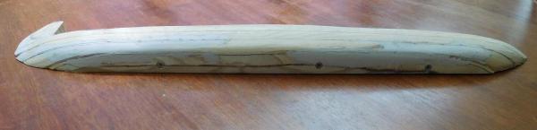
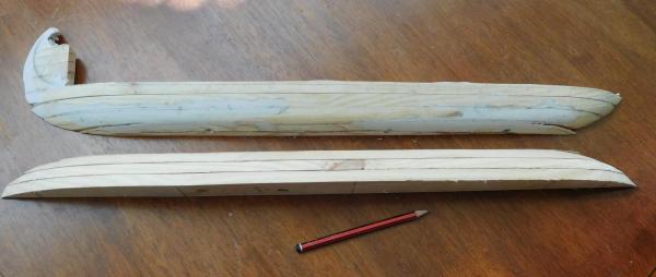
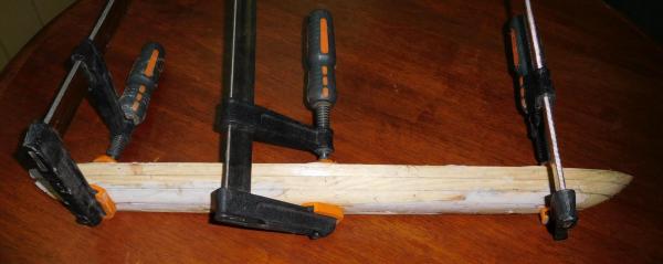
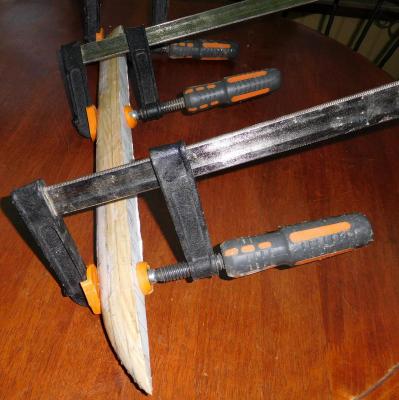
I’ve spent quite a bit of time on the weekend on the plug and it’s almost complete. My idea was to screw the lifts of one half-hull together and shape the half-hull, then take it apart again. Then I’d form up each lift of the second side by putting it back-to-back with its opposite number to make sure the second half mirrored the first. The lifts are 12mm (1/2”) thick pine plank, except for the one at the bottom, which is made of 6mm thick ply. The hull’s cross-section changes shape dramatically about 6mm above the keel, and I decided that this would be the best way to control the change of section. I used a belt sander to take off the excess wood and all went well until I had the first half-hull shaped. I’d cut out a bunch of concave templates of the cross-sections at 1 centimetre intervals to put against the hull to check the shape at each point. It wasn’t too far off, but I discovered I’d sanded a little too much off in places, so I covered the relevant areas with a bit of builder’s filler, waited for it to dry and carefully sanded it until it was the exact shape at each cross-section. Then I hand-sanded the surface (actually I used a file – it seems to work just as well as sandpaper) until it was nice and smooth. Unfortunately, once I’d done that I realised that I’d painted myself into a corner. With the builder’s filler over the joins between the lifts, I couldn’t separate them by simply undoing the screws. So I had to cut through the filler at the joins with a Stanley knife (box cutter), which rather spoiled my nice smooth finish. Anyhow, I’ve now belt-sanded the lifts of the second half roughly to shape using the lifts of the other side as models.There’s a little more shaping to be done where the lifts meet each other, but it’s looking pretty good. However, because the lifts aren’t yet glued together, the bottom lift has started to bend at the ends. It's only made out of 6mm three ply and is sanded right down to nothing at one edge, so it’s a very long thin triangle. I’m not concerned by this, as gluing and tightly clamping all the lifts together will fix it quite easily. I’ve screwed the second side together and it looks ok. Today (Monday) I glued the lifts of one side together, and tomorrow when that’s dry (and the clamps are free again) I’ll do the other side. I’ve also discovered why I couldn’t get the tail to follow the curve I wanted. The sternpost turned out to be not a tight enough curve, so no matter what I did it wouldn’t do what I wanted. It was only a smidgin out – I only had to bring the ends in about half a millimetre (about 1/50 inch) and push the middle of the curve out by about the same amount. I’ve made a new one with a slightly tighter curve and I’ve started refining its shape and working on the first scarph joint, where it joins the keel. Now I’ve fixed that, I’ve found that the ‘tailpiece’ which joins to the sternpost is the right shape to follow the curve, so I don’t need to make a new one. Next weekend I’ll be doing more on the plug and the sternpost. I still need to make the part of the second half that corresponds to the tail and smooth it off. Then I’ll have to cut grooves in the plug for the frames. I’ve marked the positions of the lower oarports to make sure the frames don’t cross them, so I’ll be measuring very carefully to get them in the right places. Once that’s all done I’ll be ready to start making the frames – they’re going to be only 1mm (1/25") square in section, so I’ll have my work cut out for me, particularly as I don’t have a bench saw. However, I’m good mates with the bloke across the road who does have one, and he should be willing to cut my planetree wood into 1mm slices for me. Steven

-
That's a really good discovery, Dick. Adds that extra special something and, I think, adds to the meaning of the model to know who it belonged to. By the way, I notice there are two small copies of the coat of arms at the bottom of his portrait, as well.
-
Thanks for the information, Glenn. Yes that seems pretty clear. I'll have another look at the paper later and see if I can locate those timbers.They really put a lot of thought into these vessels, didn't they? Give my thanks and regards to Cemal. The trouble is that at this stage of the build I'm pretty much committed to the design I have, so I'll be going with a straight keel (though with a very slight downward bow I haven't been able to get rid of). However, what I'm calling the stem and sternposts are curved upward, so maybe I'm closer to the actual design than I thought. Druxey, I'm quite surprised that just squeezing with the fingers is enough. Do you mean you hold it in your fingers till the glue is dry, or do you just push the pieces together and that's enough? I think I might have to hold mine together somehow, as I'm not all that confident in my scarph joints or the straightness of my pieces, especially the troublesome keel. I don't think they'll just lie there together on a flat surface without rolling a little out of position. I don't think it's enough to spoil the model, but after all that work and getting it almost straight I just don't know that trying it again and making another one would produce any better result. I spent the weekend on the plug and I'm pretty happy with it. I'll put photos up in the next day or two. Steven