Louie da fly
-
Posts
7,993 -
Joined
-
Last visited
Content Type
Profiles
Forums
Gallery
Events
Everything posted by Louie da fly
-
 I realise it's too late for your build, Ian, but I figure this might be worthwhile for everybody interested in Viking ships. I thought I'd seen a photo years ago of a stempost from a Viking ship, and lo and behold! I was right. Here it is. Steven
 -
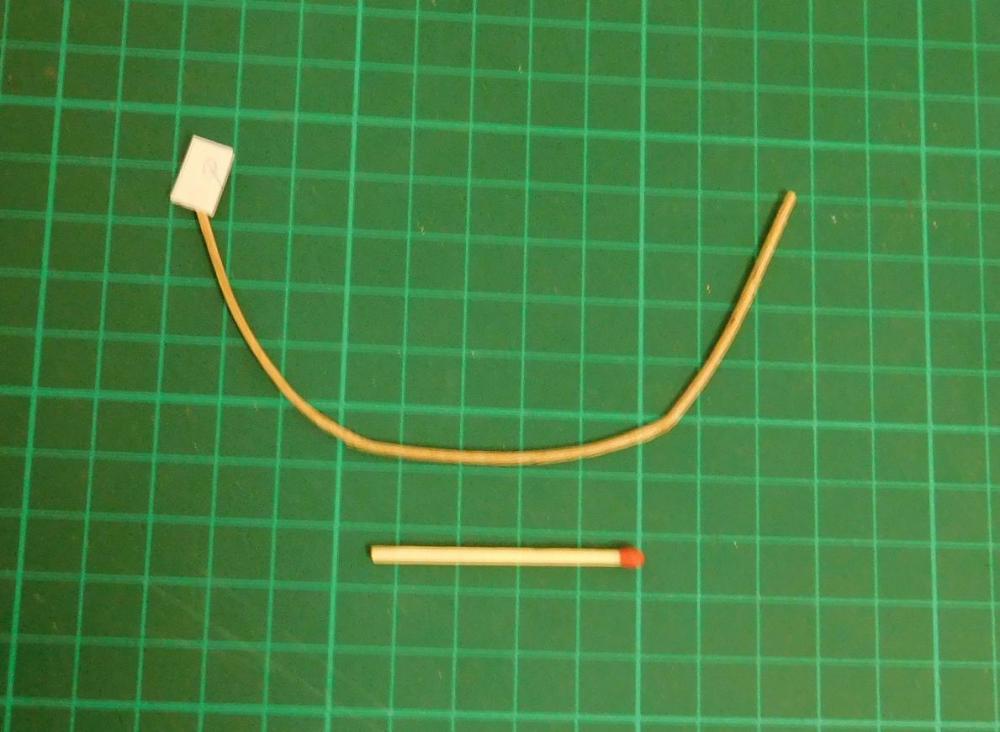
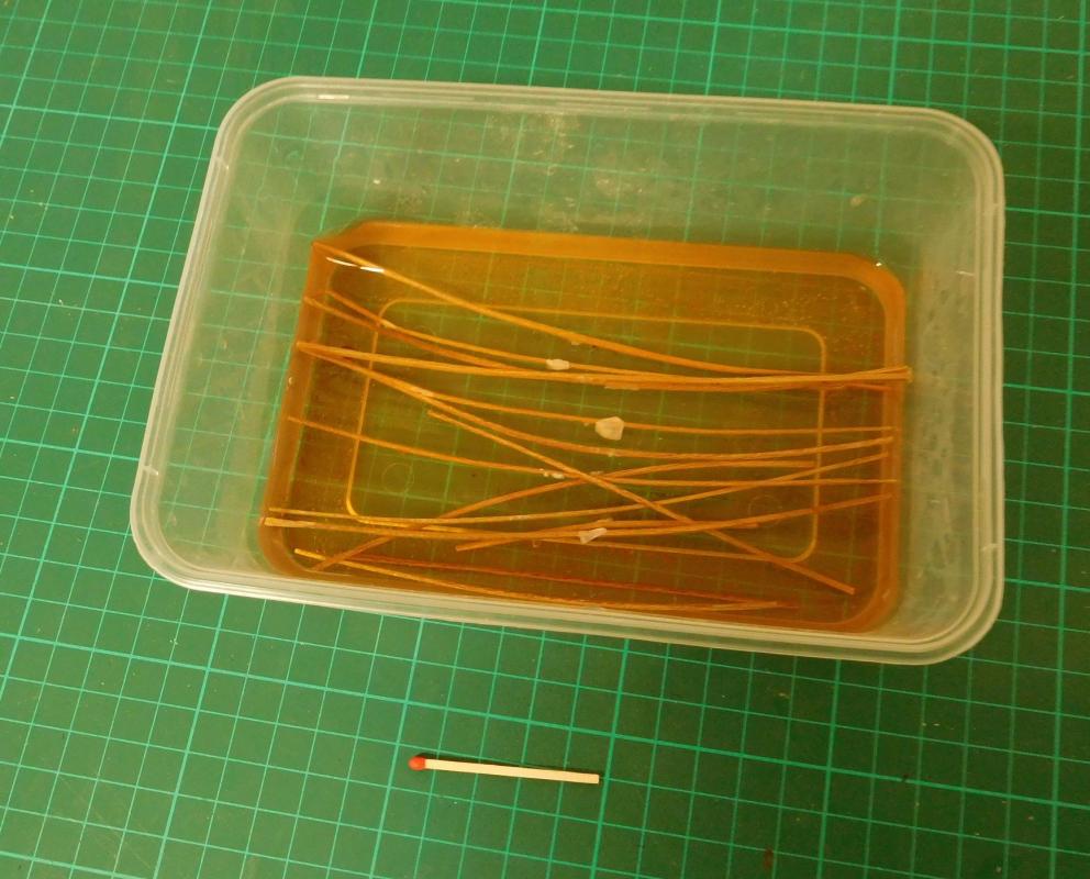
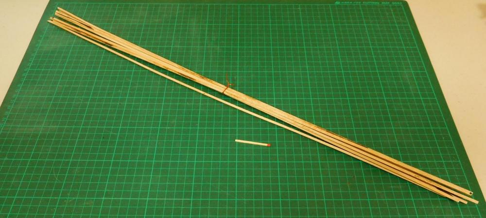
After a delay due to various unavoidable factors I’ve finally completed the last set of frames and bent them to shape on the plug. Unfortunately, now I’m not happy with some of the first ones I did – they’re not quite the right shape and I’ve got them soaking so I can re-bend them. Though I've replaced the water, it's gone a rather dark brown due to residue in the container from the tannin in all the wood I've been soaking. As I mentioned before, over half the last batch of frames snapped in two as I tried to bend them and I had to start over. Since then I’ve noticed three on the plug that hadn’t snapped completely in two but had partially broken at the bend. Following the technique of another modeller on this forum (forgotten who it was, but thank you!) I managed to plug up the break with a mix of PVA glue and sawdust (fortunately I had a LOT of sawdust from filing the frames down to shape). The frames were still in the plug when I did this and I was worried the glue would make them stick in the grooves and I’d have to chisel them out, wasting them. But all went well, and I’m happy to have retrieved 3 frames that would otherwise have been thrown away. Here’s a photo of one, as good as new. I’ve put to one side the strips that I’d trimmed down to make into frames but broke or were made out of ‘snappy’ wood. I might be able to use them when I build the light wooden superstructure. The man across the road with the bench saw kindly cut all my wales for me from 3mm planetree timber he’d earlier cut from some tree loppings I picked up on the side of the road. So now I have about 16 wales 3mmx3mm (1/8” square) which I now have to bend to shape. Now I have to make a steamer for myself to bend the wales. I’ve been looking up how to steam and bend timber. The steam box seems very simple, but I have to scout around for a source of steam. The most likely is an old tea urn, if I can lay my hands on one. Fortunately I’m only going to need 10 wales, so I have 6 to experiment on and waste if things don’t go well as I’m learning how to do it. The admiral has very kindly given me an old white pillow case which has reached the end of its usable life – as a pillow case. The fabric is very thin now, and is ideal for sails, so I’ve got enough fabric to equip a dromon flotilla! Steven
-
It's very true. Galleys (full size) had very low freeboard and couldn't cope with waves or swell more than about a metre/yard. History is full of sccoumts of entire fleets of galleys being sunk by unexpected Mediterranean storms. Yet galleys dominated the Mefiterranean for maybe 2000 years. Steven
-
Dick I take on board your comments and to be frank I think I haven't previously given enough thought to this issue. Druxey, your advice seems to be the way to go. With such frail frames and planks, I think that unless I make very sure the wales are pre-formed exactly to shape they're likely to deform the rest of the hull, so I'll have to take vdry great care to get them right. Steven
-
It's a bit frustrating cutting and shaping all these frames, soaking them for days and then having half of them break the moment you try to bend them. But it looks as though I can tell the good wood from the bad. If it's light brown it's ok. If it's sort if greyish it's likely to break. So I have maybe another 15 new ones to make and shape and bend. Fortunately I have plenty of wood to work with. And anyway it'll all have to wait till I get home. Steven
-
Quite right, Dick. It's certainly an issue. The plug will act as the jig, and I'm hoping that the wales (there are five each side) will give the hull rigidity as I'm doing the planking. I think I'll have to put the wales on first (they're about 3mmx3mm) and then plank between them. I'm still trying to work out what will be the best sequence with frames, keel, keelson, wales and planks. At the moment, though, I'm back to square one with the frames. About half of them broke when I tried to bend them to shape. I think I chose the wrong wood. It's too coarse grained - I think the ones that broke are sapwood while the good ones are heartwood. I've got to make a bunch more frames and start again. But I'm off to Sydney tomorrow for a few days so there'll be another gap before the next instalment. Steven
-
That's a lovely piece of work, Dave. Steven
- 962 replies
-
- 7
-

-
- sovereign of the seas
- ship of the line
- (and 1 more)
-
Thanks everybody for all the 'likes'. Druxey - yes, I'm pretty happy with the finish on these. It would probably be nice to have all the equipment and do it faster, but I think after all that work I probably have more of a sense of achievement than I otherwise would have. Trouble is, most of each frame will be covered up by the deck anyway, so really I'm doing it because otherwise I'd always know I'd accepted second best. Thanks for the comment, Glenn. I appreciate the feedback, especially from people whose work I respect, like you and Druxey. Steven
-
Wonderful work Glenn. She's really starting to take shape. Your build log is a real inspiration. Steven
-
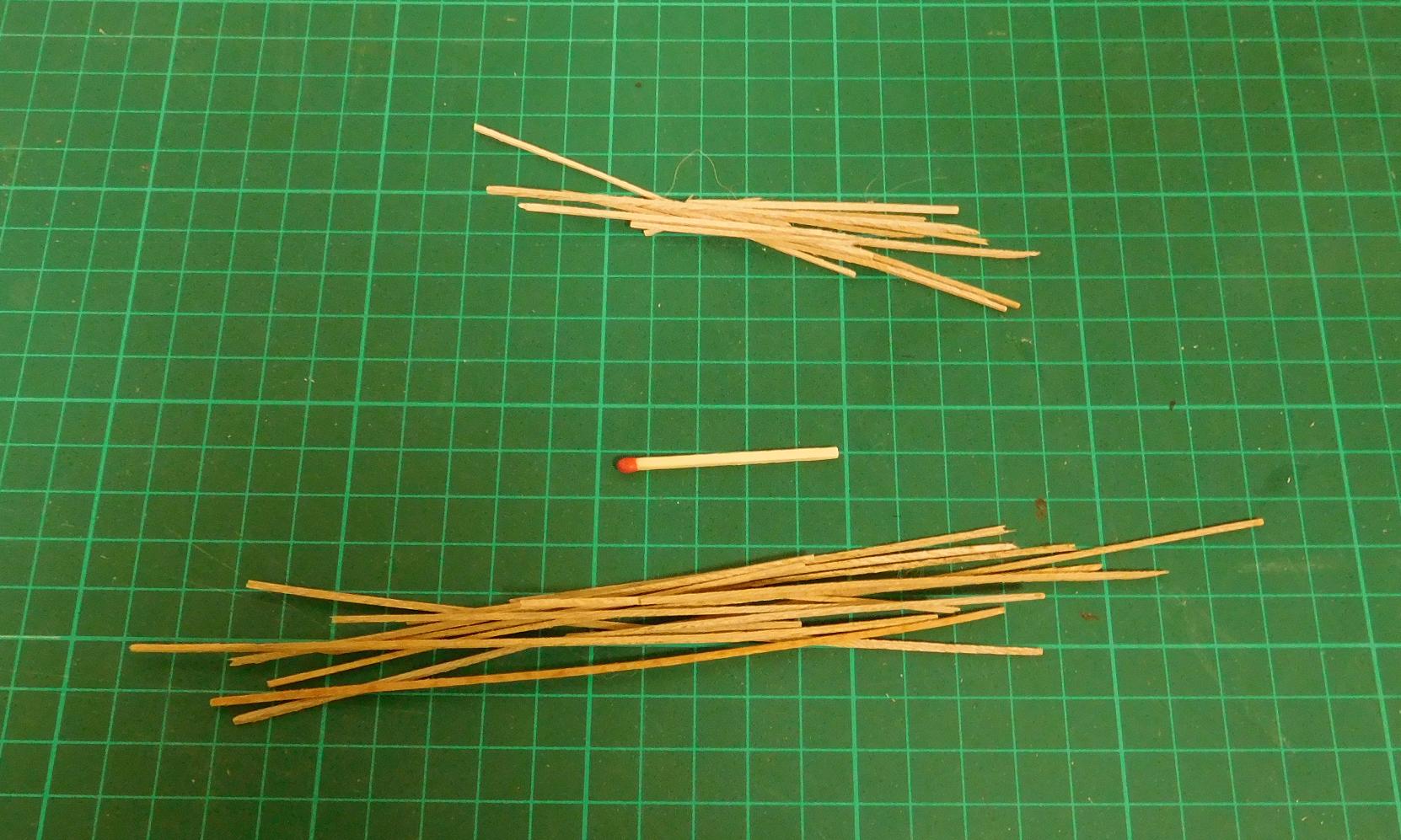
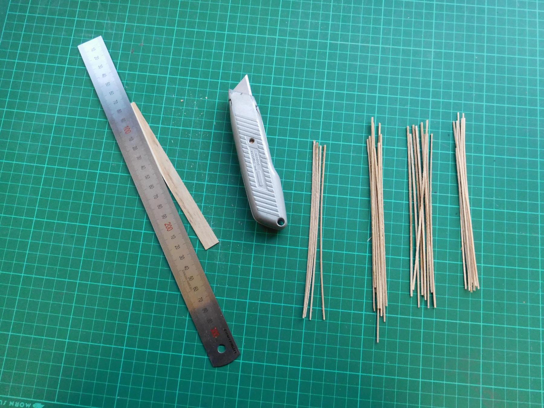
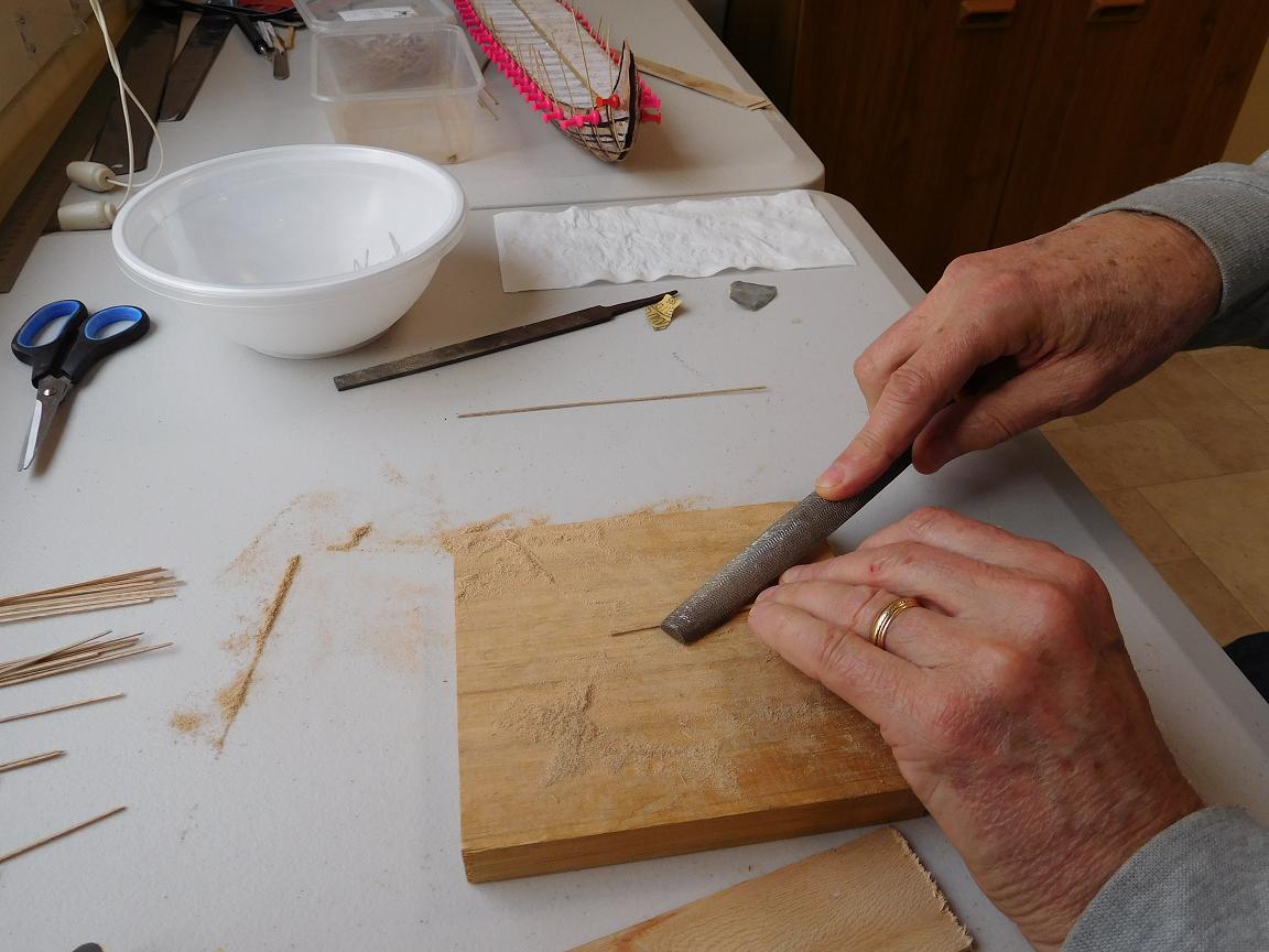
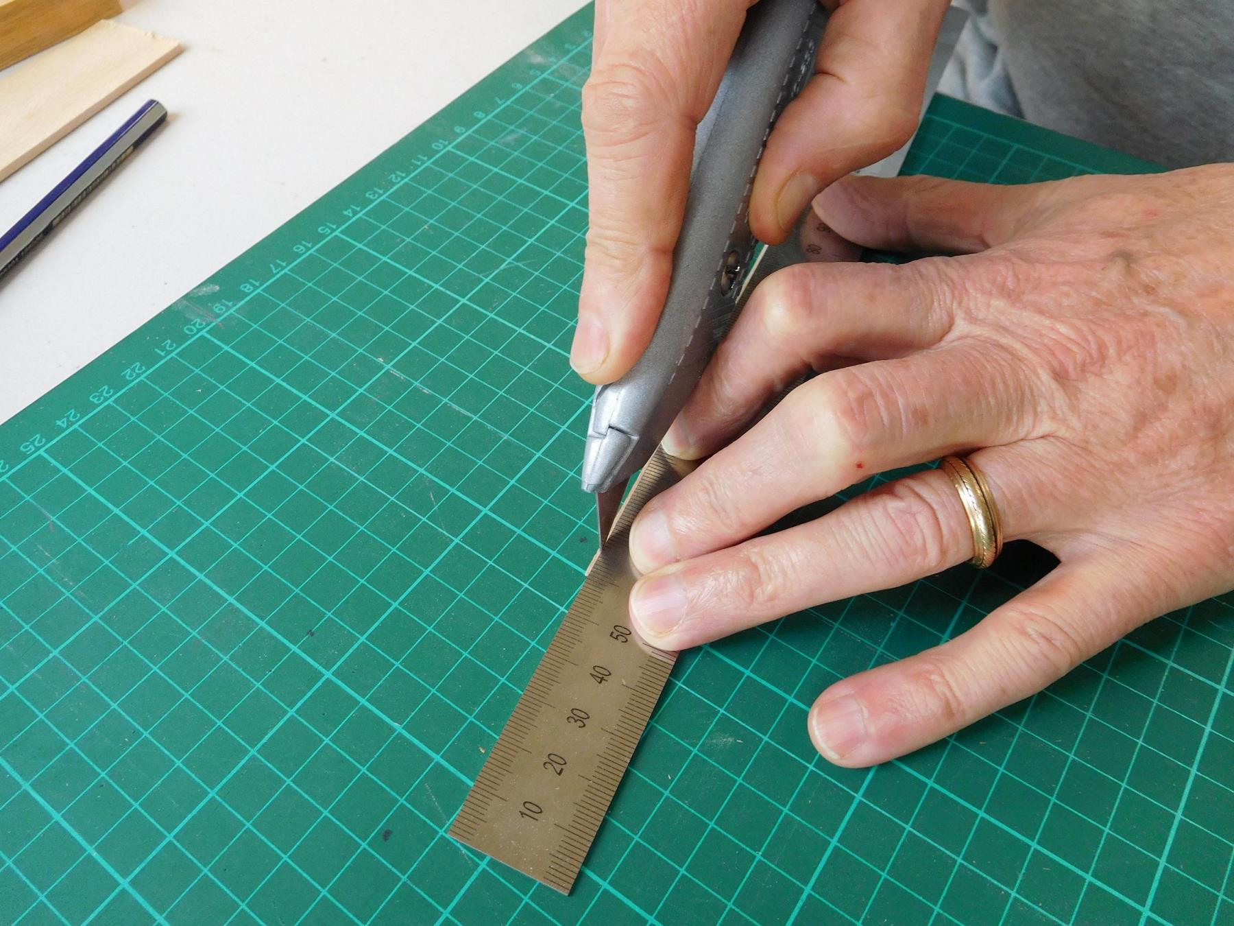
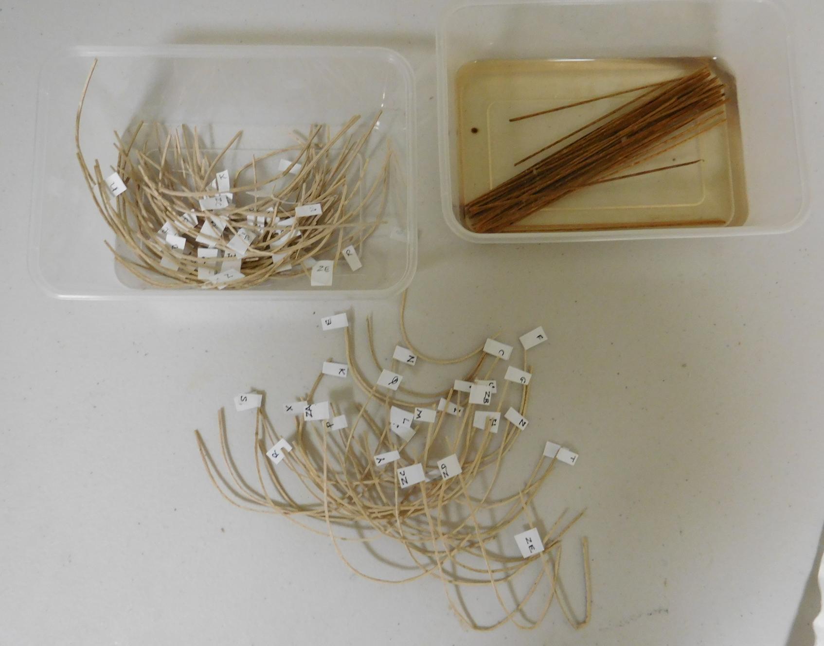
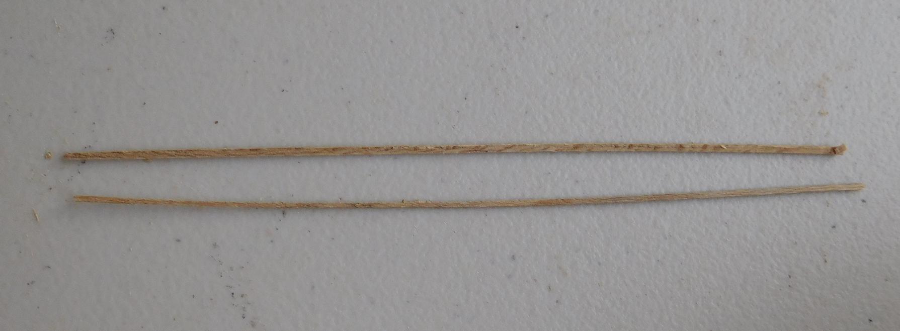
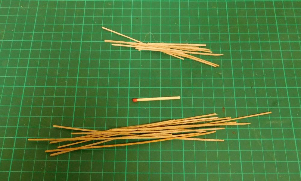
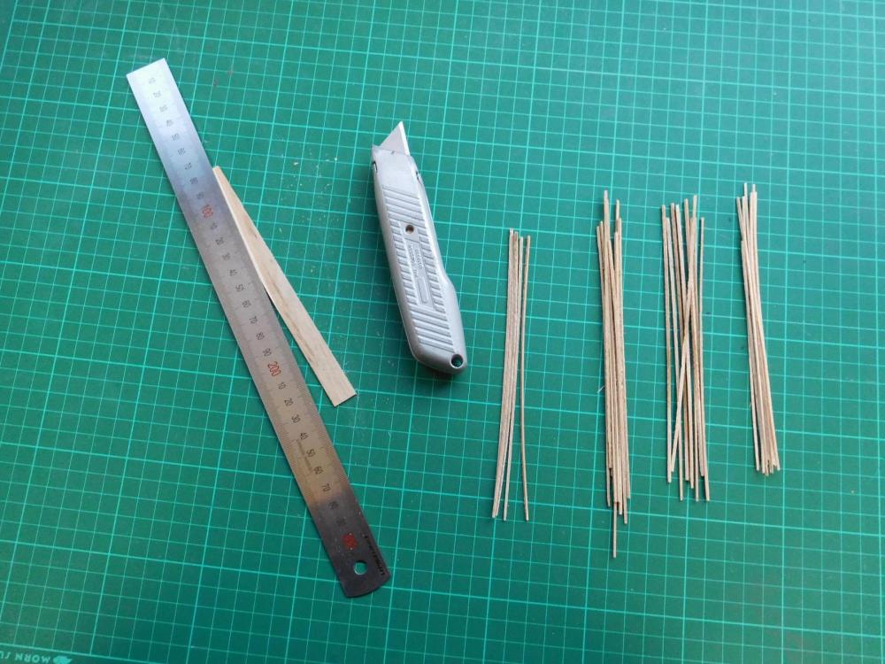
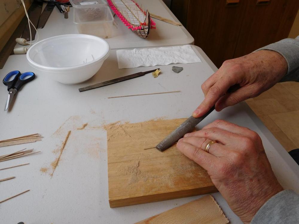
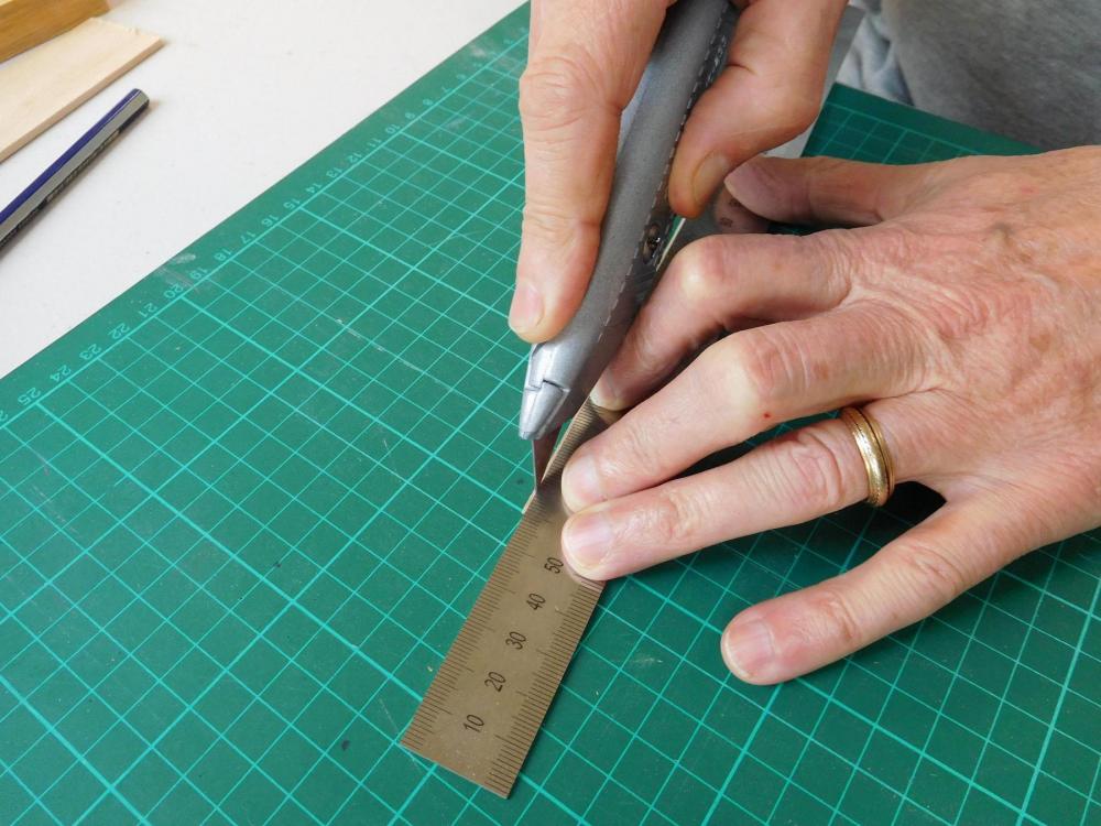
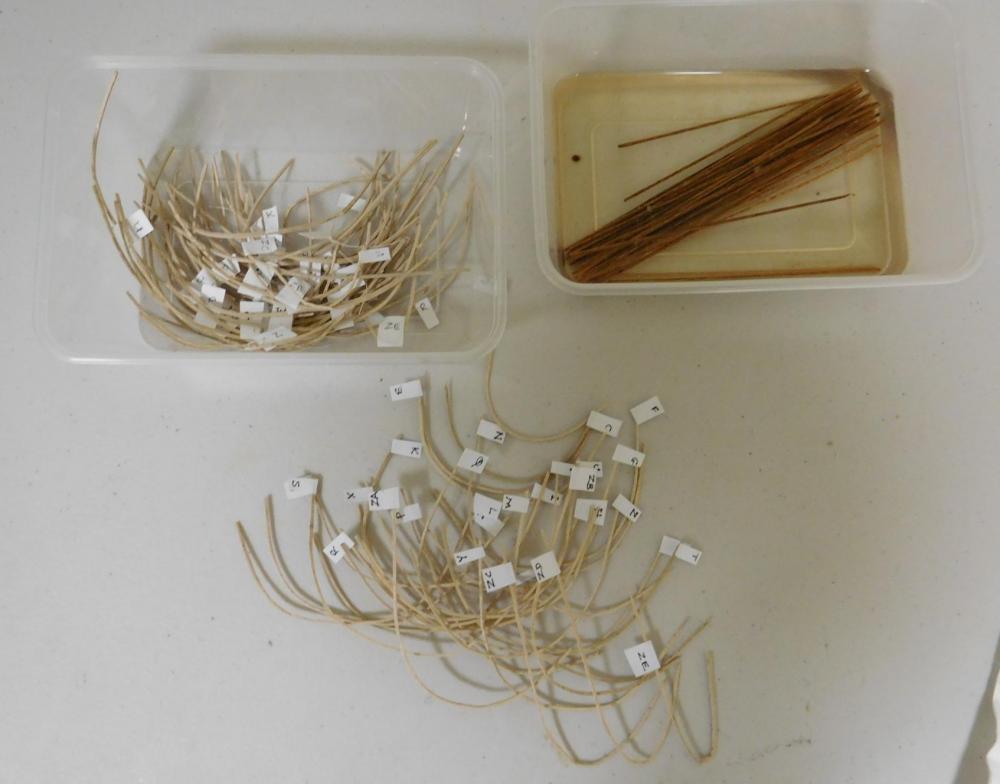
It's been a while since I posted last. I've been working on frames, but life's been getting in the way as well (I came down with the dreaded Lurgi and was not able to work for a while). I had already made 93 of the 124 frames needed. Here is a photographic record of making the last 31 frames, which are 1mm x 1mm (1/25 inch) in cross section. Cutting them accurately to such a small size is difficult, and I've found pretty much impossible in the real world. The sheet of wood I made them from was cut for me by the guy across the road with a bench saw not really suited to the job, so thickness varied from 1mm to 1.3mm. Then cutting a sliver 1mm wide with a Stanley knife is pretty hard to do without stuffing it up completely, so I erred on the conservative side figuring I can always take some wood off, but I can't put it back on. You might notice there are actually more than 31 frames in the pile. I made extras in case of breakages while bending them to shape, which happens every now and then. After I'd cut out the frames it was time to file them to size and shape, using a bastard (medium) file. Takes a while, and I had to quit at one point when I broke three frames one after the other. I came back after a bit of time off, and filed down the rest of them. After filing, I used wet and dry sandpaper to smooth off the corners, which were a bit rough after the filing. Here are two frames - one freshly cut and the other filed to size. Next job is to soak them in water for at least a day, preferably longer, so they'll bend properly without breaking. A take-away food container is ideal for the job. While they were soaking, I undid the previous 31 frames from the plug and labelled them with little slips of paper so I could tell them apart. So here are all the frames - 62 I'd already made, 31 just taken off the plug, and the last 31 (plus extras) soaking.

-
Beautiful work.
-
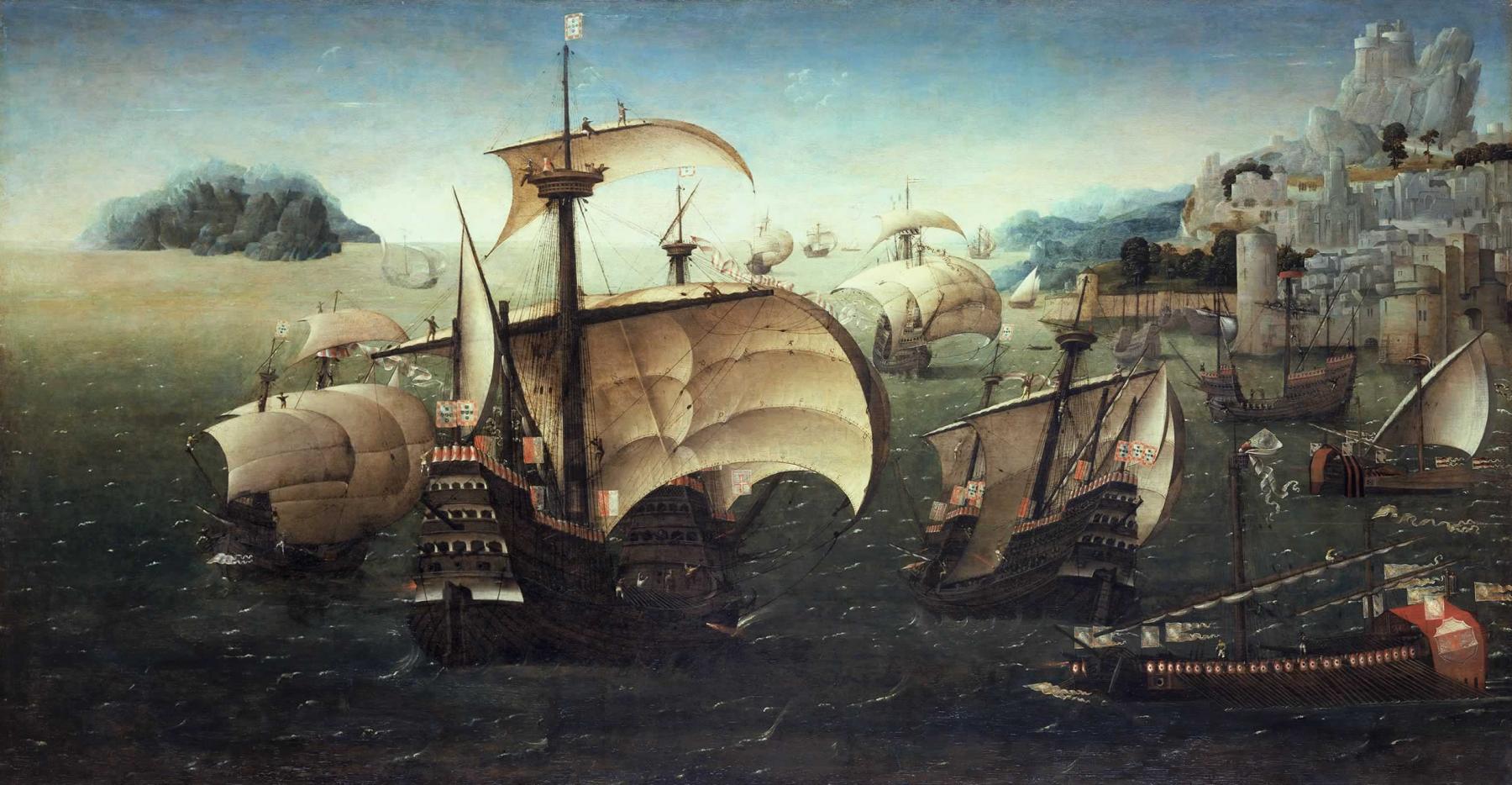
Actually it's Portuguese, but you're quite right. As Woodrat has demonstrated, there could be vast differences between the ships of various regions, and the Atlantic ships (including Spanish, Portuguese and Basque) were markedly different in shape and construction from the Mediterranean ones such as the Venetian one of this build log. As far as sail plans and rigging go, the differences seem to be equally marked. By the way, I've realised that the Santa Caterina's mainsail is actually made up of a course that only extends down from the yard a relatively small distance, plus two bonnets, each as wide as the course itself. A sensible thing in the days before reef-points. You could get rid of a lot of canvas relatively easily when it came on to blow. And with a mainsail that big, the forces involved could be quite dramatic in a strong wind. Steven
-
This picture of the Santa Caterina do Monto Sinai, though a little late, shows two sheets holding the centre of the mainsail back, plus two others starboard of it (presumably mirrored on the port side), and the sail pressed hardup against the forestay. Steven

-
I'll be following this build with interest. Carracks are a great love of mine. Steven
-
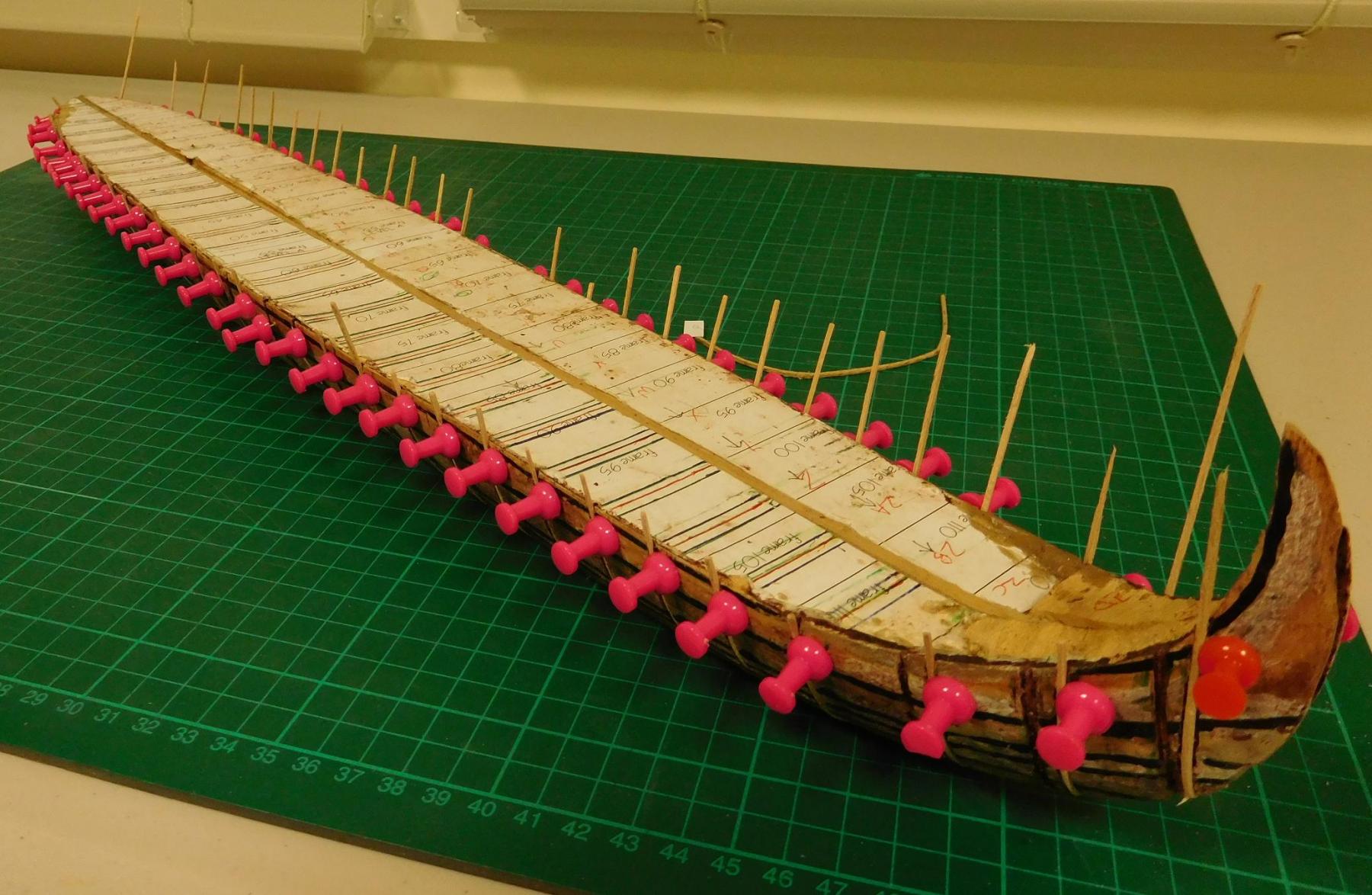
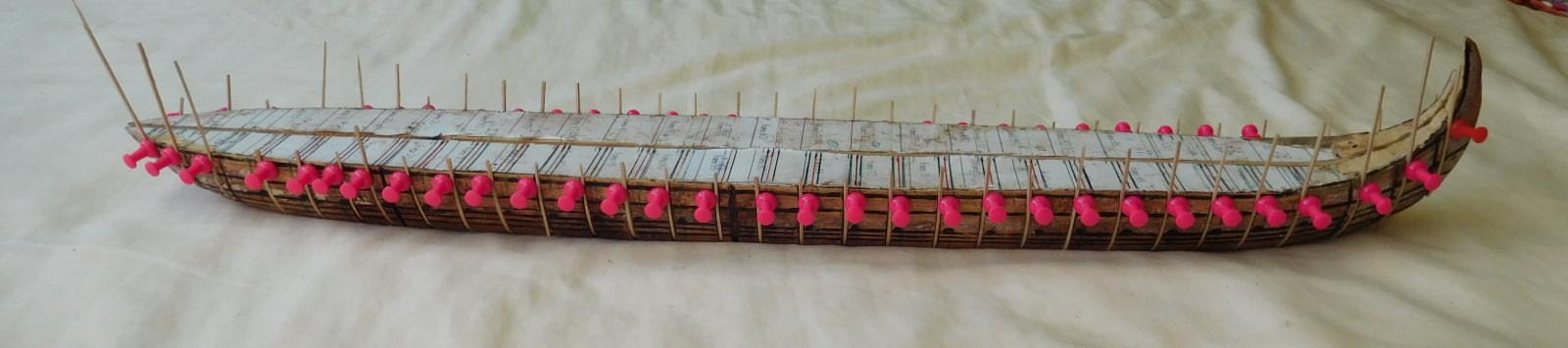
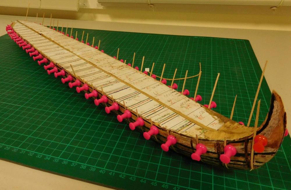
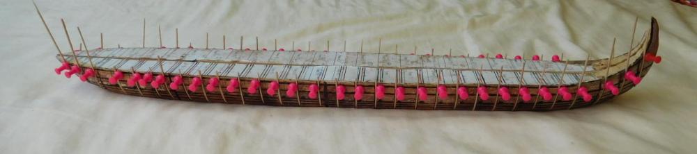
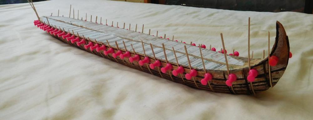
Johann I used pushpins on my own dromon build and they worked a charm! Thanks for the inspiration. And Mark, thanks for the tip about drilling holes to take the pins. It worked wonderfully. (I drilled 60 holes 1mm diameter and only broke one drillbit). Steven
-
I've now cut and soaked and bent into place 30 new frames. Copying the technique Archjofo used for for La Créole's boats in his build log, I managed to do as many frames fixed with push-pins in an hour as I did previously in weeks with a pair of clamps. So, thanks for the inspiration, Johann! One thing I particularly like about this forum is the helpfulness and ideas from other members, freely given. It means you don't have to keep re-inventing the wheel when a problem new to yourself comes up that someone else has already solved in their own build. There are a total of 120 frames for this dromon. So I'm halfway there. I'm just waiting for these to dry into shape and I'll make another 30, and then 30 more. I'm much happier with this rate of progress. Steven
-
Agreed. But I think somewhere on MSW there are a couple of logs, or perhaps tutorials, which deal with the problem of making sails look realistic (though this kind of sail is, admittedly, an extreme case). It might be in "Masts, rigging and sails". I seem to remember being pretty impressed with the solutions some members came up with. Aha! Found it! It's at http://modelshipworld.com/index.php/topic/9979-your-best-sail-cloth-and-technique/ And particularly look at JerseyCityFrankie's build log for the Victory (linked in his reply on the second page). Hope this helps. Steven
-
That's your decision of course, but it would be wonderful to see that enormous mainsail with the wind billowing it out. One of the really characteristic things about this type of ship which distinguishes it from any other kind of vessel, and of any other era. Steven
-
Such a beautiful build, so beautifully carried out. A privilege to watch it take shape. Steven
-
That is so impressive. And seeing the machinery in its place in the hull is a special treat. I really enjoy clicking onto your build and seeing what progress you've made this time. Steven
-
That might be worth considering, and though the dromon has no tumblehome, it has an equivalent in the fore-and-aft direction with the curve of the 'tail'.So I have to sort of rotate the hull fore and aft when I take the it off the plug. If there are grooves in the plug there's more chance of the frames jamming in the when I do that. On the other hand, I'm thinking that I really have to get my wales shaped now rather than after I've got rid of the grooves. They're thick enough and the frames are so thin that if the wales aren't properly shaped they'll force the sides of the hull inwards. And for the same reason maybe I need to make and position all my frames before I put the wales on. This is one of the problems of being something of a newbie - not enough experience with the problems that are likely to crop up, and not enough experience with working out solutions to them beforehand. I get a bit terrified that I'll do something irretrievable that ruins everything and have to start all over again. Still, that's part of the journey, isn't it? Steven
-
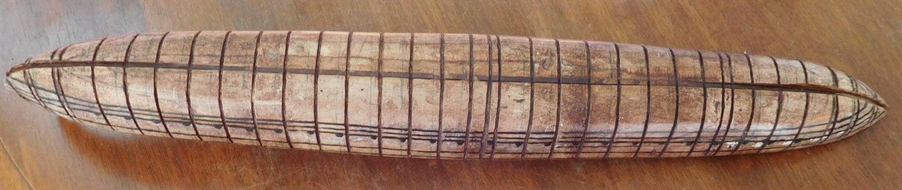
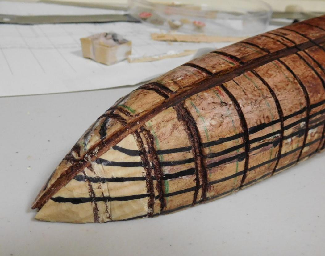
I've come to the opinion that I was on the wrong tack (pun intended) putting the frames in grooves in the plug when I'm planking - I think it's just asking for trouble. I believe there's a very good chance the frames will get jammed in the grooves and refuse to come out when I try to remove the hull from the plug. Also, having the outside surface of the frames flush with the edge of the plug multiplies the chances of accidentally gluing the frames or the planks to the plug, no matter how much wax or other kind of resist I put on the plug. My doubts were confirmed when I experimented with putting a wood strip the same size as a frame into a groove and dropping in some glue. I had to carve the strip out again - it stuck like dog poo to a shoe. It's a rather extreme experiment - worst case scenario - but finagle's (or Murphy's) law applies - if something can go wrong it will. I had been thinking of some way of using cling wrap as a back-up to keep things from sticking together, as some other modellers have done, but of course it would be difficult to get it to go into the grooves. I finally decided the best thing to do is to shave the plug down level with the bottom of the grooves, so the frames sit proud of the plug. It also allows me to use cling wrap. It's more work, but I think in the long run it's the best idea. I've made a start and the pine of the plug carves down surprisingly well, using my old mate the Stanley knife. I'll have to sand it smooth when I'm finished of course. The dark wood is the original plug (turned brown with shoe polish I used as a resist). The lighter bit is where I've shaved it down. And fortunately the brown shoe polish leaves a line in the wood which shows where the groove was, and where the frame needs to go. I cut down between only one pair of grooves at a time. This allows me to re-draw the lines of the wales and the locations of the oarports bit by bit so I don't lose them. I think having the grooves helped when I was bending the frames to shape. It helped them stay in place on the plug. And I think for something like a longboat there probably wouldn't be any problems using this method. But for something with as many frames as the dromon (and with a complex shape as well, especially at the stern) they are likely to cause too many problems.