
MORE HANDBOOKS ARE ON THEIR WAY! We will let you know when they get here.
×

kees de mol
-
Posts
796 -
Joined
-
Last visited
Reputation Activity
-

.thumb.JPG.4d3261ccae06041fa7cc2933fb43d577.JPG) kees de mol got a reaction from Ondras71 in Wilhelmina VII (KW140) 1914 by kees de mol - Scale 1/25 - Herring Lugger
kees de mol got a reaction from Ondras71 in Wilhelmina VII (KW140) 1914 by kees de mol - Scale 1/25 - Herring Lugger
In the past few months I managed to build some new parts for the herringlugger.
-
 kees de mol got a reaction from flying_dutchman2 in Wilhelmina VII (KW140) 1914 by kees de mol - Scale 1/25 - Herring Lugger
In the past few months I managed to build some new parts for the herringlugger.
-
 kees de mol got a reaction from FriedClams in Wilhelmina VII (KW140) 1914 by kees de mol - Scale 1/25 - Herring Lugger
In the past few months I managed to build some new parts for the herringlugger.
-
 kees de mol got a reaction from hexnut in Wilhelmina VII (KW140) 1914 by kees de mol - Scale 1/25 - Herring Lugger
In the past few months I managed to build some new parts for the herringlugger.
-
 kees de mol got a reaction from Dubz in Wilhelmina VII (KW140) 1914 by kees de mol - Scale 1/25 - Herring Lugger
In the past few months I managed to build some new parts for the herringlugger.
-
 kees de mol got a reaction from Vladimir_Wairoa in Wilhelmina VII (KW140) 1914 by kees de mol - Scale 1/25 - Herring Lugger
In the past few months I managed to build some new parts for the herringlugger.
-
 kees de mol got a reaction from YankeeD in Wilhelmina VII (KW140) 1914 by kees de mol - Scale 1/25 - Herring Lugger
In the past few months I managed to build some new parts for the herringlugger.
-
 kees de mol got a reaction from Mark Pearse in Wilhelmina VII (KW140) 1914 by kees de mol - Scale 1/25 - Herring Lugger
In the past few months I managed to build some new parts for the herringlugger.
-
 kees de mol reacted to the learner in Pelikaan 1999 by kees de mol - FINISHED - scale 1/75 - Dutch Beamtrawler
Well done! With this Covid 19 thingy it has given me lots of time to peruse build logs that I have nither had time for or that did not pique my interest. Again, well done!
-
 kees de mol got a reaction from coalman in Armed Launch by mobbsie - FINISHED - Panart - 1/16 - Small
Very nice build of this kit. Looks more like scratch building
-
kees de mol reacted to DocBlake in Hannah by DocBlake - 1:32 Scale - Plank-on-Frame - Admiralty Style
Finally completed all the frames. They are not sanded, beveled nor treenailed. There are over 300 parts making up the futtocks of the frames: 23 full frames, and 11 pair of half-frames and cant frames. All of boxwood. I wore out a dozen scroll saw blades cutting through that stuff. Fortunately the blades are cheap: about $0.50 a piece. The last photo shows a closeup of one of the full frames. I didn't use the Hahn method of cutting them out. All frames were constructed using individual futtocks assembled over a drawing of the frames. It IS possible to get tight joints between the individual timbers using that method.
-
-
kees de mol reacted to wefalck in GEMMA 1863 by Bitao - 1:36 - Legurian Tartane from Ancre plans
As a confessed tool-junkie I am always freaking out, when I see theses jigs and stuff !
These kitchen implements are marvelous and impeccable metalwork. Would you care to show us how you did them ? I gather the copper soup-pot is a piece of metal forming ? The stove is made from etched parts ?
-
-
kees de mol reacted to Schooners in Bluenose II by Schooners - Scale 1:48 - POF - from L. B. Jenson measured drawings - first POF build
Hi Joe,
I actually have a CNC machine and I have been wrestling with the idea of using it to cut the frames. I do not think it would be faster (each frame would have a unique tool path), but the resulting frame would be much nicer. They would be dead accurate as I could also machine the bevel on the outside of the frame. Since this is my first Plank on Frame model, I have a lot to learn about making the frames manually. I've always beleived that to automate a process, you need to be able to do it manually to completely understand what is involved. I've learned so much just by making these and each frame is made a little different as I learn. My table saw cannot repeatable produce thin strips of wood to the tolerance I would like. I built a thickness planer from a hand planner, but it is real finiky. Even dealing with the paper patterns was tricky. It took me a while to figure out the best method to adhere the paper pattern to the wood. I now use a glue stick and apply it judisiously to the wood, not the paper, as the paper gets soft, wrinkles and expands. So many things to learn.
I have created a DXF and PDF file for each frame, front and back. Below is an example:
Frame 26 front.pdf
-
kees de mol reacted to flying_dutchman2 in Zeehaen 1639 by flying_dutchman2 - 1:37.5 - Dutch Fluit of Explorer Abel J. Tasman
Measured many times the heights of the different decks.
Meaning of the colorful push pins:
Yellow and red is for the waterline.
Green and blue is for the lower deck
which will not be visible.
White and clear is for the main deck, and decks I don't know the names for.
This is the lower deck that will be completely hidden. I have put it in anyway because I will use it as a guide for the beams for the main deck and other small deck.
What is the deck called under the poop deck (where does that name originate from?).
Does the forecastle deck have a focsle on top of it?
Please feel free to set me straight or steer me to a location where all decks are defined on any ship. I have books that have some explanation of decks but they are not complete.
Thanks
Marcus
-
 kees de mol got a reaction from mtaylor in Zulu by Javier Baron - FINISHED - Scottish herring lugger
Beautyfull model!
-
kees de mol reacted to FriedClams in New England Stonington Dragger by FriedClams - FINISHED - 1:48 - POB
Thank you Johann and Hubert for visiting and the for kind comments. And as always, thanks to all for the likes and stopping by.
Trawl Winch Continued
Work on the trawl winch has been intermittent and slow, but here’s where it stands.
Some of the materials for the main section of the winch are shown below. The round disks that will make up the drum reels were cut from .02” styrene sheet using a paper circle cutter. The two hand wheels are 1:87 boxcar brake wheels injection molded in Delrin.
I decided to change the position of the bull gear from where I had it originally drawn. The gear has been moved from the end of the shaft to the center and now has a drum reel on either side. I did this after additional research convinced me this was by far the most common configuration of double drum winches regardless of time period. Once this fact penetrated my skull, I changed the drawings accordingly as shown below.
The drawing below describes how the drum reels are assembled.
I used solvent and CA gel to put these reels together - solvent when the pieces could be dry fit and gel where the parts were placed freehand and a brief window for position adjustment was needed. The shift ring slot will be cut later on.
The base frame is made from six pieces of styrene “I” beams. Cutting templates are drawn and the pieces cut.
The base frame construction is simple.
The frame is simple, but placing and riveting the corner angle iron plates was time consuming. I didn’t have any injection molded rivets that were small enough for this application, but the detail is easy to simulate. A rivet in the 3/4" diameter range was needed, so I heat stretch some plastic sprue frame to the diameter required. I hold the piece of sprue over a flame and when the middle begins to slump, I pull it apart (stretch it) to a fine thread. Somewhere along the length of the stretch will be the diameter I need and a one-inch section is found that calipers at .015". Monofilament fishing line also works great for things like this if the right diameter is in your tackle box.
The angle iron (and "I” beam) is styrene strip material from Evergreen. This structural shape material is a real time-saver if one of their available dimensions matches what you need. Here I’m using angle that is .060" (1.5mm) per side. That scales to 2.88" in 1:48 and is close enough to the 3" I was looking for.
Now it’s just a matter of drilling holes into the angle iron, gluing the end of my stretched plastic into the hole and trimming it with a slight reveal sticking out. I use a piece of brass shim stock as a height gauge to trim them off. I could round over the heads with fine grit paper - but my sanity is more important.
Some rivets were placed along the upper I-beams. Bolts and plate washers hold the base frame to the deck.
Pillow block bearings are made from copper tube and .010" styrene. There are two layers of styrene, one under the bearing and another wrapped over the top. The main shaft is .070” diameter brass rod.
In my parts stash I found this white metal gear. It is about the correct diameter and thickness for the bull gear so I’m going to use it as such. I cleaned it up and drilled out the hole for the shaft. The lower portion didn’t cast very well and is missing teeth, but I’ll rotate that to where it won’t be seen. A drum reel disc is shown as a relative size comparison.
A section of angle iron will be bolted to the I-beam base to support brackets for the brake wheels and clutch engage levers. The brackets are made from .020” x .040" styrene. The clutch lever bracket gussets are .010” material.
I’ve started on the clutch levers and yokes, but there is still a lot left to do - brake pads, pinion shaft, main winch head, frame and sheet metal guard for the auxiliary winch head, etc. And of course, the coloring and weathering.
Thanks for stopping by.
Gary
-
kees de mol reacted to FriedClams in New England Stonington Dragger by FriedClams - FINISHED - 1:48 - POB
John, Keith, Mark, Moab, Jim and Alexander - thank you so much for the kind remarks and continuing interest in my model build. I truly appreciate it. And thanks to all for the "likes" and for swinging through.
Here's a short update on the beginnings of the trawl winch.
I’ve spent an honest amount of time digging up details for a winch to go on this model. Like the gallows frame, I didn’t find a standard "this is what everybody used" winch. If I could time travel back to southern New England in the 1920’s, I’m sure I would indeed find boats using standardized equipment. Hardware and especially machinery such as a trawl winch were most likely purchased from marine distributors or direct from the manufacturer. It seems unlikely a winch would be built locally. Fisherman needed a trawl winch that worked flawlessly and was practically indestructible. And repair parts had to be available off the shelf to the get the boats back up and running quickly.
It would be great to have model numbers, catalogs, and exploded views of these winches, but I have none of those things. But the few drawings I do have include block outline dimensions of the winch and period photos show me what the winches looked like. So along with materials of more recent trawl winches, I have enough information to construct a winch that is at least historically honest if not precisely identical.
These draggers were small boats and their gear was sized accordingly. Below is a plan view of the winch I drew up for this model. Though small, it is actually larger than some I have seen. Notice the auxiliary winch head at the upper left in this drawing. It is driven off the main shaft with a sprocket and roller chain.
Here’s a small winch in place on a 1940s dragger.
And here is how I will position mine on deck.
These winches were pretty simple and consisted of drum reels with adjustable drag brakes and a clutch to engage them. Below is an end view of a 1960-ish trawl winch showing the clutch lever, the hand wheel for brake pressure and a winch head on the end of the main shaft.
Here is my version of it.
And then a side view.
This winch has no automatic mechanism to spool the cable evenly onto the drum as it is being wound. This was common on these boats and may be because the reels were quite narrow and therefore spooling unnecessary. Also, on many of these boats the cables wind/unwind at a very steep angle directly to the towing blocks, so if any spooling was needed it might have been done manually with steel push bars. The image below shows the steep take-off angle of the winch to the towing blocks. Also, I like this photo because it shows a net heavy with catch almost pushing the rail of this little dragger under water.
Below is a photo crop of a 1970s Cape Cod Eastern-Rig fishing boat. I wanted to show this image because it is the only one I've seen showing the use of steel bars to guide the cable onto the winch reels. Notice that the foot of the bar is placed into a wooden plate with sockets providing a choice of leverage positions.
In 1:48 the winch for my model will be a little over 1-1/8” by about ¾”. In the next post I'll make up parts and put it all together.
Thanks for stopping by and have a wonderful new year.
Gary
-
kees de mol reacted to FriedClams in New England Stonington Dragger by FriedClams - FINISHED - 1:48 - POB
Thanks to everyone for looking in and for the likes - I appreciate it.
Gallows Frame
This model represents a fishing boat typical of its type in the 1920s. Details on boats from the 1940s or 50s may not be historically valid for the era of my model. I found this to be true when considering the gallows frame construction.
It is easy to forget that a technology as commonplace today as arc welding, really hasn’t been around for all that long. Even though the first U.S. patent for arc welding was awarded in 1890, it was still in its infancy in the 1920s and many important improvements were years away. Steel joinery in the 1920s was mostly riveted, bolted together or forge welded. So construction of the gallows for this model will be riveted I-beam, angle iron and boilerplate - nothing welded.
After looking at many gallows frames, I came to discover that no two are alike unless they were on the same boat. Evidently, there was no “Acme Gallows Frame Company" and every port had its own millwrights/smiths constructing frames for their own local needs. But the frames generally fall into two basic styles – the inverted "U" and what I call the three-piece Stonehenge. The photos below show these two styles. I apologize for the poor quality of the images.
With some uncertainty I decided on a modified Stonehenge design. One criteria for the frame was that it be strong enough to support both towing blocks. Most trawl fishing boats carry two frames - one for each block, each towing one door (otter board). Photos of 1920s Western-Rig Stonington boats are rare and ones detailing trawling hardware are all but non-existent. But this photo (1950s?) shows what I believe makes realistic mechanical sense in terms of size and heft for a two-block frame.
I drew up the frame below using the above photo as a guide to what I wanted the end result to look like. The overall dimensions of the frame and the size of the steel used to build it, came from referencing photos of newer boats and a drawing of a 1920s auxiliary fishing schooner.
The towing blocks in the drawing may seem quite large, but it matches what I found were actually used. The pulleys alone are 12” in diameter and had to handle both wire cable and chain. Consider the strain these blocks had to withstand reeling in tons of fish in a net that trailed a mile behind the boat. The forces on the blocks, frame and the boat in general must have been enormous when the net gear snagged ledge or rock outcrop. But still, when I get around to making the blocks, I’ll scale the size back if they just look too large.
I then pull apart the drawing and make cutting templates for the individual pieces.
The frame I-beams.
The gusset plates and angle iron.
And finally the top frame head plates and base. All the small center marks indicate rivet or bolt locations.
The pieces are cut from styrene and a dressers' pin is used to mark the rivet/bolt locations.
The only fussy pieces to cut were the two head plates. Double-sided tape was placed on the sheet styrene and the template placed on top of that, then cut through with a scalpel and finished off with needle files.
Everything is assembled.
Holes are drilled at all rivet locations and styrene rivets glued in. The rivets scale to 1.25” in diameter.
The base is made and styrene N/B/Ws are added.
The frame is painted flat black enamel. This is only a base coat and additional washes and weathering will be applied later.
The frame base is stained and the hinge plates and nuts are painted. This also is just a base color.
Here the frame is temporarily placed on the base. Why the builders of these gallows went through the trouble of making them hinge and swing down flat is a mystery to me. In every photo I have seen of these frames they are shown chained, braced with iron pipe, and in one way or another reinforced to prevent collapse and from being torn off the boat. They appear to have never once been moved since the day they were installed. But there must have been a good reason for installing hinge plates.
Standing up and leaning forward in the dragging position.
Still to be done are the tow blocks and their attachment points on the gallows, some frame cleats and the rear brace that secures it to the mast. Also some chain reinforcing.
The last step will be to add a color wash then weathering and rust the whole mess. It needs to look worn and worked hard before it is placed on the boat.
Thanks for swinging by.
Gary
-
kees de mol reacted to FriedClams in New England Stonington Dragger by FriedClams - FINISHED - 1:48 - POB
Thank you Druxey, John, Keith, Chris, Jim, Michael and Tom for your fine comments and continuing support. I appreciate it.
And thanks to all for stopping in to take a look and hitting the thumbs up.
More Mast Stuff
Time to make up the mast navigation light and then place the mast on the boat.
The NAV light will be functional and the wires for the LEDs will be run through stainless tubing up the front of the mast. Half-inch trade size electrical conduit has an outside diameter of .84”. In 1:48 that is .0175”, and it just so happens that I have tubing with an OD of .018”. Running conduit for wiring in marine applications even back in the 1920s was probably a code violation and required something like mineral insulated cable. MI cable is round but somewhat smaller in diameter than conduit, so this tubing will pass for either, and I don’t know where to obtain tubing smaller than this anyway.
This stainless tubing is seriously small. It has a .002” wall thickness with a .013" ID. There is no visible seam and it is straight and smooth inside and out.
As I understand it, this tubing is manufactured for instrumentation and medical equipment and it comes in a variety of sizes.
Because the NAV light sits out from the mast, I need to bend an offset into the tubing. The wire sticking out the tubing is just a #34 magnet wire that I’ll use for pulling through the LED wiring.
The process of bending the tubing is simple. A stainless wire that nearly fills the inside cross sectional area is inserted into the tubing and this keeps the sidewall from collapsing during bending. The radius is obtained by wrapping it around an appropriately sized machine screw being careful to keep the tubing pressed tightly into the threads. The thread walls act as a bending shoe and helps keep the tubing from blowing outwards. The example bend below shows the stainless wire inserted and how much spring back can be expected in a simple 90-degree bend. The insertion wire was pushed in just far enough to clear the bend. Had I simply pushed the wire all the way in and out the other end of the tube, I probably wouldn't have been able to pull it back out.
Here is the problem with using small tubing like this for running LED wires. The wires on pre-wired LEDs aren’t fine enough to fit through the scale pipe.
Even the smallest LED with the finest wiring I have been able to find won’t fit through. It may look close in the image below, but it isn't. Even with the wires untwisted and straightened – no. And in some modeling situations, you may want to run more than a single pair of wires through the tubing.
So I solder my own surface mount LEDs with very fine wire, which also provides me with the luxury of deciding how long I want the leads to be without having to solder on wire extensions.
When first confronted with the task of actually soldering wires on to these tiny things, it seems utterly impossible, even ridiculous. But once I got my technique down, I found it surprisingly simple and that I could succeed almost every try - even with the smallest diodes. And the LEDs are literally one or two cents apiece when bought off the reel, so tossing away a few mistakes is painless.
I'd be happy to show the process on soldering these if there is any interest.
Below are the most common sizes I use. For this NAV beacon, I’m using the 0603 – the mid size one on the right.
The wire used is #39 gauge magnet wire. Including film insulation the OD is .0039”.
The LED is placed into the light fixture and filled with clear Gallery Glass. I previously made the light fixture when I made up the wheelhouse NAV lights - that process it is shown on page 3, post #86.
The bracket to hold the NAV beacon is made up from styrene, painted and attached to the mast.
The tubing is glued onto the mast and a couple of foil “pipe clamps” are added. The light wires are pulled into the tubing and the beacon is glued on to the bracket. The wire from the radio antenna is routed down along side the tubing. Some pigment power is used to repair and touch-up scuffed areas.
A quick check to make sure the thing still lights before the mast is set.
I am going to hold off on the boom, mast cleats and the mast coat until after the gallows and winch are made up and placed.
Next comes the gallows frame. Thanks for stopping in to take a look.
Gary
-
kees de mol reacted to FriedClams in New England Stonington Dragger by FriedClams - FINISHED - 1:48 - POB
Thanks to all for looking in and for the likes.
Hello Druxey. Yes I'll keep that in mind, but does your household qualify as a non-profit organization?
Hey Tom. That's a very cool and helpful site. Thanks for the link.
Some mast stuff
I want to begin building the gallows frame, but because it has a supporting brace that attaches to the mast, I need to make up the mast and get it placed first. But I won’t be stringing any stays or shrouds just yet.
The mast on this boat is 25.5’, which is slightly over 6.25” in 1:48. The boom is 21’. I mark and cut these two pieces from 1/4" dowel.
I used the brute-force method of a spinning dowel against a moving sanding belt to gain the taper required. You can reduce a ¼” dowel down to a toothpick in about 30 seconds with this approach - just be sure the dowel is spinning in opposition to the travel of the belt. As the pieces are being sanded to shape, I repeatedly check the diameter of the tapers at several points along their length with calipers.
Once I get close to the proper taper, I spin the dowel into incrementally finer handheld sandpaper. Finally I have two pointy sticks.
They were painted with acrylic paint. Many of these boats had bright orange or red masts. But many did not and were often painted either brown or black, which is good because I really didn’t want to paint it orange. I tried various values and mixtures of orange, but each time it made the boat look like a toy. So I ended up using burnt sienna and a little chalk for the lower mast and off white above the spreader.
I drew up the spreader and printed it out to be used as an assembly template.
It is made up entirely from styrene except for the center (hatched area), which is basswood. The four eyebolts receive the shrouds. The fore and aft stays will be connected to wire rope slings that wrap around the mast just above the spreader.
The mast gets a collar with gussets to hold the spreader. The band at the top of the mast will be part of an eyebolt assembly.
The spreader is slipped onto the gusset ring and glued down.
Holes for the eyebolts are drilled through the band at the top of the mast and the eyebolts are glued in.
The close-up below shows the top eyebolt assembly that will eventually receive stays/cables. The ring is made from wine bottle neck foil and the eyes are styrene. The top of the mast is under a 1/8” in diameter and this foil works great for these small applications - it lays down nicely, and the scale thickness is just right. Both the foil and eyes are dry brushed with Testors enamel “steel" and finished off with some pigment powder.
The eyebolts and the nut/bolt/washers shown in this posting are injection-molded styrene from Grandt Line Products. The eyes (which are not their smallest) are .05” OD or 2.5” in 1:48. The N/B/Ws are simply beyond ridiculously small and come in many styles and sizes. I use these miniscule styrene bits guilt free and without reservation because I simply cannot make them myself.
Down on the lower end of the mast are two bands that will be attachment points for the boom and gallows frame brace. The wider one on the left is for the boom and has a brass attachment tab facing aft to accept the boom. The tab is pointing down in this image and barely visible. Again, the bands are foil and nuts/bolts styrene.
I’ve added a radio communications antenna to the model. It is undoubtedly too short to effectively transmit given the modulation technology of the era, but it functions as a sort of visual stand-in.
Two-way radio antenna design is a deep dive into communication electronics and is subject to variables including transmitter power, frequency, travel distance and type of modulation. Modulation is key and refers to the method in which an RF signal (voice or data) modifies the characteristics of a steady state carrier wave. The carrier wave with the embedded information is what gets broadcast via the transmitter. Radiotelephone modulation in the 1920s was for all intents and purposes limited to AM double sideband w/full carrier (DSB-FC). This method is inefficient and requires considerable transmitter power and/or antenna. A much-improved and much less power hungry derivative of this type of modulation is single-sideband (SSB), but it wasn’t commonly available until the mid 1930s even though it was patented in 1915.
I’m beginning to babble which is a sure sign that I need to end this post.
So anyway, the aerial is made of magnet wire and stainless tubing and the strapping holding it to the mast is paper.
Thanks for stopping by to take a look.
Gary
-
kees de mol reacted to FriedClams in New England Stonington Dragger by FriedClams - FINISHED - 1:48 - POB
Thank you for the comment Jim and I'm glad you’re enjoying the log.
Yes, those foggy, soggy salt air mornings are tough on iron and steel. Thanks for your support Druxey.
I do take that as a compliment Greg, thank you so much.
But it reminds me of an incident from many years ago. I was displaying an HO scale diorama at a modeling show that depicted the surface structures of a hard rock mine – headframe, ore bin, hoist, boiler, etc. The structures were weathered and there was a good deal of rusty machinery and assorted debris strewn about. A guy who had been studying the model for about 5 minutes or so came up to me and flatly stated the reason I “junked it up" was because I didn’t have the skill to do it right. I said - well, OK then.
I understand this type of modeling isn’t everyone’s cup of tea, but it’s just a different style of modeling and it has been fun applying it to this fishing boat. Thanks again.
Oh come on – give the guy a break. He’s just trying to make a living in a difficult climate of rising fuel costs, diminishing fish stocks and increasing regulation. But I agree, he should fix the window and change the oil. Thanks for stopping by Keith - I appreciate your support.
Thanks Mark - that's the best outcome I could hope for.
Thank you Alexander – I appreciate your fine compliment and support.
Thanks for the complement Tom – sometimes you just get lucky.
And thanks to all for stopping in and hitting the "thumbs up".
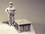
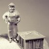
Here’s a small update on the galley stove stack and deck wash down hose.
First the stove stack. It is made from brass and styrene tubing that scales to about 5 inches in diameter – more or less.
The pieces are cut and glued together with epoxy, then primed and finally brush painted with black enamel. The goal here was to mimic black iron pipe. So before the enamel completely dried, I rubbed it down with a paper towel that had the slightest amount of paint thinner on it. I then added a bit of rust coloration to the underside of the “T" joint.
When I first looked at the close-up photo above, I noticed that the wall thickness of the styrene tubing is too thick and out of scale. I wear my OptiVisors the whole time I’m modeling and yet I didn't see this. The brutal honesty of macro photography can make you see things you really didn’t want to see - but it often shames me into going back and doing a better job. So I use a tapered round needle file and ream the ends of the tubing to a wall thickness that’s a little closer to scale.
And a bracket for the stove stack made from .005" brass shim stock and a couple of styrene bolt heads.
Next is the water shut-off valve for the deck wash down hose. It is meant to represent a 1” bronze globe valve, which is physically larger and can pass a greater volume of water than the typical residential style garden hose shut-off. It scales to just over 6” long and its larger size is advantageous in a couple of ways. First and most obvious is that it makes it somewhat easier to model even though its actual size is still just a tad over 1/8". Secondly, it will help in keeping it from getting visually lost as other details are placed near and around it, such as an overhanging rooftop dory, a life ring mounted above it, shrouds with wooden ratlines and so on.
The valve body was fashioned from a piece of scrap white metal. The bonnet and gland flanges are stacked bits of styrene and the hand knob is an injection molded 1:160 freight car brake wheel from Tichy Train Group. It was primed and then colored with pigment powders.
The hose is a piece of electronic silver solder. At .032” in diameter, it scales to about 1.5" in 1:48. It was pulled through steel wool a number of times, cleaned with alcohol and then blackened with Jax Pewter Black. The plus for using solder is that I could make it lay flat, look natural and it would stay put as I worked at forming it. The end of the “hose" was stuffed under a coil so I didn’t need to make a nozzle.
The valve and hose were then glued into place. From the early planning stages of this model, I had stuck in my head the idea of using a truck tire rim mounted to the pilothouse as a hose holder. But I have never seen any such thing in any period photo of these boats where a reel or holder was used. So, no tire rim – and it really is much easier for the crew to just toss the hose into a pile out of the way.
Thanks for looking in.
Gary
-
kees de mol reacted to FriedClams in New England Stonington Dragger by FriedClams - FINISHED - 1:48 - POB
Thank you Alexander, Dan and Patrick for your kind comments and support - I really appreciate it. And thanks to all for stopping by and smashing down on the like button.
Pilothouse Siding
It’s time to install the roof and siding on the pilothouse and glue it to the boat.
First, I thread the wires for the various lights down the interior of the walls and then glue on the roof. I glue it down in a way that I can crack it back off if I ever need to.
I then determine the size and quantity of wood needed for the siding and stick it down with double sided tape to a piece of waxed paper. The wood scales to 1 x 4". The basswood is stained with regular hardware store furniture stain.
Once dry, I paint the strips with an off-white craft type acrylic.
After about fifteen minutes, I pull some of the paint off with cellophane tape.
The siding strips are fitted and glued on as shown in the detail below. More weathering still needs to be done to reduce the uniform look of the siding, but this is a good starting point.
The two aft pointing floodlights are made up next. I used a pair of 1:48 truck taillight housings that I found in my junk box and attached them to brackets I made up from styrene. I soldered up and inserted #0603 warm white LEDs into the housings and used clear Gallery Glass for lenses. The escutcheon plates are punched from .008” tin.
The wires are run down the walls between the interior and exterior siding and the floodlights are glued into place.
Exterior window casings, shoe base and eave trim are added. Because the windows slide down into pockets, scuppers are needed to drain the pockets in storms and rough weather. The scuppers are cut from .032" O.D. tubing. The window facing forward requires two scuppers, one in each corner of the pocket. The P/S windows have only one scupper each, which are located at the lower aft corner of the pockets. Only one is needed on these side windows because the pilothouse has a 4-degree pitch to the rear. Oddly, old photos of these boats do not show drain scuppers on every boat, which makes me wonder where the water goes when a window is left partially open and water is sheeting down into the pocket. They must have drained to the bilge or out the side somehow.
The photo below shows the additional weathering applied to the siding. Weathered vertical surfaces typically display less damage at the top than at the bottom. Eaves and other protrusions provide some physical protection from the elements at the top of the wall, so paint survives there longer. But it is water that does the most damage. The bottom of the wall is the last to dry out as water runs down from above and keeps it wet longer. And the lower wall gets splash off the ground or in this case, the deck. Once water finds its way behind the paint, the wood begins to rot and the paint to peel.
To simulate this wear, I brush on additional paint at the top of the wall and in the somewhat protected areas up high between the windows. I darken the lower walls with a mixture of India ink and alcohol – about one part ink to three of alcohol. I also added some short subtle diagonal markings that run from the right downward to the lower left. I did this to suggest sleet/hail damage and a possible reason for the broken window.
This pilothouse is looking pretty beat especially when viewed against a clean white background. When viewed away from the background in an area where there is visual clutter surrounding it, it doesn't look quite so bad. So as I work on weathering, I keep checking it against a clean background to get a better sense of the level of damage I’m inflicting on it. It is easy to get carried away and it’s difficult to turn back.
Finally it is glued on to the boat. Some weathering of the deck will be required to make the pilothouse look like it belongs there - but that’s another time. And before the pilothouse is complete, I still need to add life rings, a roof top dory, a water spigot and hose for washing down the deck and maybe a grab rail or two.
Thanks for stopping by.
Gary
-
kees de mol reacted to FriedClams in New England Stonington Dragger by FriedClams - FINISHED - 1:48 - POB
Nice rust streaking Tom. The tanker looks absolutely real - nice work! I did know of the Weather Shop site and there is some amazing work to be found there. Thanks
I enjoy experimenting with little things like that, which is good that I do because my trash can is filled with them. Thanks for the comment Chris.
Wow. Thank you so much for the comment and for stopping by. I appreciate it.
And thanks to all for looking in and the likes.
Pilothouse Window Sashes
This short update describes the building and placing of the wheelhouse window sashes. It’s one of those grinds in modeling where a lot of time is spent with little to show for your efforts.
There are six window sashes to be made. They are approximately 3/8" wide by 7/16" tall. I already have drawings for these sashes but I check the individual window openings with calipers and adjust the drawing to the “as built” dimensions. With the corrected dimensions, I create templates for the sashes.
Each sash will be a sandwich consisting of a pane of glass between outer frames. So two frames will be required for each window sash.
Basswood that scales to ¾” x 2" is cut and arranged on the template.
A drop of medium viscosity CA is placed at each joint where it seeps down into the joint through capillary action. The frames are removed, trimmed and sanded.
A piece of glass is cut and glued between the two frames.
I use real glass instead of plastic film or acetate for a couple of reasons. First, it is perfectly flat and when you catch a reflection off of it, you can see that it’s flat. Acetate and other films can buckle or display waviness that the eye is quick at picking out. Second, you can scrape paint or adhesive off with the tip of a scalpel without scratching or deforming it. And some adhesives can cloud clear plastics in the surrounding area.
A pane of glass for a shed window is typically 1/8” thick. I am guessing that glass for a wheelhouse window is thicker than that – say 1/4". The glass I'm using here is manufactured as microscope slide coverslips. It is .13 mm or .0051” thick, which is very close to 1/4” in 1:48. These coverslips are available in 18mm x 18mm squares or 24mm x 50mm rectangles. They are easy to find on-line and inexpensive - less than 10 dollars US for a pack of 100 pieces. I bought mine here with free shipping.
Eye protection is crucial when working with this glass. A tiny fragment can chip off and fly – anywhere.
The glass is cut by lightly scoring it with a diamond point scribe and then breaking it over an edge just as you would with full size glass. The scribe must be held vertically, perpendicular to the glass, and only a single score along the glass is required. A gentle touch and light downward pressure is needed. After breaking a few pieces, the process becomes easy.
As far as the diamond scribe is concerned, a craft/hobby level tool is adequate. Most craft type scribes have an included tip angle of 90 degrees. More expensive and sharper scribes have tip angles of 60 and 30 degrees, but they are fragile and the tips easily broken. I know this first-hand. And straight-shafted ones are easier to use than the bent ergonomic handle models.
And then some punk pitched a rock through the window. When working with glass, there is an irresistible urge to model the “broken window.” It is somewhat cliché, but I can't help myself. This poor little boat is taking a beating anyway, so what’s one more indignity?
The process of breaking a window is a hit or miss affair (no pun intended). Sometimes it works - sometimes not. At this scale it is necessary to build a perfectly good sash first then break it and hope the results turn out believable. To tilt the odds toward an acceptable result, I score the surface where I would like the glass to crack then tap the point of my round needle file into the desired center of impact. If this were a larger scale, say 1:24, I would piece broken fragments together.
Have I mentioned eye safety?
This photo shows the partially open window. Photos of these draggers show window sashes that slide inside channeled pockets or dados with no surface stops visible. So I cut a slot in the jambs above the lowered sash to represent this detail.
Next, the roof goes on along with the siding and outer window casings. Thanks for stopping by.
Gary