

David Lester
-
Posts
678 -
Joined
Content Type
Profiles
Forums
Gallery
Events
Everything posted by David Lester
-
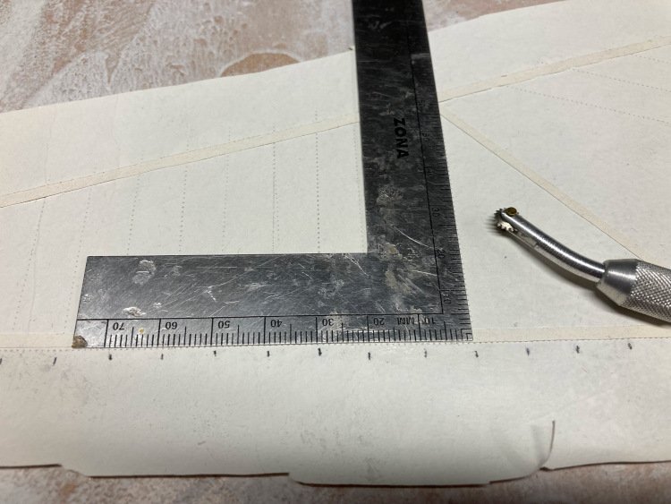
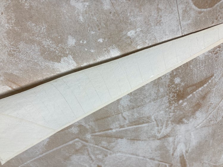
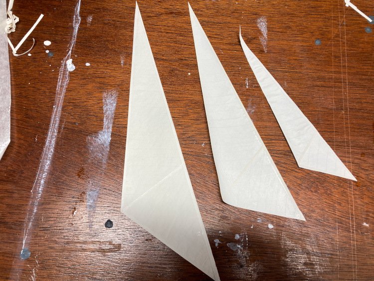
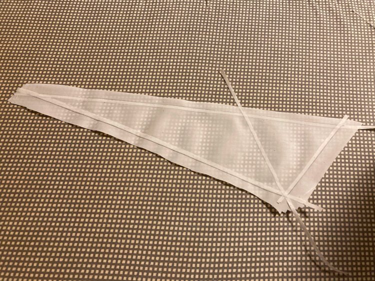
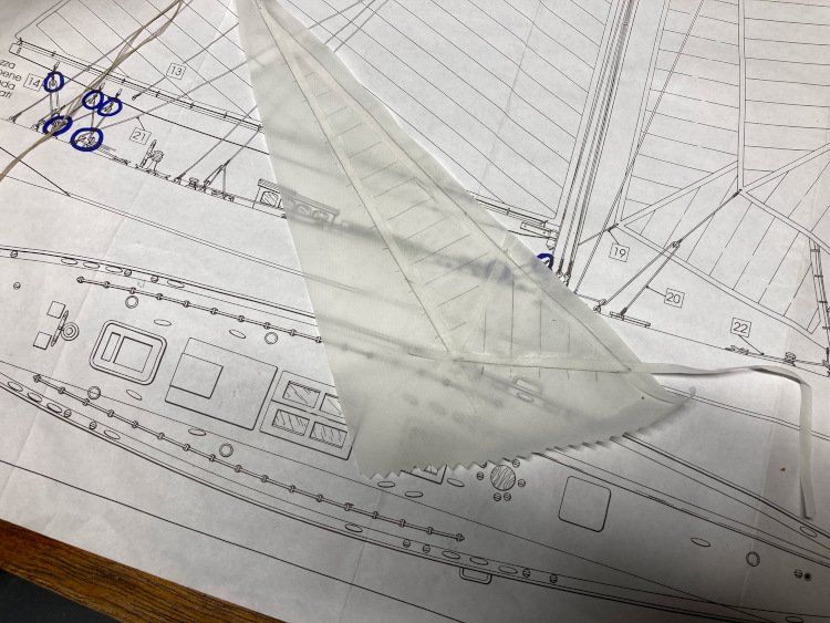
 Good Morning Everyone, I've made good progress on the sails. Roger, I appreciate your comment, and as a rule I prefer models without sails. However, I think this yacht needs the sails, and it's a good opportunity for me to experiment with them. As I mentioned earlier, I found the kit provided material all but impossible to work with, so I had ordered some silkspan which arrived on Monday and I spent much of Monday and yesterday working on the the sails. I found the silkspan easy to work with and I believe I will have an acceptable result. Following Tom Lauria's method, I painted the silkspan with some acrylic paint. When dry I pressed it flat with an iron. Tom mentioned using something called dry waxed paper. He doesn't mean regular waxed paper, which would leave quite a mess. Instead of dry waxed paper I used parchment paper which we already had and it did the trick. It can withstand quite a bit of heat and it protects the silkspan. The next step was to cut out the sails. I made cardboard templates, but here I had to differ from Tom's approach, as I ruined my first sail. He outlined his sail with a pencil, but when I did that, as soon as I ran glue along the edge for the reinforcing strip, the pencil just smudged and made a mess of the sail. The next time I ran my pounce wheel along the template and this cleanly laid out the sail. I marked the template where the seams go, according to the plans and transferred those marks to the material, but outside the edge of the sail. Then it was a a simple matter of cutting out some reinforcing strips and gluing them along the edges of the sail. When it came to marking the seams, I differed from Tom again. He recommended drawing on pencil lines to show the seams. However when I did this, the line looked too heavy and seemed, to my eye at least, to look too much like a pencil line drawn on the sail. I know that others have tried actually sewing seam lines on, but I wasn't about to get into that and it often looks over scale in any case. So, I turned to the pounce wheel again and marked the seams with it. I'm pretty happy with the result. It shows up just enough, not so much as to be distracting, but still noticeable. I then flipped the material over and applied the reinforcing strips and "seams" to the other side and then cut the sail out. I then ironed the sails again, between two sheets of parchment paper, and I think they're finished. There are four sails on this model - the three small ones which I've done and one large one. Unfortunately, I will have to re-do it as it's marked out with pencil and isn't too clean looking. Fortunately, I ordered enough material. Anyway, that's my first experience using silkspan and I have to say that I found it to be a very nice product to work with. Thanks again for looking it. David
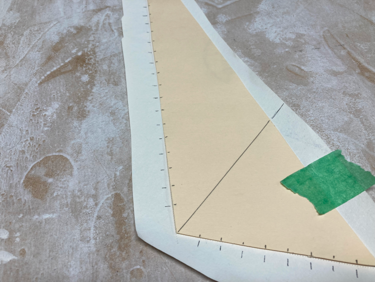
- 31 replies
-
- 12
-

-
- Shamrock V
- Amati
- (and 2 more)
-
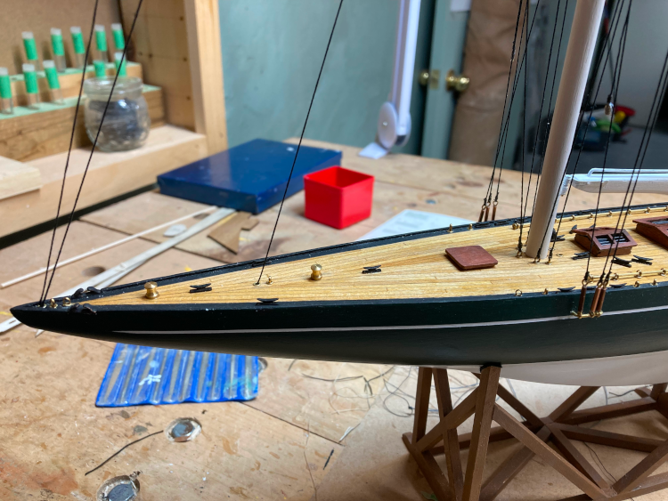
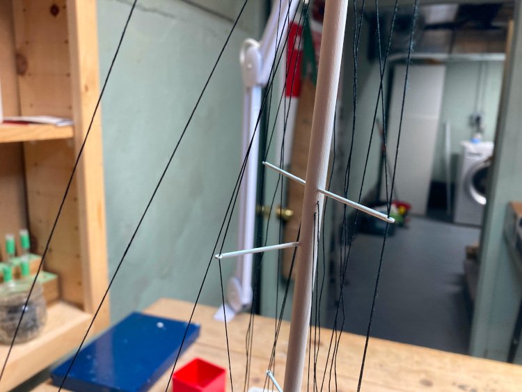
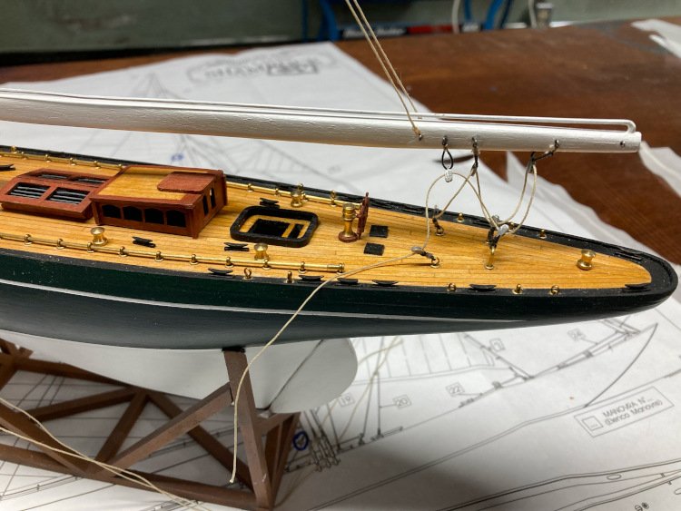
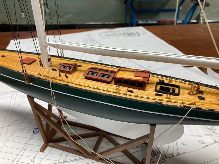
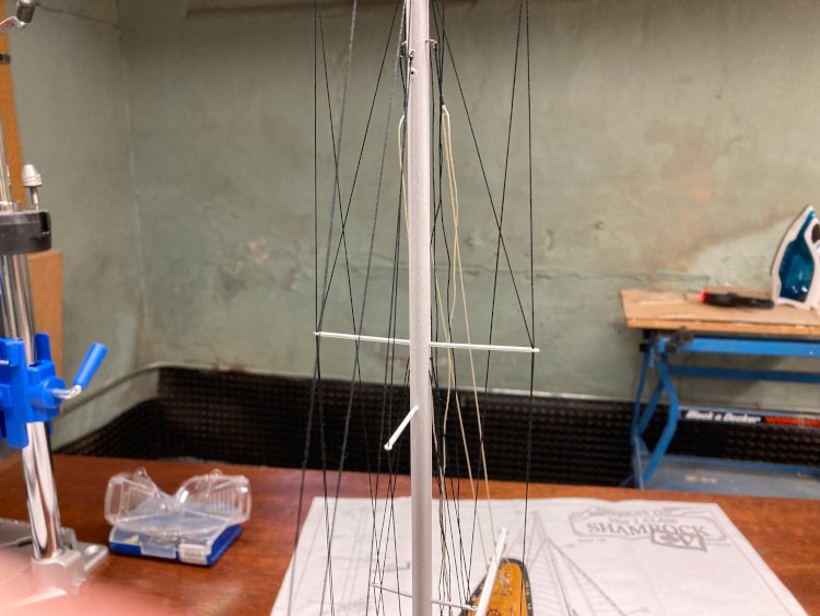
Good Morning, A little more work on my Shamrock to report. I've finished up the deck details and have a good start on the rigging. The rigging on this model is minimal and quite simple to do. Also the instructions are quite clear so not too big a challenge - I've upgraded the blocks to internally stropped ones, from BlueJacket. This is as far as I can go until I add the sails. Most of the running rigging must be added at the same time as the sails. I'm finding the sails to be a very big challenge. The kit provides some material that seems quite suitable to me. It's a very fine synthetic fabric which does not seem to be over scaled (to my eye at least.) But they only give you just barely enough, certainly not enough for a practice round. I followed the instructions in the kit and also followed someone's Youtube series about his build of the Amati Endeavour yacht, which appears to use the same fabric and method. His seemed to turn out beautifully, but it's lot easier watching it being done than doing it! The approach is to coat the fabric with a 50/50 mixture of white glue and water. Cut out narrow strips to represent the reinforcing at the edges and other points and glue them on. Then cut the sail out. I have two problems, which aren't actually well reflected in my pictures below. First it's very difficult to get the sail to lay flat and not wringle. The first one below is by for my best effort and I even think it could pass as acceptable, however the others are not nearly as good. The second problem is that I underestimated how easily this gluey fabric would pick up every last bit of dust and dirt in my shop. As a result the sails, in addition to being wringly, also look pretty dirty. I think it's possible that I could manage to get an acceptable set of sails using this method, but I would need about three times the fabric to allow for do-overs. So, I have ordered some silkspan from BlueJacket and I'm going to have another go at it, this time following Tom Lauria's approach as he outlined in one of his videos. It's quite similar to the first method I tried, but he coats the material in paint instead of glue. I think I've ordered enough to allow at least one do-over. If I can't get a decent job with the silkspan, I'm not sure what I will do, but I remain optimistic! Once I conquer these sails, the build will be virtually finished. Thanks for checking in. David
- 31 replies
-
- 10
-
-

-
- Shamrock V
- Amati
- (and 2 more)
-
Hi Dave, Your stern windows look great. I'm glad you were able to bend the stern piece with success. I don't believe it's identical to the one on my Mamoli Rattlesnake, but it's very similar. Mine had to be bent to fit too, but I wasn't quite as successful and broke it. However it wasn't really a problem (it actually made it easy to fit) and I was able to fit it without the repair showing up I know there are many different ways to paint this kind of part, but here's a method that I discovered in a BlueJacket newsletter and I found it worked really well for me. https://myemail.constantcontact.com/News--tips--and-happenings-from-BlueJacket-Shipcrafters--Inc-.html?soid=1105166336677&aid=EmTQZTxYvqc David
-
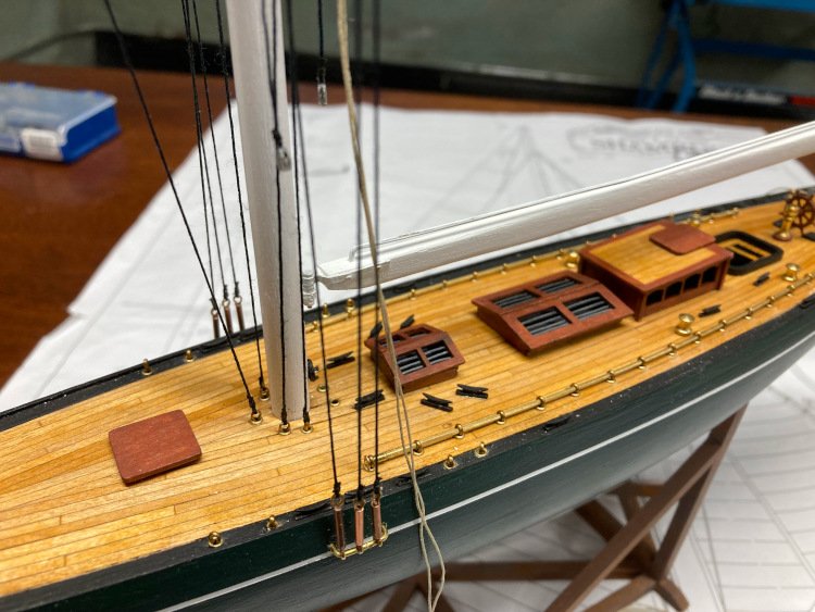
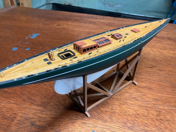
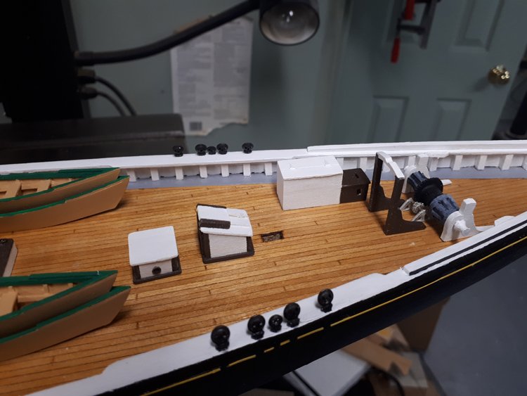
I've added most of the deck fittings. First thing was drilling the many holes for the brass bushings and other fittings. It's hard to believe but there are over 70 1mm holes on this deck! Of course, as we all know, the drilling is pretty easy, it's the locating that's the hard part - The rest of the furnishings are minimal and very easy. I had already assembled the various structures - This is not too complex a build. I actually think I spent more time painting the hull than I have on everything else to this point. So next up is the mast and rigging. It doesn't look to be too difficult and the plans and instructions are quite clear. Thanks again for checking in. David
- 31 replies
-
- 8
-
-
-
- Shamrock V
- Amati
- (and 2 more)
-
Thanks for the comments, guys. I've learned the hard way how important it is to get the masking tape really well sealed. I have a pick from an old set of picks for Christmas nuts. The rounded smooth back side of the pick is perfect for rubbing the tape down really well. Then before I apply the second colour, I seal the edge of the tape with a couple of coats of paint the same colour as the paint that's under the tape, then if there is any bleeding, it won't show up and it blocks the second colour from bleeding through at all. It took a few coats of paint to cover and I only did one side at a time, so it seemed a long wait to find out if I had sealed the tape well enough or not. That finish is just brushed on, but the paint went on really smoothly and evenly. I hesitate to tell you what kind of paint it is, because it won't seem sophisticated enough, but it's just Americana Satin Acrylic. I think this paint is made for craft projects and folk art and that type of thing, but I was really impressed with how nice it is to work with and how smoothly it went on. It also seems to have a really hard finish. The level of sheen seems just right to me too. Many of the model paints only come in flat or glossy finishes and it's hard to find something in between with a soft sheen. There wasn't a very dark green available, so this is one they call 'Beret Green' which I mixed with some black. David
- 31 replies
-
- 5
-
-
- Shamrock V
- Amati
- (and 2 more)
-
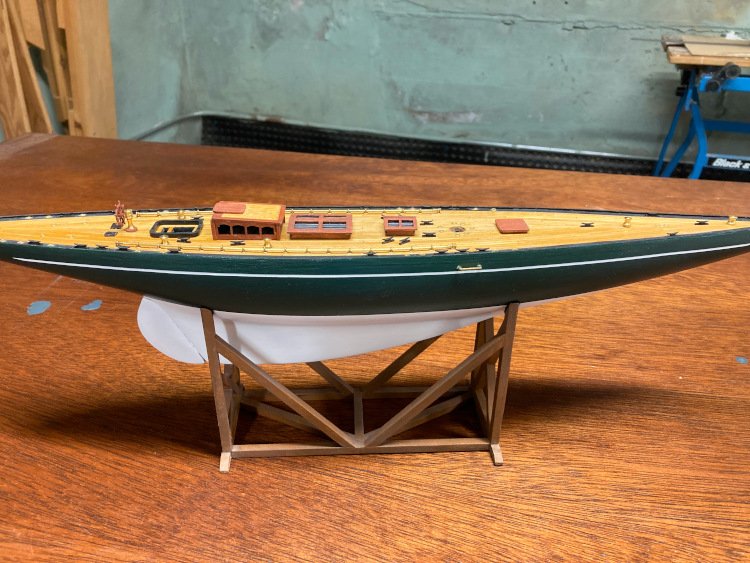
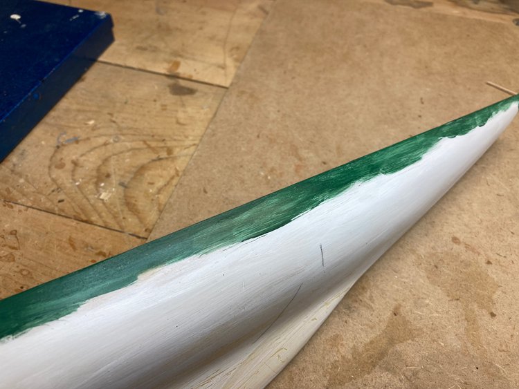
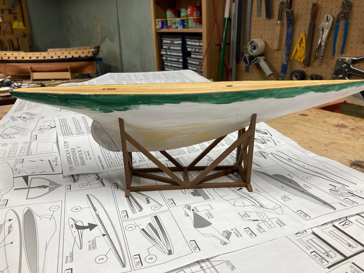
Good Morning All, So I've been spending quite a bit of time getting the hull painted and it was a bit of a process arriving at a finished hull. The first question was what colour should it be? There just aren't many resources out there. I cannot find any pictures at all of the original yacht. There are pictures of the current Shamrock, but it's a totally different vessel than the 1930's one. The kit includes pictures of two different finished models. In each case the whole hull is green, with a broad white stripe at the waterline In this one the whole hull is a dark green, with a slight bluish cast Here it's a more yellowy green Initially I painted the hull to match the first picture above, the darker green, which I managed to match quite well and for some reason it looked terrible. Then I rediscovered the picture with the lighter green inside the box and thought that it might look better. Before changing it, I decided to do a little more research on line and became quite confused as to what to do. The current version of the Shamrock is a very dark green with a dark contrasting lower hull, with a broad white stripe at the waterline and a narrow stripe (maybe yellow) higher up - I discovered a number of different pictures of models of the Shamrock out there but no two of them were the same - green tops, black bottoms - white tops, green bottoms - green tops, red bottoms - green tops, copper bottoms etc. etc. However, this one I found by model maker John Adela (ageofsail.net) caught my eye - So I consulted with my friend, whose model this is. (I keep forgetting that I'm not getting to keep this one.) He decided that since we don't really know how the original was painted, it was more a matter of choosing the look he liked best and he settled on the colour combination by John Adela. So I stripped my first paint job off the hull and started over and the results this time are much improved - For some reason, this was the hardest waterline to draw. I simply could not secure the model well enough to draw the line in the way I usually do. I usually place the hull upside down and use some cedar shims to make the hull level side to side and to adjust the height at each end. I clamp a pencil to a square and draw the line on. It's worked easily every time - but not for this hull. I had no better luck with the hull right side up either. In the end, I marked the point at the bow and stern where the waterline would terminate and then placed a strip of narrow masking tape on the hull and continually adjusted it until it looked ok to the eye. This took quite a bit of adjusting and readjusting. When I was happy with it, I drew a pencil line along one side of the tape. By this time the masking tape had been man-handled a lot, so I replaced it with a new strip placed along the pencil line. This worked, but I wouldn't want to have to do it this way every time. So next up is touching up the black around the edge of the deck and then finishing the deck details. Thanks for checking in and Happy Thanksgiving to all my US friends! David
- 31 replies
-
- 10
-
-
-
- Shamrock V
- Amati
- (and 2 more)
-
You can buy Admiralty Paint red ochre individually at Cornwall Model Boats. ( https://www.cornwallmodelboats.co.uk/acatalog/admiralty_paints_water.html ) Whenever I need something small like that, I just make up an order of staples - masking tape, drill bits, xacto blades etc. until I have a large enough order to justify the shipping cost. David
-
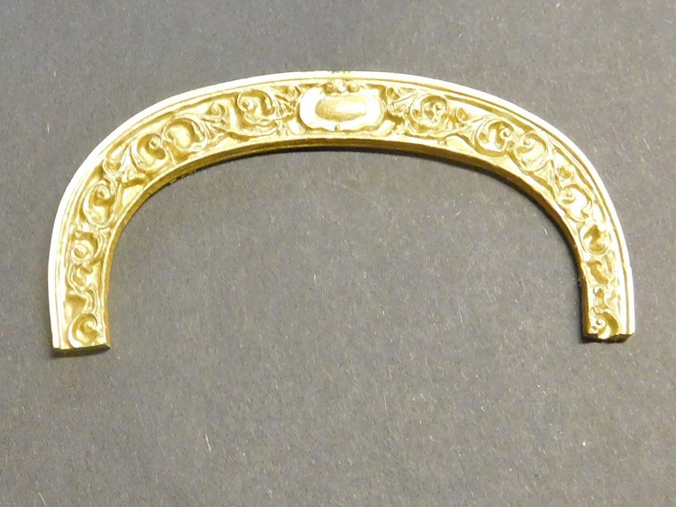
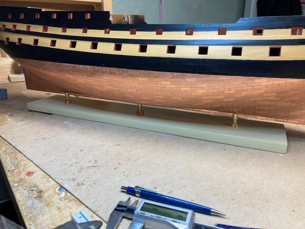
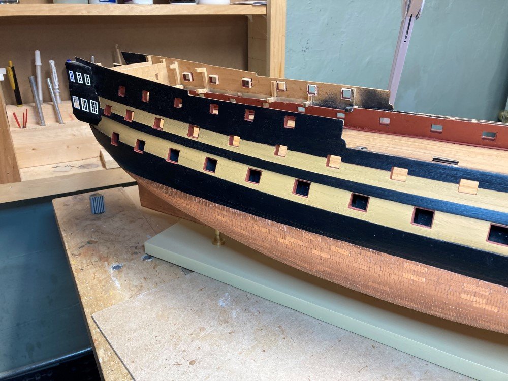
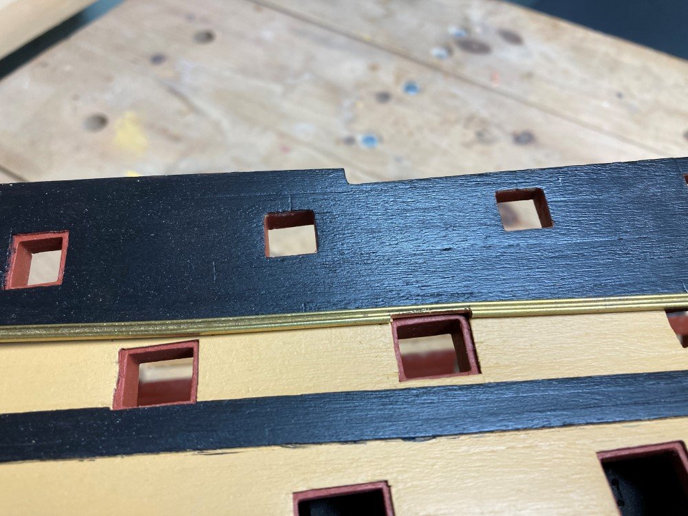
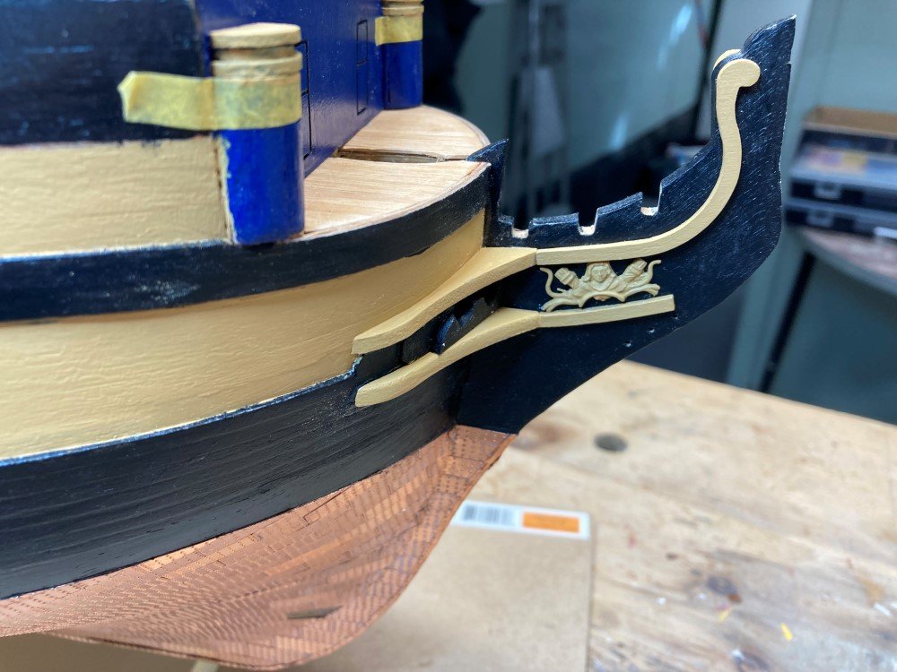
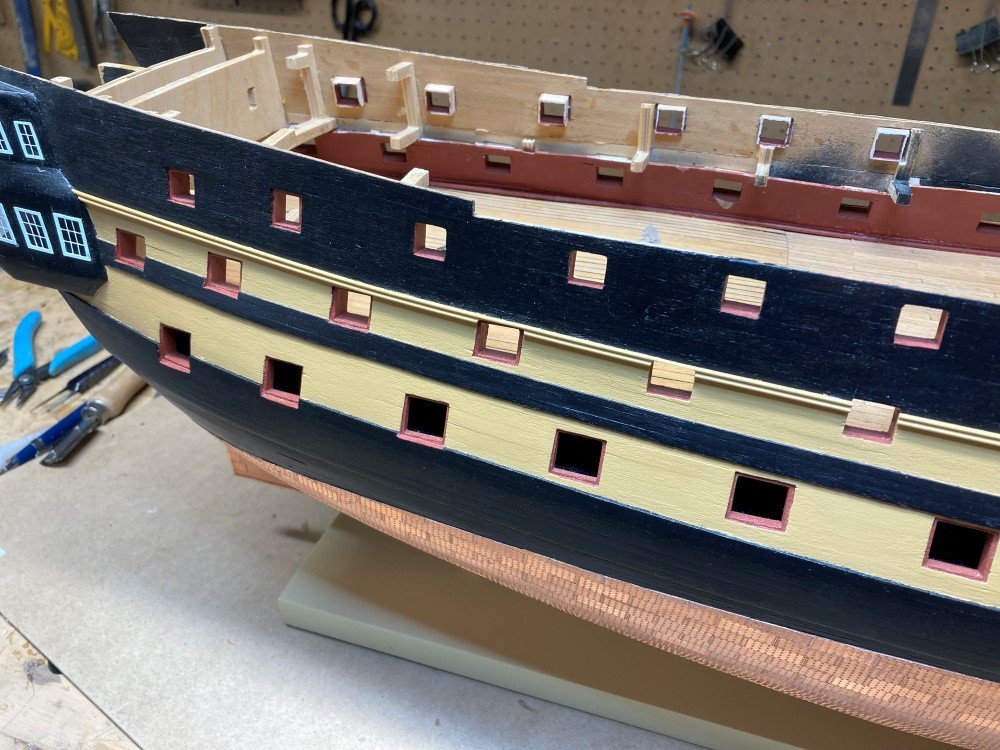
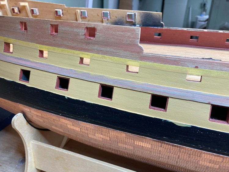
I've been working in a very disorganized way, turning my attention from the stern to the bow to the hull and back again. Here are a few pictures of what I've been doing. Here I've added the gallery windows and have done some more painting on the hull. I created this elaborate system for organizing and painting the windows, but if I had it to do over again, I'd have just glued them in place unpainted first and then painted them after. Despite my careful application of several coats of white paint, once in place they still needed touch up and I had to file away paint from the corners of the muntins. So I ended up effectively painting them in place anyway, and it was surprising easy to do. Cutting in around the edges was not hard. I think I could have saved myself a lot of wasted effort. It's starting to look like the Agamemnon - Here I'm adding the first of the moldings. I was a bit intimidated at the prospect of working with these brass strips and I contemplated replacing them with Evergreen styrene strips. In the end, I decided against that as they can be very hard to glue neatly and I thought they would be hard to keep in a straight line. As it turned out, the brass is not difficult to work with, is very easy to glue in place and it looks pretty good. Here's the first one painted - Here is the first stage of the bow details - That's all for now. Thanks again for checking in. David
-
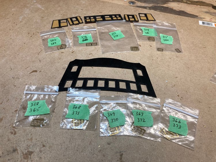
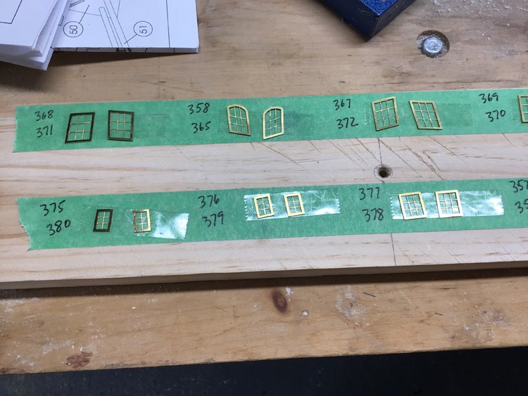
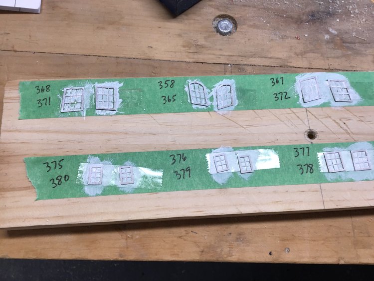
Good Morning, I have not been working on my Agamemnon for a while, but found some time this week, (when I was not raking leaves!) I always find that at certain stages of a build, I become paralyzed and am not sure what to do next. It seems that every time I set out to do one thing, it's dependent on another being done first. I'm at one of those points with Agamemnon. It seems there are any number of ways I could go and I'm not sure what's best - add hull details, add deck details, work on the stern, work on the bow? In any event, before I can work on the hull details, I need to do some more painting, so I've been doing that, but it's fairly slow going. I always find painting the top edge of the wales very hard to do. I haven't started that in the picture below, and depending on how it goes, you may or may not see a picture of it. 😄 Similarly, in order to work on the stern area, I need to have the windows ready. This is a huge job in and of itself. There are 38 of them. Each has to be fitted to a specific location and it's pretty important to keep them organized. These windows are amazing, very detailed and have a good side, where the muntins are slightly recessed from the frames. They fit their locations very well, but nevertheless still need a bit of filing to seat properly. (I think that's partly due to the black paint slightly filling the rabbet where the window sits.) I divided them up into pairs and worked through them a pair at a time. I filed them to fit properly and then placed each pair in a small bag, numbered to correspond to its location. I wanted to paint them all at the same time to avoid going through the multi-step process repeatedly, so I placed strips of masking tape on a scrap piece of wood. Then I numbered where each pair would go and added a piece of double sided scotch tape. Working in pairs, I washed the windows in some acetone and after they dried, placed them on the double sided tape, ensuring they were right side up. They hold really quite well and this way I can get them all painted at the same time, without too much fear of mixing them up. One coat of white on so far. I think two or three coats will do it. So that's where I am so far with Agamemnon. Not a lot to show, but there is a ton of slow going detail to work through. Thanks for checking in. David
-
I used CA glue. It was either Gorilla Glue or Bob Smith. I have both, but I don't recall which I used in this case. David
-
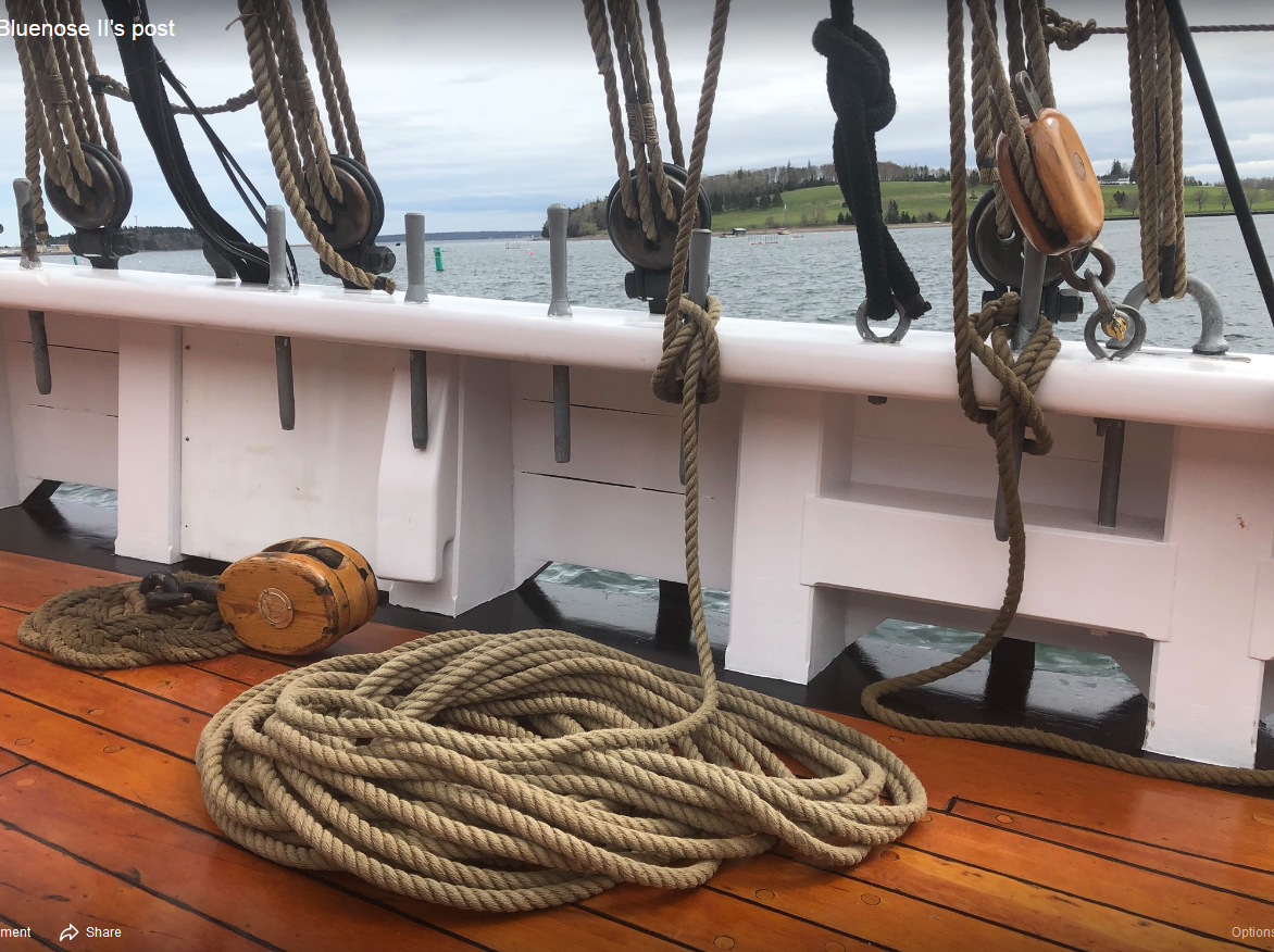
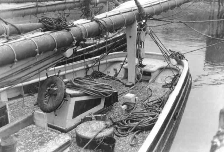
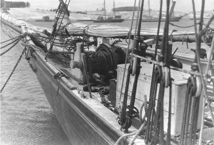
I don't know for a fact that they were painted, Allan, but it's my best guess based on the old black and white photos of the Bluenose. In the first picture of my post above, comparing the blocks to the parts that we know were white, such as the rails and then to the boom, which appears to be natural, I think they look white. In any case, rightly or wrongly, painting them white was an easy approach when using cast metal blocks. It's easier to paint a white finish than a natural looking wood finish.😀 On the Bluenose II however, they are definitely natural. Those Syren blocks would look great finished like this. David
-
Hi Gregg, The Model Shipways plans for the Bluenose indicate that all the blocks were internally stropped and any pictures I've seen would appear to confirm that. If you are thinking of replacing the blocks anyway, why not use BlueJacket's internally stopped blocks. I used them on my Bluenose and I think they're great. They're made of cast metal and need to be painted. From the old photos, it appears to me that they were white, so that's how I finished mine. If I remember right, I ignored the sizes of the provided blocks and took the sizes from the plans and then approximated as closely as possible from what was available with the exception of the 3/32" size, which are very small and difficult to use. I sometimes found it necessary to drill out the hole of the strop and it was almost impossible to do on this size without "tearing out" the strop. For these ones I ended up substituting 1/8" blocks and look fine and they were wasy to work with and of course, anything over 1/8" presented no problem at all. You can also get internally stopped blocks from Syren, but I don't believe they are available in small enough sizes. Also, they appear to be so beautiful that I didn't have the heart to paint them, so I opted for the cast BlueJacket ones, which need to be painted, so they seemed like the perfect choice. They come with a becket, which you don't always need, so when that was the case, I just snipped it off and filed that end of the block smooth. With respect to deadeyes, I also used BlueJacket's. The lower deadeyes are attached with a "shackle" type fitting and I knew I could never get a satisfactory result trying to duplicate that with wire and/or brass rod, so I opted for the BlueJacket cast ones and I was quite happy with them. So that's one suggestion. David
-
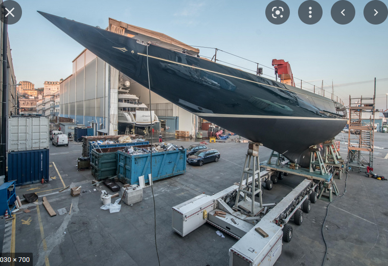
Thanks guys. Bob - they are beautiful. I've never built a model like this before, but I'm finding it quite interesting as I've been reading a little bit about the America's Cup yachts from this period. It's hard to find photos of them though. The Shamrock is still in existence (or at least another one called Shamrock) but it's so dissimilar that pictures of it are not of any use. While the Amati kit seems to be of decent quality, I'm pretty sure it's a very simplified, stripped down version of the real thing. While it appears to be accurate as far as it goes, I suspect that there is much detail omitted. It's fun nevertheless. David
- 31 replies
-
- 4
-
-
- Shamrock V
- Amati
- (and 2 more)
-
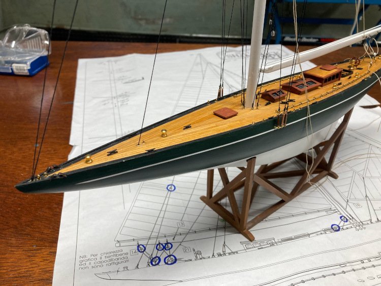
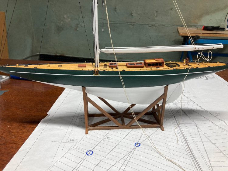
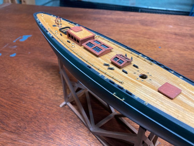
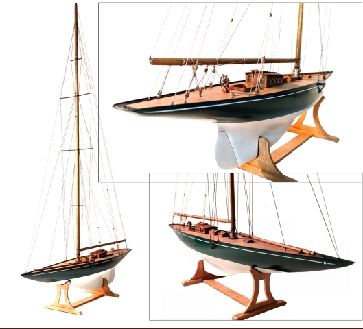
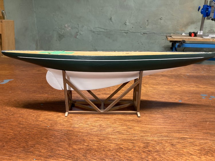
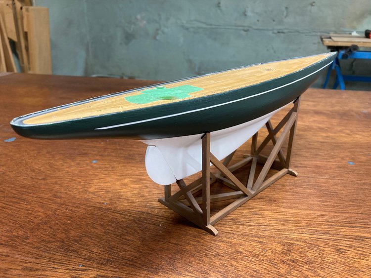
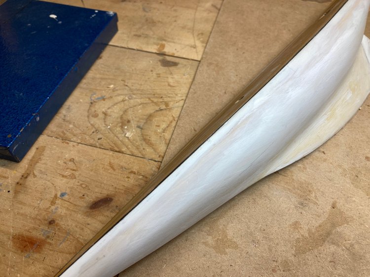
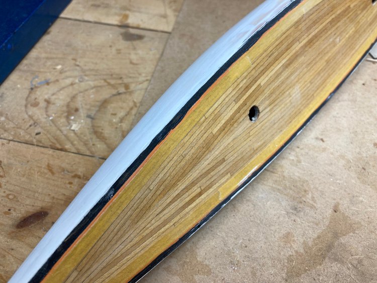
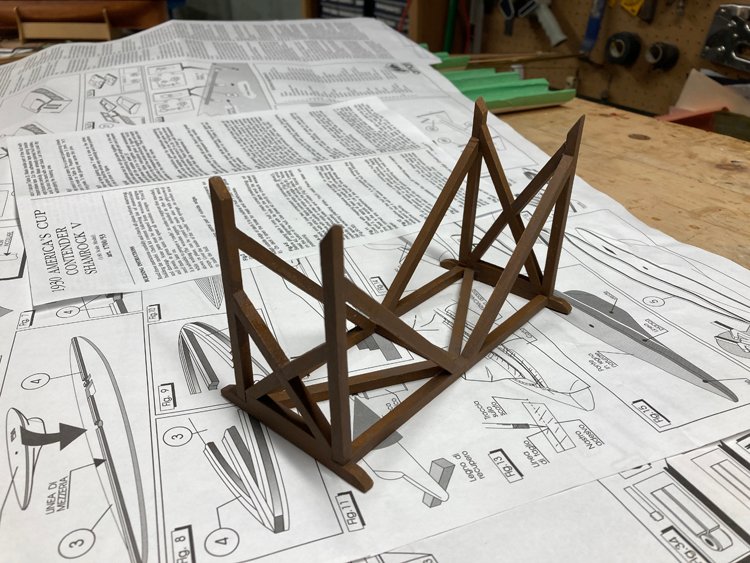
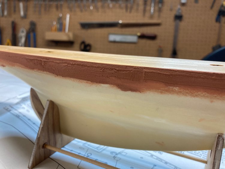
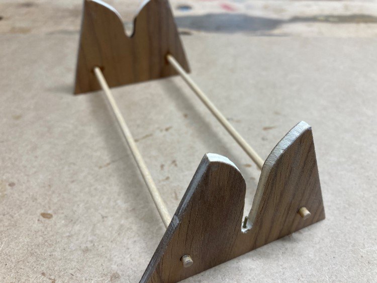
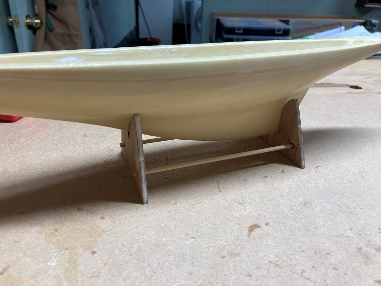
Good Morning, I've been focusing on two things over the past few days - First, I've been working on the upper edge of the hull. As I mentioned before, the sub deck is glued directly onto the hull and then the deck planking on top of that. It's necessary to get a smooth upper edge to the hull which is supposed to meet crisply with the deck. I had filled the edge with some filler, but before working any further on that, I added the black painted border that goes around the deck - Then I sanded, refilled and painted the top of the hull - It's not hard to do, but it takes quite a few coats to get it smooth. It will appear to be prefect in one light, then as soon as I adjust the light, I can suddenly see all kinds of imperfections. I applied one quick coat of green to the top and this seems to make it easier to find the tiny imperfections. It's all but finished now, just some very minor touch-ups needed. The other thing I've been working on is a stand. I thought I would use the one provided in the kit, but it's really pretty flimsy, doesn't really fit the hull very well (despite my efforts to modify it) and it isn't very attractive. I was at a loss as to what a suitable stand for this yacht might look like, but then I found something that I thought was suitable in forum member Ekis's build log for his Endeavour J Class. I though it was quite handsome, so I set out to try to do something similar. In the end I came up with something that is a little less sophisticated than his and perhaps not quite as beautiful, but it's simpler and I think it does the job quite acceptably. It was a bit challenging without a plan to work from, so I just took a trial and error approach. There seemed to be too many variables and no fixed starting point. So I just started in and quickly learned that all I should expect from my prototype was that it would have suitable overall measurements and not to worry about how it looked. I basically just slapped the bracing etc on. Once I had an established model to work from, ie its height, width and length, I then built a new one, this time paying attention to how it looked. I used some 3/16" square stock from my stash. It's not perfect, but I kinda like it and it's a definite improvement over the little kit supplied one. Thanks again, David
- 31 replies
-
- 10
-
-
- Shamrock V
- Amati
- (and 2 more)
-
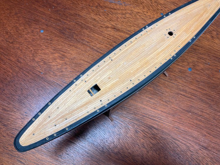
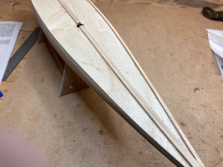
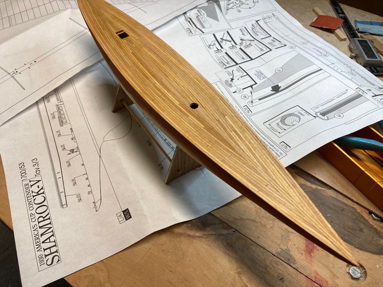
I've added the deck planking, and it's a bit different than that of other models I've done. The planking is square - it's 2x2 mm. The first step is two strips laid down each side of a centre line. Then the outermost plank and it's simply laid flush with the hull. From here it's a matter of laying the planks working toward the centre. The planks were easy to install and they take the curve of the hull without any soaking or pre-bending. On one side of the centre line, the planks went out even and the last one fit in width perfectly. On the other side of the centre line, the last gap was just a bit too big and I finished it off by adding a last 3/64" plank from my stash. It went very quickly as the hull is only just over 17" long, so there really wasn't much area to cover. Quite a bit of sanding was required. There was a lot of variation in the thickness of the planks, but with 2mm to work with, there wasn't much fear of sanding right through. This was a very easy deck to sand - it's flat and there are no sides of the hull to interfere. In fact I used an electric palm sander. I applied one coat of shellac to seal the wood before adding the filler at the point where the hull meets the deck. I have applied the first coat of wood filler ( or stucco, as the Italian instructions call it.) I think it will likely take at least one more coat before it's ready to paint. So that's my progress so far. With a pre-made hull, it really doesn't take very long to get to this point. Once the filling is done, then I think it's time to paint the hull Thanks for looking in, comments and likes. David
- 31 replies
-
- 8
-
-
- Shamrock V
- Amati
- (and 2 more)
-
Thanks Mike - the people I made it for picked it up this morning and they seemed very happy with it. They had been looking at the ones you can buy in gift stores, so they were surprised and pleased by the level of detail that this kind of model has. I packed it up in a box with styrofoam, so it will travel safely. They had asked me what I wanted to build it for them and I said only the cost of buying the kit and stand. I didn't want anything for building it. In fact it was a treat having the joy of building it and not having to worry about where to put it. They did bring me a gift however - a $100 gift certificate to the LCBO (provincial liquor store) so this was a win-win experience all around. Thanks again, David
- 43 replies
-
- 4
-
-
- Mayflower
- Model Shipways
- (and 1 more)
-
Fitting of combined lift and sheet blocks to the yard.
David Lester replied to DaveBaxt's topic in Masting, rigging and sails
Hi Dave, Good! Sorry, I called you Bruce instead of Dave. I mistakenly referred to the post directly above mine. David -
Fitting of combined lift and sheet blocks to the yard.
David Lester replied to DaveBaxt's topic in Masting, rigging and sails
Hi Bruce, I don't know if the technique I use is "correct" or not, but it gets the job done in a fairly tidy way. First I seize the lift block in the centre of a piece of line. Then I bring one of the free ends up, forming a loop and seize it to itself as well as the other line about 1/4" or so below the first seizing. This creates a gap in the middle for the sheet block and a loop at the bottom for the yard. I place the sheet block in the centre gap and snug the second seizing up against it, then place the bottom loop over the end of the yard and pull on the two ends of the line to draw it tight around the yard. I hope this is what you are looking for. David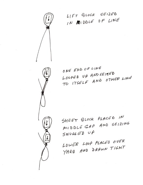
-
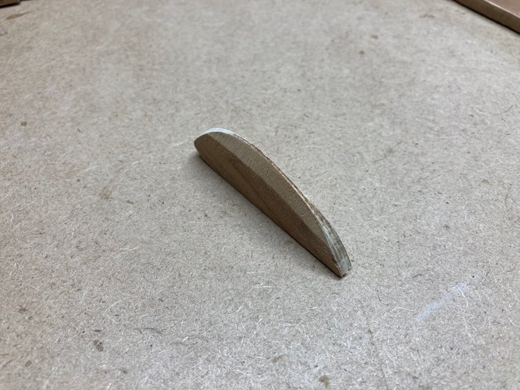
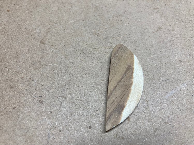
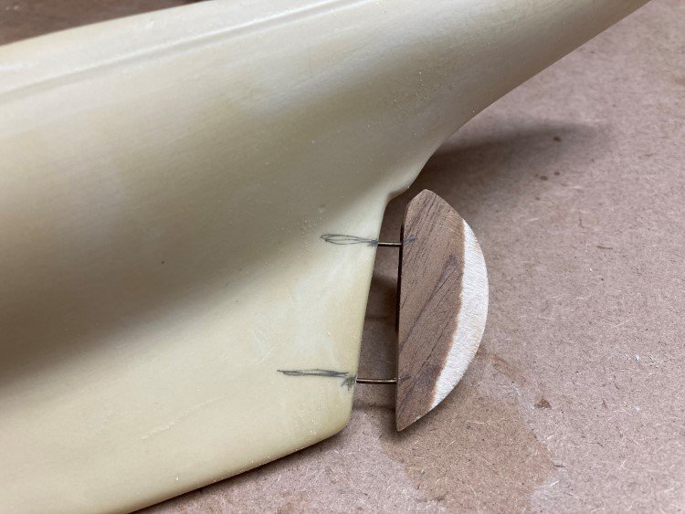
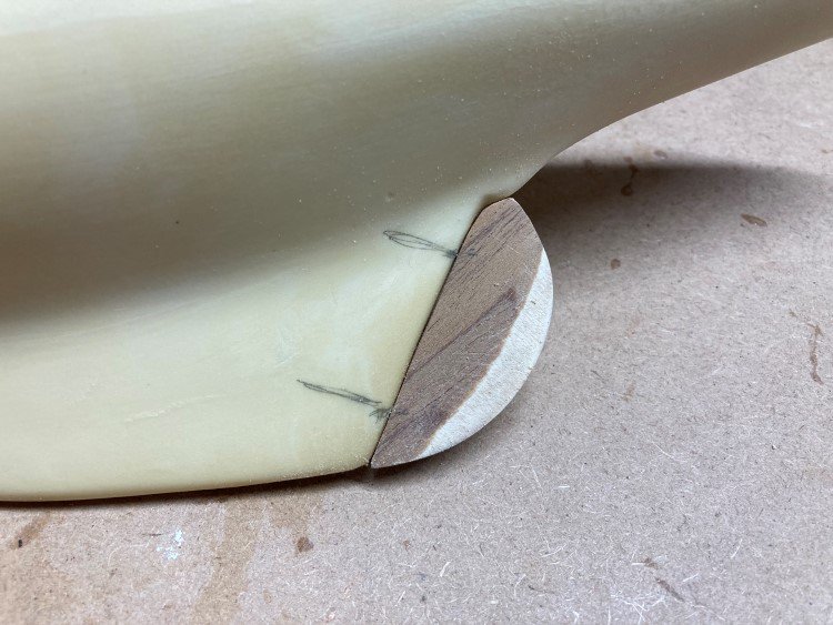
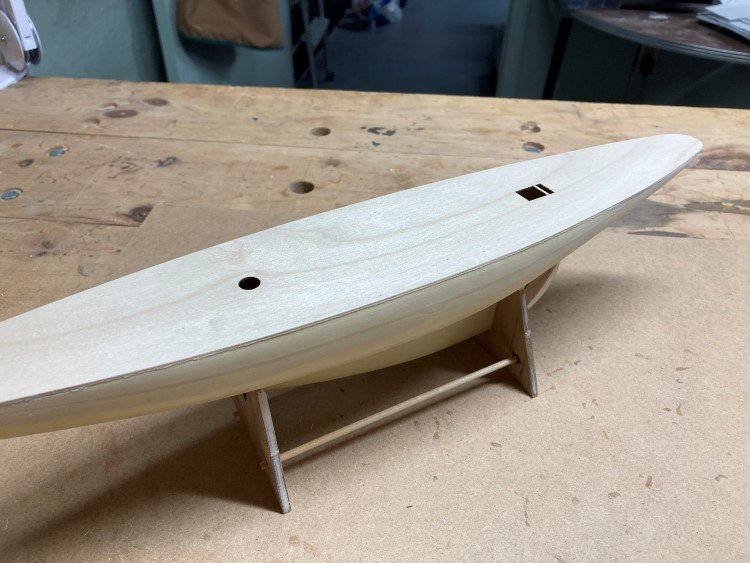
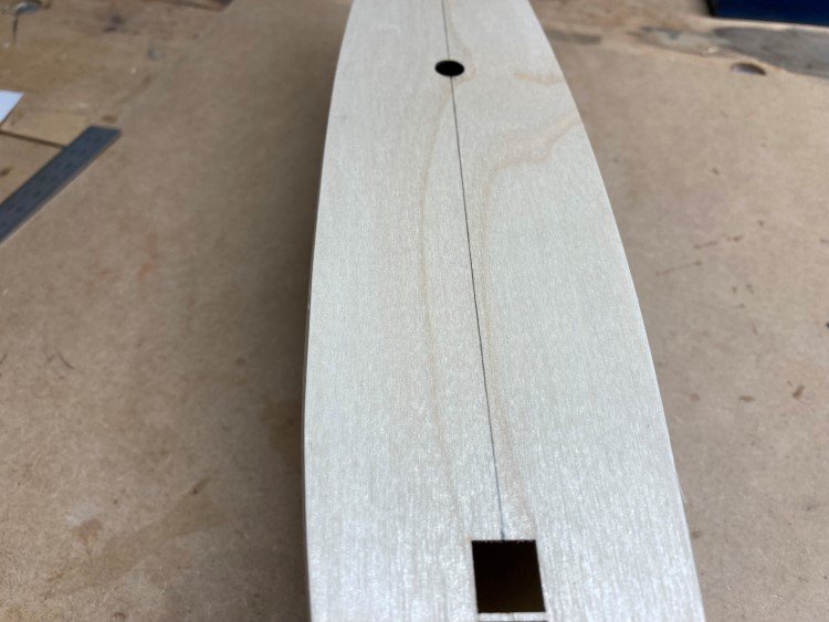
I started in last night and am beginning to get a feel for this kit. I noticed that the included stand needed quite a bit of tweaking to fit the hull correctly. I decided to tend to this first, rather than later after things are attached to the deck and the hull is painted. Both the model and the stand are very light in eight and it proved to be helpful to drill a small hole in the bottom of the keel and place a pin between the stand and the keel. The first item in the instructions is the rudder, which is made from some kind of plywood with a fairly coarse grain on the outer layer. The rudder needed to be tapered. A little more fine sanding and maybe even filling will probably be required. I'm going to leave that until I get one coat of paint on first, to better see what is needed. I could not imagine this rudder adhering well to the resin hull with some pinning - Next was the sub deck which just gets glued directly to the hull. There's a hole in the hull for the mast to sit in, so it was just a matter of putting the mast in place through the sub deck to line them up. The sub deck fits the hull beautifully. It was just ever so slightly oversized so that it could be sanded to perfectly match the profile of the hull. Centre line drawn and ready to begin the planking. The planking on this one is different than I've seen before. It's 2mm x 2mm basswood (or lime) and the planks are supposed to curve following the curve of the hull, not run straight. Because of this it's going to be necessary to work from the outside in, rather than from the centre line out. We'll see how that goes. David
- 31 replies
-
- 8
-
-
- Shamrock V
- Amati
- (and 2 more)
-
J Class Yacht Rigging Question
David Lester replied to David Lester's topic in Masting, rigging and sails
Thanks for the input, guys (and the stories too.) That's pretty much what I guessed to be the case. I don't think I'll try using wire for the standing rigging however; I'd never get it lay straight and even and I imagine just a slight touch might put a slight bend in it. I'll probably just end up using black line, but maybe I'll experiment a bit with a metal-like colour. Allan, thanks for the information about the NYYC model collection. I had a look at their website and I think That would certainly be a great place to visit, however, I don't see a New York adventure in my near future (let's be honest, I rarely leave the basement!) Thanks again, David -
I am launched into a new project building a J Class yacht for a friend (Amati Shamrock V) and I have a question about the rigging that maybe someone knows the answer to. The kit provides only natural coloured line (ecru, tan, off-white or whatever you want to call it) and the picture of the model on the box shows all of the rigging (both running and standing) done in this colour. Somehow this doesn't seem right to me. Since this is a 1930's era yacht, would it be correct to believe that the standing rigging would actually have been wire cable. Somehow that seems likely to me. Does anyone out there know? On my Bluenose model the plans stated that all the standing rigging on that vessel was wire cable and had serving. (I didn't have a serving machine at that time, so just ignored this and simply used black line.) If the rigging on Shamrock V is wire cable, is it likely to have been served as well? Somehow that seems less likely to me. Again, if anyone knows, I'd be grateful. If the standing rigging is wire cable and is not served, what do people think would be the best colour line to use for it. Simply black, or stick with the ecru line provided or would you do something unusual, such as gray. (I'm not going to try my hand at using actual wire.) Anyway, any thoughts you have would be much appreciated. Thanks, David
-
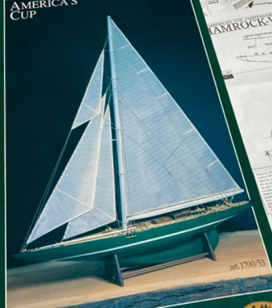
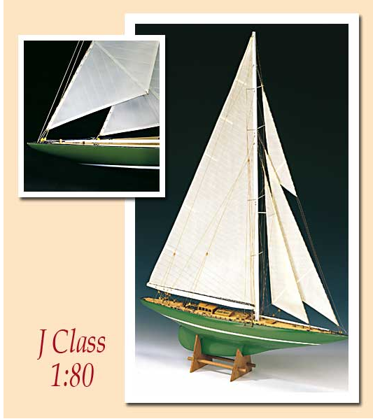
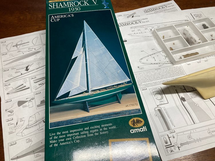
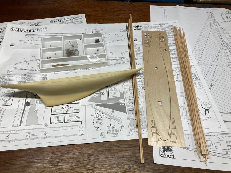
Hello Again, Well, I certainly didn't expect to be building a J Class yacht until yesterday when a friend called and asked if I'd build his Shamrock V for him. He has had the kit collecting dust on a shelf for many years and doesn't anticipate ever getting to it, so asked me if I'd build it for him. I have learned that Amati makes a range of America's Cup yacht kits, but the Shamrock V is one that has been discontinued. Since yesterday I have been poring over the kit. It will prove to be a relatively simple build, but appears to be a high quality kit. The fittings are excellent and the instructions and plans are very clear and easy to understand. (I do have a question about the rigging, but I'll ask that in a separate post under the right topic.) This kit has a pre-cast hull ( a type of resin, I guess) which will cut down on the amount of work needed considerably. I have never added sails to a model before, but I think this is one model that definitely needs them, so I'll be reading through everything I can find on making sails. The fabric provided in the kit is very fine and I don't think it will need to be replaced. Here are a couple of shots of the kit: So, an unexpected change of pace. David
- 31 replies
-
- 14
-
-
- Shamrock V
- Amati
- (and 2 more)
-
Thanks everyone for the nice comments. I really appreciate them. This was really just a diversion for me; I built it for a friend as a gift for her dad, but it turned out to be a very enjoyable project. James - good luck with your Mayflower; that's very interesting that your wife is a descendant. I think there were only about 100 or so passengers on the ship. It's wonderful to be able to trace the family line that far back, but even more so with such a rich history. You definitely need to be displaying this model! Ian - Glad to hear you and your mom and dad are liking Cobourg. You're more ambitious than I am; I have never biked to Rice Lake. I've lived in Cobourg all my life and it really is a great place. We live right downtown within easy walking distance of the beach and waterfront etc. I really wish I had been around at the turn of the last century when it was known as "Newport North." It was filled with mansions just like Newport RI which were the summer homes of wealthy American families. Sadly, unlike Newport, almost all of them have been demolished over the years. Essentially there are only three left, and not surprisingly they're smaller ones. Two of them are vacant and all but derelict, but one of them is still owner occupied and sits on four acres on Lake Ontario. It has been used in many movies and TV shows. In fact if you want to see it, it's featured in the new Netflix movie "The Luckiest Girl in the World." Not really a great movie, but great scenes of both the interior and exterior of this mansion. When I was a kid, my best friend's family lived in this house and I spent almost as much time there as at home. Since I grew up in an 1100 sq. ft. 1950's clapboard bungalow, this mansion was mesmerizing to me; filled with antique furniture, Persian rugs, toy soldiers, solar topees, an actual tiger skin rug, military mementos, scale models of the Tower of London and the London Zoo and a seemingly endless variety of exotic things. It was equal parts Addams Family and Viceroy of India. But most importantly it was also filled with ship models which my friend's dad built. He could see how fascinated I was with them, and he patiently went over them with me in great detail. I credit this experience with why I am still so interested in them. Anyway, sorry for this little digression. Thanks again everyone for the comments and likes. David
- 43 replies
-
- 3
-
-
- Mayflower
- Model Shipways
- (and 1 more)
-
Thanks for comments, Dave; much appreciated. Half an hour ago, I would have said for sure my Agamemnon, but I have just been called by an old high school/university friend asking if I would build his Amati Shamrock V for him. It has been sitting on his shelf untouched for many years. I'm going to have a good look at the kit this afternoon, so we shall see.
- 43 replies
-
- 1
-
-
- Mayflower
- Model Shipways
- (and 1 more)
-
Hi David, By all means keep working on your Mayflower. I just checked your build log again and it's in great shape. I think you'll find it comes together quite quickly. Looking forward to following your progress. Thanks, David
- 43 replies
-
- 1
-
-
- Mayflower
- Model Shipways
- (and 1 more)
