DONATION DRIVE - SUPPORT MSW - DO YOUR PART TO KEEP THIS GREAT FORUM GOING!
×

David Lester
-
Posts
679 -
Joined
Content Type
Profiles
Forums
Gallery
Events
Everything posted by David Lester
-
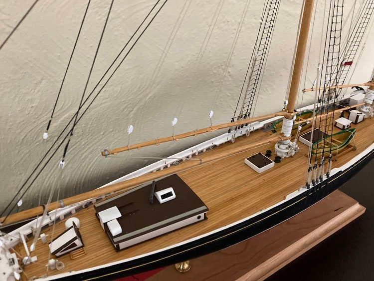
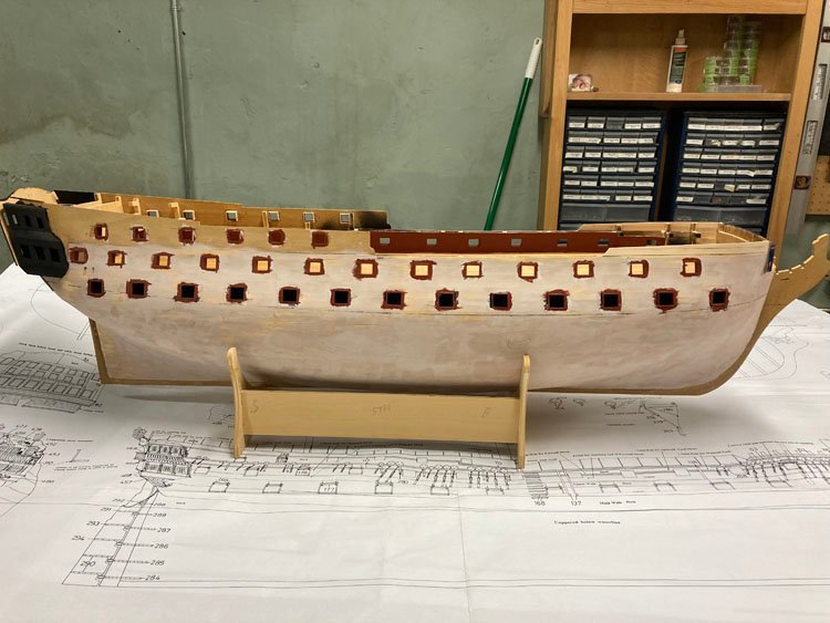
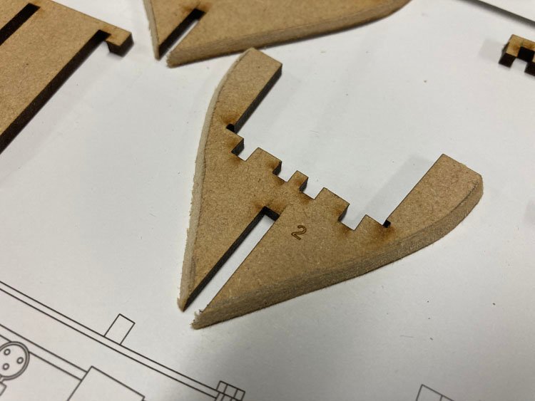
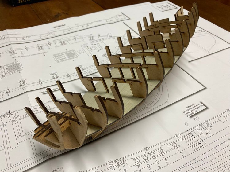
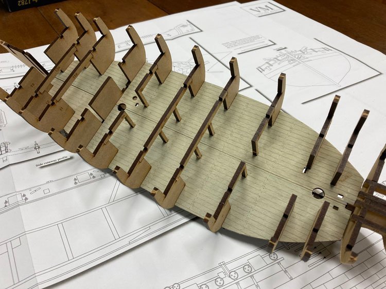
 Good Morning, It's been a while since I have been active in the forum, but that doesn't mean I haven't been active in my workshop. I have just finished my second Bluenose model, this one for my daughter. I didn't do a build log for it as it would be virtually identical to my first one. I ordered and receive the Speedy for my next project, but it no sooner arrived that I got a call from my near-by fellow ship modeller, Peter, who asked me if I would like to take on an Agamemnon. It had been his late father's who had started it, but been unable to finish it. Peter already had other things on his model-building plate, and since this particular type and era of vessel is not his chief area of interest, he thought it might appeal to me. He was right, however it is a pretty daunting project. The first planking is finished, the gunports are framed, the framework for the stern installed and the lower deck is planked. Everything to this point is beautifully done; I hope it isn't downhill from here. I will soon start a separate build log for this project. For the first time ever, I have two projects at once. I think I may work on them simultaneously. The idea of being able to move back and forth as the spirit moves me has some appeal. So with all that preamble over, here is my work on the Speedy so far. I have to admit that I am approaching this build log with a great deal of trepidation. There is some pretty impressive work out there and the bar has been set very high. I almost can't believe how precisely the parts have been cut - they fit together perfectly. I did a little pre-beveling on the first and last bulkheads. Notwithstanding the shiny bright finish on the deck of my Bluenose, for these naval vessels, I always prefer a grey finish. I've noticed that not too many others finish their decks that way, but I tend to like them. I wasn't sure how it would work on the etched deck of this model, but fortunately I was able to experiment on the lower deck which is almost completely unseen. I use artists' acrylic paint and make a very thin wash of gray, tempered with some yellow and/or brown. It worked quite well with this etched deck. The lines between the planks show up just the right amount. In a few spots the wash had overfilled the lines, so I ran a razor blade along them very lightly and it worked beautifully. I think I have just a bit too much yellow in my gray mix on this lower deck. For the upper deck, I'll make the colour just a bit grayer. It was great having this "practice" deck to work on. That's it for now. Thanks, David
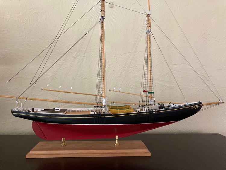
- 91 replies
-
- 15
-

-
- Speedy
- Vanguard Models
- (and 1 more)
-
Cheers from Port Hope, Ontario, Canada
David Lester replied to Peter Rumgay's topic in New member Introductions
Hey Peter. Welcome! It's great to have you aboard. Please share pictures of your models, I know everyone will love them. (Peter and I live only about five miles apart. I have seen his models and they are very impressive and quite unlike many of the others on this forum.) David -
Hi Derek, Glad to see you're back at your Bluenose. You mentioned that you're not a fan of painting, but you're right that it's pretty much essential for this hull. The white stripe that separates the red from the black is relatively easy to do. I just used 1/16" masking tape and it was straightforward. However the upper yellow stripe is actually quite tricky, but I think it's important to the look of the hull. If I'm not being too forward, I thought I would give you a heads up on it and how I approached the challenge.The problem is the fact that it goes immediately above the scuppers. There's plenty of room for it towards the bow, but towards the stern where the suppers are higher, there is very little room for it, and it can't spill onto the plank above as that plank is recessed. On the real vessel, the yellow stripe is actually a groove and it's very narrow. There just isn't enough room to create a neat and tidy groove especially in basswood, so it really needs to be applied to the surface. I'm currently building my second Bluenose model. I'm not doing a build log for the second one, as it would be a near carbon copy of the first, but I did handle the yellow stripe differently in each case and I think both results are acceptable. The first time around, I didn't have any really narrow masking tape, but I had a lot of Evergreen vinyl strips kicking around, so I painted one yellow and glued it on. It's very narrow and while it actually sits proud of the hull surface, it's so minimal that it's really undetectable. The vinyl strip is .01" x .03" and I think it's pretty close to the right width. This time around, I didn't have any vinyl strips of the right size, but I did find find 1mm Tamiya tape. It's just a bit wider than the .03" vinyl strip, but it seems to be acceptable too. I think anything wider than 1mm is going to be very difficult to fit on that plank and I think it will begin to look too wide relative to the real Bluenose. Overall, I'd say that the masking tape version is the easier one to do and probably the better solution, but at 1mm in width it just barely fits in. The other annoying problem is the colour of the tape which almost perfectly matches the yellow paint. It was hard knowing if I was placing the tape straight or wavy; there was almost no contrast. Anyway, not sure if that's at helpful to you or not, but I hope it's of some value. BTW I found the 1mm tape at Sunward Hobbies. I don't recall seeing it anywhere else. I'm enjoying your build log. David
-
Tom - sorry, I just came across your posts now. Not sure how I missed them. Thank you so much for your kind words. It seems to me that the blocks are an especially important feature on this model and I think an upgrade to Syren and BlueJacket is well worth it. Be sure to check out Tom Lauria on Youtube; he has some thoughts and tweaking the blocks which are interesting. Even if you don't do everything that Tom Lauria does, the BlueJacket ones will still need a bit of work in some cases. The beckets on the internally stropped blocks sometimes need drilling out, and they usually need a bit of filing, but they look and work great. I've built a number of models now and the CWM was my favourite one to do - it's challenging, but not frustrating because the kit is well designed and it goes together well. The detail is amazing and so far as I can tell, it's very accurate. At least it seems to match the pictures of the real vessel very closely. I'm sure you must be enjoying it too. Jared - thanks very much. I really appreciate it. David
-
Well, you're doing a lot better than I did. You're finding it simply the hardest kit you've ever built. I found it to be quite literally impossible! It's looking pretty good to me and congratulations on persevering. David
-
I'm not sure if others have gone through anything like this or not, but for some time now, I've been feeling very dissatisfied with my ship modelling. Although I have quite a few models under my belt, it seems that my skill level has not been improving and it was getting me down.... then I came across Derek's (Delf) build log for his Speedy and I have found just the inspiration I needed. I attribute my recent malaise to two things: the first has been laziness and not really paying attention to what I was doing, especially with rigging and seizing in particular. I was just quickly wrapping the seizing around the line in a haphazard manner, bunching it up against the block and then gluing it with too much glue. Then the block would often not hang naturally. Also, I could never get the thread ends cut close enough, so there were always two tiny tails sticking out from each one. Thanks to Derek, I can now see how with just a bit more care and attention, I can get beautiful seizings. And since, as we all know, the only thing that really separates any of us from true craftsmanship is another tool, I went on a shopping spree. I bought a pair of cuticle nippers, which are easily the very best tool for trimming the threads that I have come across, a Quadhands to replace the little so called "helping hand" (which was anything but) that I was using, some fly tying thread and as a special treat, a Serv-o-matic. I have been practicing tying seizings and am now getting results as good as Derek's. It's so energizing to find an area that I can improve significantly and doing so easily falls within my ability. My Serv-o-matic hasn't arrived yet, but I'm looking forward to using it too. I know I will never be a great hull planker. In fact, my skills in that department are closer to those of a drywaller than a modeller, (although I have never resorted to taping the joints,😄) and I'm just going to have to live with that. The second thing I needed to shake up was my model selections. I am quite fond of Model Shipways kits and have developed a comfort level with them. As a result, I have built them almost exclusively - in fact all of my models with the exception of one Mamoli have been MS. And my bad experience with the Ontario last year also made me more wary of other manufacturers. But I have been in rut. Most of the MS kits are built the same way and despite different subjects, it has felt like the same build over and over again. So, again thanks to Derek, as well as many other enthusiastic reviews, I have bought Vanguard's Speedy which arrived the other day and I am now eager to get going. I have spent some time on the plans and what a treat to have a rigging plan that can be deciphered and for which you don't need second sight to interpret. I have been trying to unload some of my finished models on family members. The only one my daughter would agree to take is my Bluenose, which unfortunately is the model I most want to keep. So I found myself agreeing to build a second one for her, which doesn't exactly address the problem I was trying to solve in the first place. Oh well. So I have it to finish up, then on to my Speedy. I'm very grateful for the inspiration I find at MSW! David
- 3 replies
-
- 21
-
-
Good Morning, You are not alone in finding this kit to be a real challenge. I'm sure by now you've seen my abortive build log and how I ended up abandoning this project. While I look forward to some challenge in every project, I found the tsunami of problems this one presented to be both perplexing and overwhelming. You've identified a few already. I don't mean to be too discouraging, but there are many more to come. It sounds as though you have some experience, so with any luck you'll be able to overcome the inherent problems. I sincerely wish you every success and I will be following with interest to see how you solve the various issues! All the best, David
-
Serving on Shrouds Question
David Lester replied to David Lester's topic in Masting, rigging and sails
Thanks for the feedback guys. I think I have a clear idea of how to proceed now. David -
I may be straining the premise that there is no such thing as a stupid question, but here goes anyway. I am thinking about "upping my game" by adding serving to the stays and shrouds on my next, but yet to be determined model. My question relates to seizing the shrouds at the mast top. It has always been my practice to double the shroud line over, place it in my helping hands and tie the seizing somewhere near, but not necessarily at the loop. Then place the loop over the mast top and slide the seizing up snug to the mast. I imagine that it would be all but impossible to slide the seizing over a served line. If I'm wrong on that notion and it is possible to slide the seizing, then I can't foresee an issue. However, if that is in fact the case, what is a good method to locate the seizing in exactly the right spot without sliding it? Would I place the loop over the mast top, perhaps clamp the lines together at a snug point, remove the clamped line from the mast and then add the seizing at the point where I placed the clamp? Or is there some other obvious approach that is staring me in the face and I just can't see it. Many thanks and all thoughts are most welcome. David
-
I am always leery of wooden belaying pins; in my experience they are almost always too heavy and in one of my models it wouldn't even have been possible to fit them all in, let alone have them look right. I tried some of the wooden pins that come from one of the Russian companies ( I don't recall which one.) They were exquisite - very fine but utterly useless. They were so fine that they couldn't withstand even the gentlest wrapping of the line around them. They just snapped off. So I have committed to using only brass pins. They at least approximate the right proportions and are reliably robust. I have noticed that pins on real ships often have a grayed out colour, so I always paint mine with Tamiya XF55 Deck Tan, which is a terrific beigey-gray colour. As for Cast Your Anchor, I believe they are still in business, but buying from them is not a great experience. You will get an automated response by email when you place the order, but you will never receive any further communication from them. They will charge your visa account the minute they receive the order and not wait until they ship it. You will never know when (or if) the order is shipped. If they do fill the order, it will take many weeks to arrive. I've only used them twice and I did ultimately receive the orders after several weeks, but I have heard of others who have not. If you email them, they will not respond and if you phone they don't answer the phone and you can't leave a message because the voice mailbox is always full. I would like to do business with them, as they seem to have a good inventory, and they're just a short distance away from me, but they're just so frustrating to deal with that I've given up. There are plenty of suppliers out there who are all great to deal with, so there's no need for an unpleasant experience. David
-
Hi Tom, Thank you very much for your kind words. In my opinion, the CWM is a superb kit and so far as I can tell, the plans are very accurate. It was my favourite kit to build. I'm sure you're going to enjoy it too. If you haven't already done so, be sure to look at www.charleswmorganmodel.com. If I remember right, the builder's name is John and he has shared dozens of pictures of the real CWM which are very helpful for clarifying details. And be sure to look at this article https://thenrg.org/resources/Documents/articles/BuildingGuidefForATryworks.pdf which is really a good one. I think it was the same writer who also had a great tip for building the seven whaling boats. The exteriors are easy to shape, but the interiors can be very difficult to do. The suggestion was to glue up the layers of the boats, then cut them in half lengthwise. It's then much easier to carve the interiors. When you've done that simply glue them back together and carry on shaping the exteriors and adding the finishing details. I love this solution because it is so counter-intuitive but it works like a charm. I have a few models under my belt now, but displaying them is getting to be quite a problem, so I'm trying to find homes for them. The CWM now lives at my son's house and my grandson now has my Rattlesnake displayed in his room along with his Lego collection. My last (completed) model was the Model Shipways Bluenose, which is another great kit and my daughter has expressed an interest in having it. The problem is, it's one that I really don't want to give up, so my next project will be a second one. I have ordered it and will be starting as soon as it arrives. It's a popular kit and is frequently out of stock at Model Expo, but I found one at Cornwall Model Boats. I can't believe that I will be building the same kit for a second time, but that's the way it's turning out. Thanks again, and best of luck with your CWM. David
-
Sad news - this is my last update for this model. I am afraid that I have abandoned this build. It may be my lack of skill, but I simply cannot make this kit come together. I know that Maris Stella has a good reputation so I don't want to be unfair. Perhaps a more skilled and more patient modeler than me could achieve success, but I have been having so much difficulty that it has ceased to be a pleasure for me. So, I've decided that life is too short and I'm letting it go. I put the guns and carriages together and gave them to my grandson, who is delighted with them - the most expensive set of toy cannons any five year old has ever received! I'm really sorry to post this, but I don't like unfinished build logs and I wanted to bring this one to a conclusion, even though it's not a very happy conclusion. Thanks very much for your 'likes' and interest in this build, and sorry to bring it to a premature end. David
-
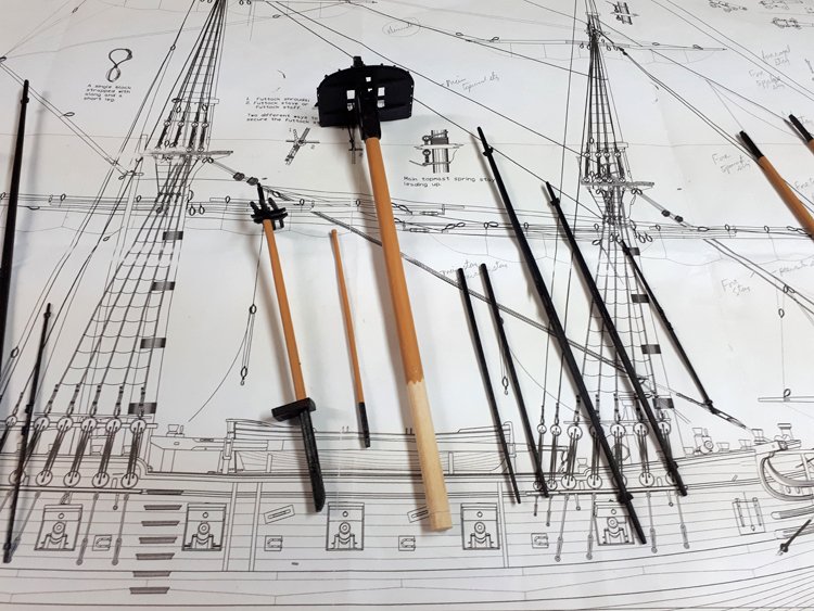
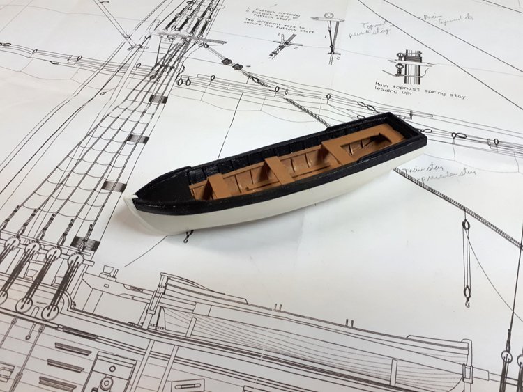
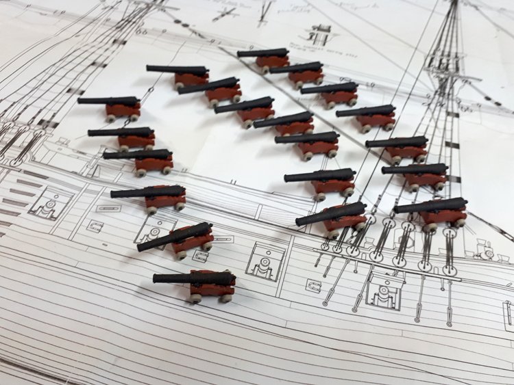
Good Morning Everyone and Happy Friday, 13th! A little update on my Ontario progress - I've been spending a lot of time on the stern and it's coming along quite nicely. I'll have some pictures in the next post. Concurrently, I've been working on some other bits and pieces. I've assembled the cannons and carriages and they have all come together very nicely without problems of any kind. In the past I have sometimes found the carriages a bit tricky, getting the cannon to sit a the right angle, etc, but I've had no trouble with these ones at all. There are two different sizes - 14 larger ones for the gun deck and six smaller ones for the upper deck. I finished off the boat, which I scratch built, basing it on the pinnace from my Constitution build, but detailing the interior for the Ontario. And lastly, I've made all the masts and yards. As you would expect, these were as straightforward as could be. No real need for much explanation. As is often typical, the mast tops and cheeks are provided. I wasn't sure what shade of yellow the stripe on the hull and the masts should be and I know from experience that no matter what shade I settled on myself, I would be convinced that there was another shade out there that would have been better and why the heck didn't I choose it instead. Since this is a British ship, I decided to order the admiralty paints that Caldercraft provides. So the masts and stripe are their "yellow ochre" and the gun carriages are their "red ochre." This way, I won't second guess myself. I wasn't as concerned about the black, but since I was placing an order anyway, I also got their "dull black" which you can also see. Next time, I'll have some pictures of the stern. Thanks again for your interest. David
-
Paul, I built the bulwarks in sections off the model as well. For some reason it seems to be a good method for this particular model. David
-
Don, It sounds like you got the same kit as I did, with the 3d stern pieces as standard and not any wooden ones. As I understand it, the kit is now produced with wooden parts for the transom and galleries as standard and the 3d parts are available to purchase separately. I don't know if the wooden parts are laser cut or to what degree the components have to be made, but I suspect at least part of them are laser cut, because Zoran told me that the photo etched windows will fit the wooden parts well, even though they don't fit the 3d parts very well. I'm not sure why the photo etched windows would ship with the 3d parts when they aren't a good fit. I tried to make them fit, but it was difficult to do because quite a bit had to be carved away from openings on the inside. The resin is quite brittle and fairly easy to break (especially the gallery pieces.) After Zoran suggested that I might be happier with scratch built windows, I tore them out and made new ones from my stash of 1/32 x 1/32 stock. They aren't quite as elegant as the photo etched ones, but at least they fit well. If you choose to use the 3d pieces, you'll be able to make them work ok, and when veneered with thin wood, they look quite good. It's just a bit tricky figuring out how to attach them to the hull. David
-
Thanks Bob! This was my favourite kit to do of all the ones I've done. I'm sure you'll enjoy doing it too. My CWM now resides at my son's house. Thanks again, David
-
Don, I meant to mention something for your benefit in my last post, but forgot to. If you are thinking about getting this kit in the near future, I believe that Zoran is now packaging it with wooden components for the transom and galleries, rather than the 3d printed ones, which will still be available for purchase separately if you thought you wanted them. However, as beautiful as the 3d printed ones are, I would stick with the wooden ones. Because the resin ones are rigid and can't be altered, they are very unforgiving. This means you have to build the hull to them, rather than the other way around. Normally if your hull varies slightly from the plans or (as if often the case with me) from side to side, you can accommodate it by adjusting the stern pieces slightly. This is not an option with the resin pieces. I know you have built a few Maris Stella kits before, so you might not find some of the things to be problems that I have. It might in part just be my unfamiliarity with their kits and plans. I have build MS kits almost exclusively, and as a result, my experience might not be as broad as it could be. There is a certain similarity to all kits produced by one manufacturer. I am really thankful that I have been in communication with Zoran, who takes such an interest. He has been a great help. I know this will be a nice model in the end. David
-
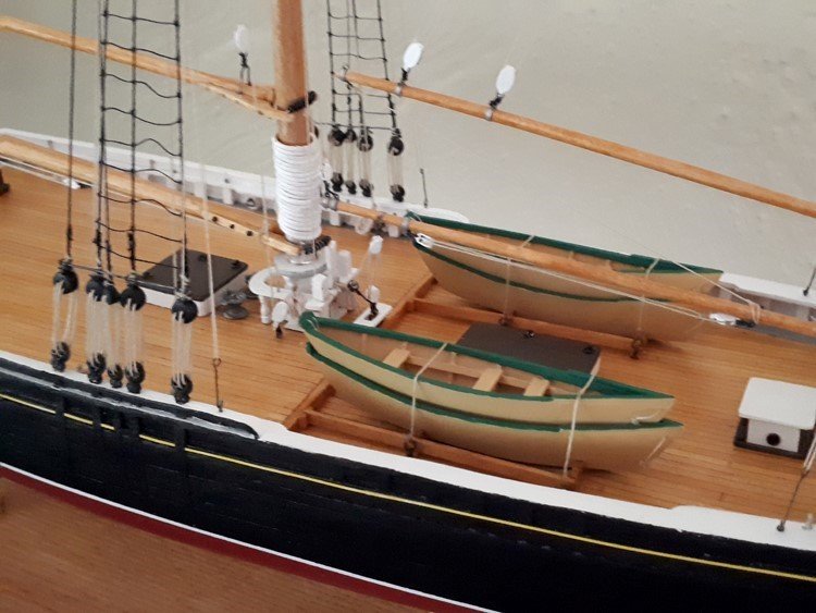
Hello Everyone, I have been working away on various elements of this build, but I've been a little bit all over the map, so I don't have too much that's too concrete to show. I've finished planking the hull and I'm happy enough with the result (remembering that I'm a "wood filler and paint" kind of builder.) I have been in regular communication with Zoran at Maris Stella and he has been very helpful with some of the problems I've encountered. I'm really appreciative of his interest and help. I hesitate to show you any further pictures as they show things in process and look pretty rough, but here goes nevertheless. The kit ships with exquisite photo etched windows, but I could not make them fit into the transom and gallery openings very well. Zoran indicated that they will fit more readily into the wooden pieces that now ship as standard with the kit, rather than the 3d printed pieces that I have. So I made new ones from stipwood. They aren't as elegant as the photo etched ones, but at least they fit the openings well. In addition I have veneered the window frames, which will look ok when all sanded and painted yellow ochre. (I realize that the windows need a bit more sanding/filing and at least one more coat of white paint.) When finished, these three pieces will be virtually entirely covered with wood and should look ok. I've also been working on the boat. The system that the kit comes with involves carving a form out of a block of balsa wood, attaching the keel, stern and stem posts, then planking it and finally removing the carved form. I found that I simply could not make this work at all and had decided to abandon the idea of a boat altogether when it occurred to me that it was almost exactly the same size as the boat on my Constitution. The two models are different scales, but the two boats are nearly identical in size and shape. The Constitution uses a method, that I think I've heard referred to as "bread board" and I have always found it easy to do. So I hauled out my old Constitution plans and build one from scratch. I glued up strips into boards and then cut out the six layers. I remembered a trick I read on this forum, (but forget just where) about how to carve out the interior of the boat. Once the layers are glued up, cut the boat in two lengthwise and shape the interior profiles separately. It's much easier to do in two pieces than in one. Then glue it back together and shape the exterior profile. I detailed the interior to match the Ontario rather than the Constitution and it's going to work just fine. I still have paint touch up and a bit more detailing to add. So that's where I'm at so far. It's been raining most of the week here, so little leaf raking has taken place, but it's supposed to be clear tomorrow and as they are almost knee deep already, I think I know what my Friday is looking like. David
.jpg.cd0a9bba1552aa7e21902d9867dfc294.jpg)
.jpg.677be71d2ff353e9be1d418336a1a329.jpg)
.jpg.958bf09b85fc7eba038a4c354fd6ed87.jpg)
.jpg.30eb6021a5df1a03905a5c3002a5f2dd.jpg)
.jpg.3e8022852de0443a80462a387cdefbad.jpg)
-
Rigging Question - HMS Ontario
David Lester replied to David Lester's topic in Masting, rigging and sails
That's great - it's perfectly clear to me now. Thanks, David -
Rigging Question - HMS Ontario
David Lester replied to David Lester's topic in Masting, rigging and sails
OK, I've got it now. Joe, your are right - they're the top gallant shrouds. It's just that the plans are so poorly drawn and components not identified that it's quite difficult to figure out what's what. You have to rely on your own knowledge and experience, (and of course, I seem to have to learn from scratch with each model! I even have to look up how to tie a clove hitch every time.) I may take your advice and substitute an eyebolt; I'll see how it goes when I get to that point. Allan - thank you - I'll check out Lees' Masting and Rigging. It may be well worth the investment. I have the Petersson and while it's quite clearly drawn, every time I refer to it, it seems to illustrate something that I already know and skips over exactly what it is I'm looking for. Many thanks, David -
Rigging Question - HMS Ontario
David Lester replied to David Lester's topic in Masting, rigging and sails
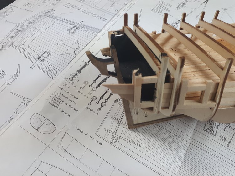
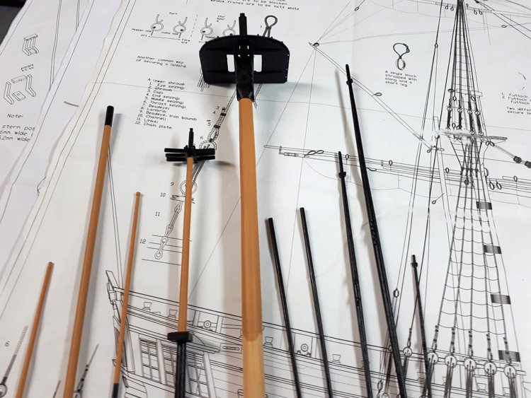
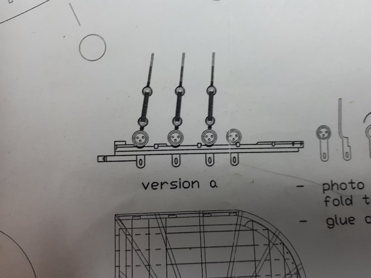
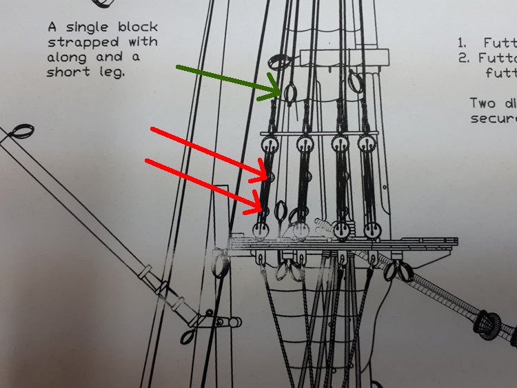
Hi Allan, The difference between "version a" and "version b" is simply the way the deadeyes are attached to the mast top. Version a uses the photo etched part shown just to the right. Version b (which isn't shown here) omits it and uses a piece of wire instead. Both versions show both the deadeyes in front and the bullseyes behind. The only thing I can think of, without really knowing, is that instead of the deadeyes being rigged in pairs, each is rigged individually, with the shroud running up from the deadeye, wrapped around the mast and down again to the bullseye behind. I don't know, I'm just guessing. In any case, I think I'll be leaving that detail off. Even if it is correct, I'm sure I would end up with a very cluttery mess if I include it. The rigging plans for this kit are so vague and unclear, and as I am beginning to suspect so incorrect that I'm going to have to ignore them almost completely and rely on other sources. For example, there isn't a single belaying point indicated anywhere on the plans and there are at least two too many stays shown between the main and fore masts and two or three too many between the fore mast and bowsprit. I can't even imagine what these stays would be. They don't even show how they're supposed to be attached. It's like someone just took a pencil and drew lines at random and it's quite a mess. I think I can find enough references for a brig rig to be accurate enough for my purposes (the only audience I have really is my wife and me,) but I don't know to what degree the fact that this is a snow brig changes things. Anyway, I'll continue to scour the internet to see what I can find. Any all input is welcome and appreciated. Many thanks, David -
Have you tried Modellers' Workshop in Montreal? (www.modellers-workshop.com)? They carry it. It's not clear from the website if it's in stock or not, but worth a shot if you haven't tried them already. David
-
I'm not anywhere near the rigging stage of my HMS Ontario, but I've been looking over the plans, trying to iron out the many, many questions that are arising. Here is the first of what I anticipate will be many. Maybe I'm revealing my ignorance by asking this, but I have not run across this before and I simply don't understand it. Here is the diagram of the lower deadeyes on the main mast top: It shows two bullseyes rigged together with the lower line appears to be wrapped underneath the deadeye. Here's the mast at the mast top: The deadeyes and shrouds appear to be rigged in the usual way. It also looks like the pair of bullseyes is behind the deadeyes, (red arrows) but I don't understand what they are, nor where the line they are securing originates. It would seem that the line marked with the green arrow is the right line, but if I follow it up it just disappears in an indecipherable mass of black lines where the shrouds converge. Do these lines wrap around the mast in the same way as the shrouds? I have never run across this before. Is this something unusual or am I just displaying my limited experience? In any case, I'm curious about what they are and how and where they originate. Can anyone shed any light? Many thanks, David
-
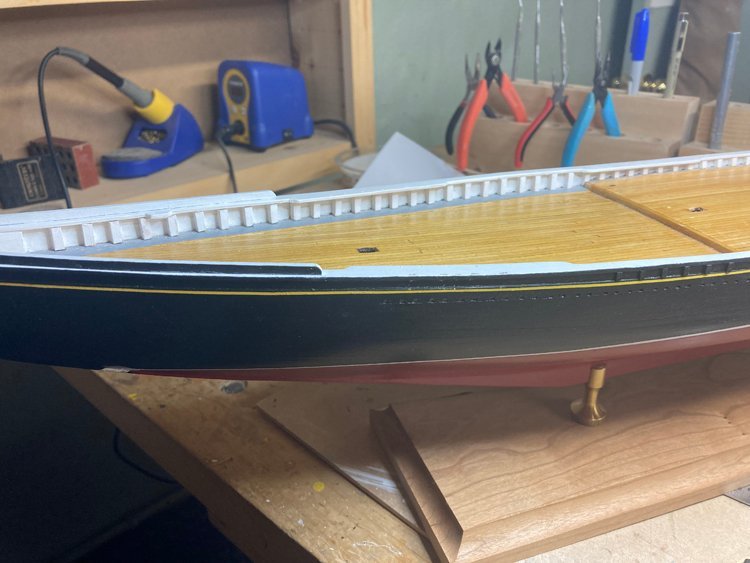
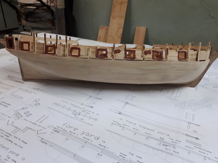
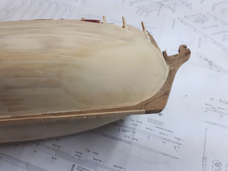
Good Morning, I now have the hull planked from the wales down. I'm afraid it's in my usual ham fisted style. Despite having build a number of models, I have never really gotten better at it. Oh well. If the hull is double planked, I don't really care too much about the look of my first layer. If the hull is single planked, I always have a decision to make as to whether I can live with the job I did or if I need to apply a thin second planking, which is what I did on my Pride of Baltimore. I used .5 mm strips for the second layer and the result was ok. I think I could have lived the results on this model if it were not for one problem. I think there is a design flaw in the profile of the hull at the bow. The prototype shows a nice rounded shape at the bow as you would expect, but on the kit, from about the third bulkhead forward and from about half way down the hull, the shape was actually concave! There was a huge indentation that was simply too great to ignore. At first I though I had done a poor job of fairing in this area, but I don't think that's the case because I did the minimum amount of fairing possible to achieve a smooth run, and I discovered that the problem was exactly the same on both sides. It seems that the second and third bulkheads are not nearly "full" enough and taper inward far too much. I "fixed" the problem with about a bucket of filler and was able to reshape the hull into an acceptable profile, but of course I now know I will be double planking. I've ordered some .5 x 5mm strips which will finish off the hull without adding too much bulk. I don't know about this kit - I know many people say great things about Maris Stella, but this one has been a struggle from the get-go. David
-
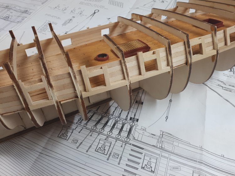
Good Morning Everyone, I'm working on the gun ports. I'm not sure if other kits work this way or not, but this kit suggests interior planking first, then attach the framing for the gun ports to the planking. This method is working extremely well. I used thicker framing than needed, so I could sand it down to the profile of the bulkheads. Despite my complaints about the plans not showing all the detail that I would like, I have to admit that where they are clear, they are very accurate. The measurements taken from the plans match my hull really well. There is also a number of sweep ports along each side. Since they will be closed, I'm not opening them up, but rather putting solid blocks in their locations, so I can interrupt the planking and attach the "door" easily. There's a nice piece of photo etched brass to use for the hardware on each one. I have decided not to finish most of the gun deck, as it will be invisible once the upper deck is in place. Because of that, and because the stern and gallery windows are so large, I decided to install a solid bulkhead near the stern, as well as "shadow boxes" at the gallery windows to create a cleaner look. My interior work in this area is a bit of a mess, so flat black paint is the obvious solution! I've taken a hard look at everything that is yet to come on this build and I believe that I now have all of the confounding issues behind me, (apart from the questions I still have on the rigging, but I'll cross that bridge when I get to it.) It appears that it will be straightforward from now on. Thanks again for checking in. David