


Thistle17
-
Posts
1,053 -
Joined
-
Last visited
Reputation Activity
-

 Thistle17 got a reaction from Saburo in HMS Winchelsea by cdrusn89 - FINISHED - 1/48th
I just tuned into your build and plan to add you to my list of member builds.
I don't revel in your problems.The transom is not an easy area to construct as many are finding out. Even the most experienced members have had either issues or have had cause to pause in that area. With those quarter galleys counting so much on transom correctness it separates this model from others such as Cheerful. I have been struggling with the transom on my build. Through some self inflicted wounds, problems related to doing enough homework, moving too fast and the like have me now in a transom restoration.
I find your methodology and process instructive. Thank you.
Joe
-
 Thistle17 got a reaction from FrankWouts in HMS Winchelsea 1764 by Thistle17 - 1:48
As I was preparing to build anew all the elements of the transom it struck me that I might try to salvage the transom that I had sawn off on my last attempt at assembly.
Since my transom angle was the driver for the removal it seemed to be a waste to just abandon it without trying a repair. I first trued up the cutoff ends of the port and starbaord C/D frames. Then I mortised into the cleaned up ends a deep enough mortise to give a tenon a substantial seat but not too deep as to protrude aft. Having saved scrap cedar from the kit I glued up "extenders of the same material thickness and let in the registration socket in each. One "extender" was cut to length (including the tenon length) for the starboard side. It was glued up using the cutout template for the element alignment. Since it had broken away from the transom full assembly it was easy to machine. The fuller assemblage was a bit awakward but it did fit my mill vice with some creative clamping. The port side extender will be cut to length and milled in a similar manner.
The mid transom frames would be more difficult to repair with them in an assembled manner so they will be treated differently. Since they require simple extenders I will "sister planks" of appropriate dimension to A and B frame ends. Having done so I will open up the respective bulkhead slots and reinstall the repaired transom. And this time I will use the template guide I fashioned.
Hopefully I will be back in business soon.
Joe
-
 Thistle17 got a reaction from glbarlow in HMS Winchelsea 1764 by Thistle17 - 1:48
As I was preparing to build anew all the elements of the transom it struck me that I might try to salvage the transom that I had sawn off on my last attempt at assembly.
Since my transom angle was the driver for the removal it seemed to be a waste to just abandon it without trying a repair. I first trued up the cutoff ends of the port and starbaord C/D frames. Then I mortised into the cleaned up ends a deep enough mortise to give a tenon a substantial seat but not too deep as to protrude aft. Having saved scrap cedar from the kit I glued up "extenders of the same material thickness and let in the registration socket in each. One "extender" was cut to length (including the tenon length) for the starboard side. It was glued up using the cutout template for the element alignment. Since it had broken away from the transom full assembly it was easy to machine. The fuller assemblage was a bit awakward but it did fit my mill vice with some creative clamping. The port side extender will be cut to length and milled in a similar manner.
The mid transom frames would be more difficult to repair with them in an assembled manner so they will be treated differently. Since they require simple extenders I will "sister planks" of appropriate dimension to A and B frame ends. Having done so I will open up the respective bulkhead slots and reinstall the repaired transom. And this time I will use the template guide I fashioned.
Hopefully I will be back in business soon.
Joe
-
 Thistle17 got a reaction from Edwardkenway in HMS Winchelsea 1764 by Thistle17 - 1:48
As I was preparing to build anew all the elements of the transom it struck me that I might try to salvage the transom that I had sawn off on my last attempt at assembly.
Since my transom angle was the driver for the removal it seemed to be a waste to just abandon it without trying a repair. I first trued up the cutoff ends of the port and starbaord C/D frames. Then I mortised into the cleaned up ends a deep enough mortise to give a tenon a substantial seat but not too deep as to protrude aft. Having saved scrap cedar from the kit I glued up "extenders of the same material thickness and let in the registration socket in each. One "extender" was cut to length (including the tenon length) for the starboard side. It was glued up using the cutout template for the element alignment. Since it had broken away from the transom full assembly it was easy to machine. The fuller assemblage was a bit awakward but it did fit my mill vice with some creative clamping. The port side extender will be cut to length and milled in a similar manner.
The mid transom frames would be more difficult to repair with them in an assembled manner so they will be treated differently. Since they require simple extenders I will "sister planks" of appropriate dimension to A and B frame ends. Having done so I will open up the respective bulkhead slots and reinstall the repaired transom. And this time I will use the template guide I fashioned.
Hopefully I will be back in business soon.
Joe
-
 Thistle17 got a reaction from gulfmedic1 in errors in blueprints
Dave we were given quite a revealing presentation about 2 years ago by a modeler who had developed a plan, defined the materials set and wrote the construction manual for a model available on the market today. The creator related that it was an iterative process in which he saw numerous deviations in many aspects of his design. A number of the deviations were with the manufacturing process i.e compromises in parts for whatever reason. He took much heat from the community at large for the deviations.
Why do I bring this up? Older kits and their drawings suffer some of the same ills, possibly more. Supposedly prestigious archival drawings and renditions in some repositories have been challenged by researchers. I came across this on my abandoned build of the Corel HMS Unicorn. When a design is reduced to a kit there are so many ways things can get out of wack that it isn't even worth listing them. Presently, I am working on a 1980's era model, a very expensive one, and I am finding drawing errors, omissions and the like.
We all have become more astute at this pass time and have imposed higher standards on what we accept as "bible". My advice to you is to establish a datum with the body plan. Let the given dimensional data guide you on what you pick as the reference. Have the drawing scaled to meet those dimensional requirements. Redraw/recreate the profiles to the correct scale if you need. Corel Draw is a handy way to get you there as you can scan in the profiles and manipulate them. Of course there is always the research avenue to aid you in resolution of inconsistencies. Perhaps the Peabody Museum may have some drawings you may avail yourself to as I see a reference on the drawing to East Boston.
Joe
-
Thistle17 got a reaction from FrankWouts in HMS Winchelsea 1764 by Thistle17 - 1:48
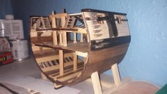
I managed to remove the sawn off frames and preserve the openings in the existing bulkheads. Of course there is residual PVA in the joints which will prevent good bonding of the new frames. I will attempt some remedy without opening up those frame slots. I had mentioned that I had two unused intermediate elements that were meant for the first go around. They are shown dry fit between #28 and #27 bulkheads. While they do not add much as fillers for strength they certainly will give some much needed unspoiled glue surface for the frames.
I am milling the boxwood for the frames and will be cutting them out shortly.
The saw in the foreground is the one I referenced earlier. It is such a great tool!
Joe
-
Thistle17 got a reaction from Edwardkenway in HMS Winchelsea 1764 by Thistle17 - 1:48
I managed to remove the sawn off frames and preserve the openings in the existing bulkheads. Of course there is residual PVA in the joints which will prevent good bonding of the new frames. I will attempt some remedy without opening up those frame slots. I had mentioned that I had two unused intermediate elements that were meant for the first go around. They are shown dry fit between #28 and #27 bulkheads. While they do not add much as fillers for strength they certainly will give some much needed unspoiled glue surface for the frames.
I am milling the boxwood for the frames and will be cutting them out shortly.
The saw in the foreground is the one I referenced earlier. It is such a great tool!
Joe
-
 Thistle17 got a reaction from JpR62 in HMS Winchelsea 1764 by Thistle17 - 1:48
I managed to remove the sawn off frames and preserve the openings in the existing bulkheads. Of course there is residual PVA in the joints which will prevent good bonding of the new frames. I will attempt some remedy without opening up those frame slots. I had mentioned that I had two unused intermediate elements that were meant for the first go around. They are shown dry fit between #28 and #27 bulkheads. While they do not add much as fillers for strength they certainly will give some much needed unspoiled glue surface for the frames.
I am milling the boxwood for the frames and will be cutting them out shortly.
The saw in the foreground is the one I referenced earlier. It is such a great tool!
Joe
-
Thistle17 got a reaction from FrankWouts in HMS Winchelsea 1764 by Thistle17 - 1:48
Glenn I am of your thinking. While I pondered the way out I cleared the slots in the existing framing. It took awhile so as not to destroy any semblence of alignment in the current bulkheads. I also had made some mahogany inserts, that I never used in the first go around, that fit exactlly between bulkheads #27 and #28. They could give me more glue area for the frames.
(As an aside I bought through Lee Valley their flushing cutting Japanese double edge pull saw. That has been a marvelous tool for getting fine accurate cuts such as these without wasting away material unneccessarily.)
Having reached this point I pulled out saved AYC plates, of chapter 1, that contained the frame elements. I am going to have a go at fashioning the stern frames from that blank. I have learned to hang onto any blanks for just such a use. I do not have AYC of that thickness but I do have box wood that can be used.
So, even without that margarita, thngs seem to be looking brighter at the moment.
Joe.
-
 Thistle17 got a reaction from Ryland Craze in HMS Winchelsea 1764 by Thistle17 - 1:48
I managed to remove the sawn off frames and preserve the openings in the existing bulkheads. Of course there is residual PVA in the joints which will prevent good bonding of the new frames. I will attempt some remedy without opening up those frame slots. I had mentioned that I had two unused intermediate elements that were meant for the first go around. They are shown dry fit between #28 and #27 bulkheads. While they do not add much as fillers for strength they certainly will give some much needed unspoiled glue surface for the frames.
I am milling the boxwood for the frames and will be cutting them out shortly.
The saw in the foreground is the one I referenced earlier. It is such a great tool!
Joe
-
Thistle17 got a reaction from FrankWouts in HMS Winchelsea 1764 by Thistle17 - 1:48
In the continued fairing process and double checking with template cutouts prior to port hole structural member installation I find I have yet another self inflicted "wound"! I thought I heeded the warning regarding getting the transom postioned correctly as a major factor to get the quarter galleys to come out correctly. But I found the transom angle incorrect after building the simple angle guage. I judged it was not "tweakable".
In thinking back I had used my adjustable digital angle guage prior and I can only speculate that the set angle changed from setup. To my dismay I found the transom angle too far off when compaerd to the guage shown. I can trace back some of the creep to my early attempts of fiddling with bulkhead #27 slot depth. It was not much but just enough to give me a cant too sharp to the vertical.
Progress came to a scheering halt last eve.
This morning I realized there was no opportunity to finesse the error. So off came the transom framing againt bulkhead #29! Now I am faced with the task of how I am to fix this problem. So with Jimmy Buffet's lyric ringing in my head ("Some people claim it's a woman to blame. But I know it's my own damn fault") I have looked at alternatives. None seem to pop at the moment.
1. Start all over again from the skeleton forward. Problem I see is that the framing kit is not even offered on the Syren web site at this time
2. Hat in hand go back and buy Chapter #1 kit for the 3rd time (I just sent it back and got a refund). It includes all the transom parts. How can I do that????
3. Remake bulkhead #27 through #29 and transom components by hand. Cut out those bulkheads and start again. All need to be cut extremely accurately and identically, especially in the slot areas.
So I will let this "cook" for a day or two and proceed.
Maybe after sipping a couple of those margaritas it will come to me.
Joe
-
Thistle17 got a reaction from Edwardkenway in HMS Winchelsea 1764 by Thistle17 - 1:48
In the continued fairing process and double checking with template cutouts prior to port hole structural member installation I find I have yet another self inflicted "wound"! I thought I heeded the warning regarding getting the transom postioned correctly as a major factor to get the quarter galleys to come out correctly. But I found the transom angle incorrect after building the simple angle guage. I judged it was not "tweakable".
In thinking back I had used my adjustable digital angle guage prior and I can only speculate that the set angle changed from setup. To my dismay I found the transom angle too far off when compaerd to the guage shown. I can trace back some of the creep to my early attempts of fiddling with bulkhead #27 slot depth. It was not much but just enough to give me a cant too sharp to the vertical.
Progress came to a scheering halt last eve.
This morning I realized there was no opportunity to finesse the error. So off came the transom framing againt bulkhead #29! Now I am faced with the task of how I am to fix this problem. So with Jimmy Buffet's lyric ringing in my head ("Some people claim it's a woman to blame. But I know it's my own damn fault") I have looked at alternatives. None seem to pop at the moment.
1. Start all over again from the skeleton forward. Problem I see is that the framing kit is not even offered on the Syren web site at this time
2. Hat in hand go back and buy Chapter #1 kit for the 3rd time (I just sent it back and got a refund). It includes all the transom parts. How can I do that????
3. Remake bulkhead #27 through #29 and transom components by hand. Cut out those bulkheads and start again. All need to be cut extremely accurately and identically, especially in the slot areas.
So I will let this "cook" for a day or two and proceed.
Maybe after sipping a couple of those margaritas it will come to me.
Joe
-
Thistle17 got a reaction from FrankWouts in HMS Winchelsea 1764 by Thistle17 - 1:48
If at first you fail to succeed try again...and again...and again!
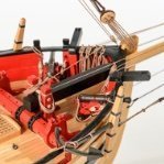
After 2 weeks of on again off again fiddling with the transom framing I think I finally arrived. In no small measure the suggestions and even the "boot in the tail" of the 'master' were the incentives to confront my impediments and move forward. As previously mentioned one key element was the replacement of bulkhead #29. I had adjusted the slots so much of the original ones that I lost the ability for the frames to stay put during construction. So I remade them out of some mahogany that I had gotten from a pattern maker. It took a bit of deliberate hand sawing to get them precise but in the end they proved to be the solution to the loose fit problem of the frames. From that point on it was just a matter of hand tuning the stern upper fillers to get the correct curvature of the stern.
In retrospect the 'boot in the tail' also got me to reflect on my state of mind during the prior attempts. As cautioned so many times before slow and steady is the ingredient needed on this model. But I might add one needs to have the right frame of mind and concentration is a must. I just didn't have it before. I was so frutrated about a week earlier that I even ordered the Chapter 1 kit again in anticipation of starting over. It turned out it was not needed.
While I am at it I would like to comment on the Syren kit. To have the kit manufacturer design, build and create instructions in a progressive manner is not to be taken for granted. When I finished the stern framing construction I pushed back and mused that Chuck must have had me in mind when he produced the kit parts for this section. Who else adds 'spare" parts and template guides as they perceive that some folk will have trouble in this section?
So in the end I think I am where I should be on the transom. I do have some upper counter tuning to do but for the most part it all works. The transom covering piece fits nearly perfect. For me the key was to concentrate on getting the stern port distancing precise.
Joe
-
 Thistle17 got a reaction from westwood in HMS Winchelsea 1764 by Thistle17 - 1:48
If at first you fail to succeed try again...and again...and again!
After 2 weeks of on again off again fiddling with the transom framing I think I finally arrived. In no small measure the suggestions and even the "boot in the tail" of the 'master' were the incentives to confront my impediments and move forward. As previously mentioned one key element was the replacement of bulkhead #29. I had adjusted the slots so much of the original ones that I lost the ability for the frames to stay put during construction. So I remade them out of some mahogany that I had gotten from a pattern maker. It took a bit of deliberate hand sawing to get them precise but in the end they proved to be the solution to the loose fit problem of the frames. From that point on it was just a matter of hand tuning the stern upper fillers to get the correct curvature of the stern.
In retrospect the 'boot in the tail' also got me to reflect on my state of mind during the prior attempts. As cautioned so many times before slow and steady is the ingredient needed on this model. But I might add one needs to have the right frame of mind and concentration is a must. I just didn't have it before. I was so frutrated about a week earlier that I even ordered the Chapter 1 kit again in anticipation of starting over. It turned out it was not needed.
While I am at it I would like to comment on the Syren kit. To have the kit manufacturer design, build and create instructions in a progressive manner is not to be taken for granted. When I finished the stern framing construction I pushed back and mused that Chuck must have had me in mind when he produced the kit parts for this section. Who else adds 'spare" parts and template guides as they perceive that some folk will have trouble in this section?
So in the end I think I am where I should be on the transom. I do have some upper counter tuning to do but for the most part it all works. The transom covering piece fits nearly perfect. For me the key was to concentrate on getting the stern port distancing precise.
Joe
-
.thumb.jpg.6d6ee4bdbfaac2c58ecc77e7b80ae374.jpg) Thistle17 got a reaction from Matt D in HMS Winchelsea 1764 by Thistle17 - 1:48
Thistle17 got a reaction from Matt D in HMS Winchelsea 1764 by Thistle17 - 1:48
If at first you fail to succeed try again...and again...and again!
After 2 weeks of on again off again fiddling with the transom framing I think I finally arrived. In no small measure the suggestions and even the "boot in the tail" of the 'master' were the incentives to confront my impediments and move forward. As previously mentioned one key element was the replacement of bulkhead #29. I had adjusted the slots so much of the original ones that I lost the ability for the frames to stay put during construction. So I remade them out of some mahogany that I had gotten from a pattern maker. It took a bit of deliberate hand sawing to get them precise but in the end they proved to be the solution to the loose fit problem of the frames. From that point on it was just a matter of hand tuning the stern upper fillers to get the correct curvature of the stern.
In retrospect the 'boot in the tail' also got me to reflect on my state of mind during the prior attempts. As cautioned so many times before slow and steady is the ingredient needed on this model. But I might add one needs to have the right frame of mind and concentration is a must. I just didn't have it before. I was so frutrated about a week earlier that I even ordered the Chapter 1 kit again in anticipation of starting over. It turned out it was not needed.
While I am at it I would like to comment on the Syren kit. To have the kit manufacturer design, build and create instructions in a progressive manner is not to be taken for granted. When I finished the stern framing construction I pushed back and mused that Chuck must have had me in mind when he produced the kit parts for this section. Who else adds 'spare" parts and template guides as they perceive that some folk will have trouble in this section?
So in the end I think I am where I should be on the transom. I do have some upper counter tuning to do but for the most part it all works. The transom covering piece fits nearly perfect. For me the key was to concentrate on getting the stern port distancing precise.
Joe
-
 Thistle17 got a reaction from scrubbyj427 in HMS Winchelsea 1764 by Thistle17 - 1:48
If at first you fail to succeed try again...and again...and again!
After 2 weeks of on again off again fiddling with the transom framing I think I finally arrived. In no small measure the suggestions and even the "boot in the tail" of the 'master' were the incentives to confront my impediments and move forward. As previously mentioned one key element was the replacement of bulkhead #29. I had adjusted the slots so much of the original ones that I lost the ability for the frames to stay put during construction. So I remade them out of some mahogany that I had gotten from a pattern maker. It took a bit of deliberate hand sawing to get them precise but in the end they proved to be the solution to the loose fit problem of the frames. From that point on it was just a matter of hand tuning the stern upper fillers to get the correct curvature of the stern.
In retrospect the 'boot in the tail' also got me to reflect on my state of mind during the prior attempts. As cautioned so many times before slow and steady is the ingredient needed on this model. But I might add one needs to have the right frame of mind and concentration is a must. I just didn't have it before. I was so frutrated about a week earlier that I even ordered the Chapter 1 kit again in anticipation of starting over. It turned out it was not needed.
While I am at it I would like to comment on the Syren kit. To have the kit manufacturer design, build and create instructions in a progressive manner is not to be taken for granted. When I finished the stern framing construction I pushed back and mused that Chuck must have had me in mind when he produced the kit parts for this section. Who else adds 'spare" parts and template guides as they perceive that some folk will have trouble in this section?
So in the end I think I am where I should be on the transom. I do have some upper counter tuning to do but for the most part it all works. The transom covering piece fits nearly perfect. For me the key was to concentrate on getting the stern port distancing precise.
Joe
-
Thistle17 got a reaction from Edwardkenway in HMS Winchelsea 1764 by Thistle17 - 1:48
If at first you fail to succeed try again...and again...and again!
After 2 weeks of on again off again fiddling with the transom framing I think I finally arrived. In no small measure the suggestions and even the "boot in the tail" of the 'master' were the incentives to confront my impediments and move forward. As previously mentioned one key element was the replacement of bulkhead #29. I had adjusted the slots so much of the original ones that I lost the ability for the frames to stay put during construction. So I remade them out of some mahogany that I had gotten from a pattern maker. It took a bit of deliberate hand sawing to get them precise but in the end they proved to be the solution to the loose fit problem of the frames. From that point on it was just a matter of hand tuning the stern upper fillers to get the correct curvature of the stern.
In retrospect the 'boot in the tail' also got me to reflect on my state of mind during the prior attempts. As cautioned so many times before slow and steady is the ingredient needed on this model. But I might add one needs to have the right frame of mind and concentration is a must. I just didn't have it before. I was so frutrated about a week earlier that I even ordered the Chapter 1 kit again in anticipation of starting over. It turned out it was not needed.
While I am at it I would like to comment on the Syren kit. To have the kit manufacturer design, build and create instructions in a progressive manner is not to be taken for granted. When I finished the stern framing construction I pushed back and mused that Chuck must have had me in mind when he produced the kit parts for this section. Who else adds 'spare" parts and template guides as they perceive that some folk will have trouble in this section?
So in the end I think I am where I should be on the transom. I do have some upper counter tuning to do but for the most part it all works. The transom covering piece fits nearly perfect. For me the key was to concentrate on getting the stern port distancing precise.
Joe
-
 Thistle17 got a reaction from Chuck in HMS Winchelsea 1764 by Thistle17 - 1:48
If at first you fail to succeed try again...and again...and again!
After 2 weeks of on again off again fiddling with the transom framing I think I finally arrived. In no small measure the suggestions and even the "boot in the tail" of the 'master' were the incentives to confront my impediments and move forward. As previously mentioned one key element was the replacement of bulkhead #29. I had adjusted the slots so much of the original ones that I lost the ability for the frames to stay put during construction. So I remade them out of some mahogany that I had gotten from a pattern maker. It took a bit of deliberate hand sawing to get them precise but in the end they proved to be the solution to the loose fit problem of the frames. From that point on it was just a matter of hand tuning the stern upper fillers to get the correct curvature of the stern.
In retrospect the 'boot in the tail' also got me to reflect on my state of mind during the prior attempts. As cautioned so many times before slow and steady is the ingredient needed on this model. But I might add one needs to have the right frame of mind and concentration is a must. I just didn't have it before. I was so frutrated about a week earlier that I even ordered the Chapter 1 kit again in anticipation of starting over. It turned out it was not needed.
While I am at it I would like to comment on the Syren kit. To have the kit manufacturer design, build and create instructions in a progressive manner is not to be taken for granted. When I finished the stern framing construction I pushed back and mused that Chuck must have had me in mind when he produced the kit parts for this section. Who else adds 'spare" parts and template guides as they perceive that some folk will have trouble in this section?
So in the end I think I am where I should be on the transom. I do have some upper counter tuning to do but for the most part it all works. The transom covering piece fits nearly perfect. For me the key was to concentrate on getting the stern port distancing precise.
Joe
-
 Thistle17 got a reaction from Rustyj in HMS Winchelsea 1764 by Thistle17 - 1:48
If at first you fail to succeed try again...and again...and again!
After 2 weeks of on again off again fiddling with the transom framing I think I finally arrived. In no small measure the suggestions and even the "boot in the tail" of the 'master' were the incentives to confront my impediments and move forward. As previously mentioned one key element was the replacement of bulkhead #29. I had adjusted the slots so much of the original ones that I lost the ability for the frames to stay put during construction. So I remade them out of some mahogany that I had gotten from a pattern maker. It took a bit of deliberate hand sawing to get them precise but in the end they proved to be the solution to the loose fit problem of the frames. From that point on it was just a matter of hand tuning the stern upper fillers to get the correct curvature of the stern.
In retrospect the 'boot in the tail' also got me to reflect on my state of mind during the prior attempts. As cautioned so many times before slow and steady is the ingredient needed on this model. But I might add one needs to have the right frame of mind and concentration is a must. I just didn't have it before. I was so frutrated about a week earlier that I even ordered the Chapter 1 kit again in anticipation of starting over. It turned out it was not needed.
While I am at it I would like to comment on the Syren kit. To have the kit manufacturer design, build and create instructions in a progressive manner is not to be taken for granted. When I finished the stern framing construction I pushed back and mused that Chuck must have had me in mind when he produced the kit parts for this section. Who else adds 'spare" parts and template guides as they perceive that some folk will have trouble in this section?
So in the end I think I am where I should be on the transom. I do have some upper counter tuning to do but for the most part it all works. The transom covering piece fits nearly perfect. For me the key was to concentrate on getting the stern port distancing precise.
Joe
-
 Thistle17 got a reaction from dvm27 in HMS Winchelsea 1764 by Thistle17 - 1:48
If at first you fail to succeed try again...and again...and again!
After 2 weeks of on again off again fiddling with the transom framing I think I finally arrived. In no small measure the suggestions and even the "boot in the tail" of the 'master' were the incentives to confront my impediments and move forward. As previously mentioned one key element was the replacement of bulkhead #29. I had adjusted the slots so much of the original ones that I lost the ability for the frames to stay put during construction. So I remade them out of some mahogany that I had gotten from a pattern maker. It took a bit of deliberate hand sawing to get them precise but in the end they proved to be the solution to the loose fit problem of the frames. From that point on it was just a matter of hand tuning the stern upper fillers to get the correct curvature of the stern.
In retrospect the 'boot in the tail' also got me to reflect on my state of mind during the prior attempts. As cautioned so many times before slow and steady is the ingredient needed on this model. But I might add one needs to have the right frame of mind and concentration is a must. I just didn't have it before. I was so frutrated about a week earlier that I even ordered the Chapter 1 kit again in anticipation of starting over. It turned out it was not needed.
While I am at it I would like to comment on the Syren kit. To have the kit manufacturer design, build and create instructions in a progressive manner is not to be taken for granted. When I finished the stern framing construction I pushed back and mused that Chuck must have had me in mind when he produced the kit parts for this section. Who else adds 'spare" parts and template guides as they perceive that some folk will have trouble in this section?
So in the end I think I am where I should be on the transom. I do have some upper counter tuning to do but for the most part it all works. The transom covering piece fits nearly perfect. For me the key was to concentrate on getting the stern port distancing precise.
Joe
-
 Thistle17 got a reaction from Trussben in HMS Winchelsea 1764 by Thistle17 - 1:48
If at first you fail to succeed try again...and again...and again!
After 2 weeks of on again off again fiddling with the transom framing I think I finally arrived. In no small measure the suggestions and even the "boot in the tail" of the 'master' were the incentives to confront my impediments and move forward. As previously mentioned one key element was the replacement of bulkhead #29. I had adjusted the slots so much of the original ones that I lost the ability for the frames to stay put during construction. So I remade them out of some mahogany that I had gotten from a pattern maker. It took a bit of deliberate hand sawing to get them precise but in the end they proved to be the solution to the loose fit problem of the frames. From that point on it was just a matter of hand tuning the stern upper fillers to get the correct curvature of the stern.
In retrospect the 'boot in the tail' also got me to reflect on my state of mind during the prior attempts. As cautioned so many times before slow and steady is the ingredient needed on this model. But I might add one needs to have the right frame of mind and concentration is a must. I just didn't have it before. I was so frutrated about a week earlier that I even ordered the Chapter 1 kit again in anticipation of starting over. It turned out it was not needed.
While I am at it I would like to comment on the Syren kit. To have the kit manufacturer design, build and create instructions in a progressive manner is not to be taken for granted. When I finished the stern framing construction I pushed back and mused that Chuck must have had me in mind when he produced the kit parts for this section. Who else adds 'spare" parts and template guides as they perceive that some folk will have trouble in this section?
So in the end I think I am where I should be on the transom. I do have some upper counter tuning to do but for the most part it all works. The transom covering piece fits nearly perfect. For me the key was to concentrate on getting the stern port distancing precise.
Joe
-
Thistle17 got a reaction from FrankWouts in HMS Winchelsea 1764 by Thistle17 - 1:48
Thanks Chuck. It seems to me I am loosing some concentration in addition to being too cautious and over thinking things as you say.
Believe me I am reading the monographs, especially yours.
I came back to the model after I'd walked away for an hour and figured it out. Of course when I trim (sand) back the 'C' frames they will give me the relief I need and when I bevel and fit the fillers all should come out well. I have come to be so sensitive to the fit of the elements since if not correct it will be a disaster with the construction of the quarter galleys.
What I ended up doing to get the transom frames to have the right fit and sit well was to remove bulkhead 29 and replace them with hand made new ones. That cured almost all the problems with frames "'A' and 'B' as they were too sloppy a fit with all my prior tunning.
Joe
-
Thistle17 got a reaction from glbarlow in HMS Winchelsea 1764 by Thistle17 - 1:48
Thanks Chuck. It seems to me I am loosing some concentration in addition to being too cautious and over thinking things as you say.
Believe me I am reading the monographs, especially yours.
I came back to the model after I'd walked away for an hour and figured it out. Of course when I trim (sand) back the 'C' frames they will give me the relief I need and when I bevel and fit the fillers all should come out well. I have come to be so sensitive to the fit of the elements since if not correct it will be a disaster with the construction of the quarter galleys.
What I ended up doing to get the transom frames to have the right fit and sit well was to remove bulkhead 29 and replace them with hand made new ones. That cured almost all the problems with frames "'A' and 'B' as they were too sloppy a fit with all my prior tunning.
Joe
-
Thistle17 got a reaction from Ryland Craze in HMS Winchelsea 1764 by Thistle17 - 1:48
Thanks Chuck. It seems to me I am loosing some concentration in addition to being too cautious and over thinking things as you say.
Believe me I am reading the monographs, especially yours.
I came back to the model after I'd walked away for an hour and figured it out. Of course when I trim (sand) back the 'C' frames they will give me the relief I need and when I bevel and fit the fillers all should come out well. I have come to be so sensitive to the fit of the elements since if not correct it will be a disaster with the construction of the quarter galleys.
What I ended up doing to get the transom frames to have the right fit and sit well was to remove bulkhead 29 and replace them with hand made new ones. That cured almost all the problems with frames "'A' and 'B' as they were too sloppy a fit with all my prior tunning.
Joe
-
 Thistle17 got a reaction from Dave_E in HMS Winchelsea 1764 by glbarlow - FINISHED - 1:48
One word describes your work....elegant!
Joe