


Thistle17
-
Posts
1,042 -
Joined
-
Last visited
Reputation Activity
-

 Thistle17 got a reaction from druxey in How to Make Mast Straps
I have used the pinstiping tape and it adheres quite well. However I am not aware that it can be found in flat sheen. If you locate such a product i would be interested to know.
I have used cresent paper with good success. Sharp cutting is required but it cuts well with little or no fuss. Gluing as you say can be problematical. I would think some diluted white glue painted on the back side might yield a good clean bond.
Joe
-
.thumb.jpg.6d6ee4bdbfaac2c58ecc77e7b80ae374.jpg) Thistle17 got a reaction from Matt D in Planking the Qdeck and Fcastle of your Winnie....planning ahead
Thistle17 got a reaction from Matt D in Planking the Qdeck and Fcastle of your Winnie....planning ahead
This is somewhat of a hybrid. featuring knees etc.
Joe
-
 Thistle17 got a reaction from mtaylor in Making frame drawings and its adoption to laser cutting
Kiyoo you are the consumate modeler, embracing modern technology, and maybe what is most remarkable is your willingness to share! i will send you a PM shortly.
Joe
-
Thistle17 got a reaction from druxey in Making frame drawings and its adoption to laser cutting
Kiyoo you are the consumate modeler, embracing modern technology, and maybe what is most remarkable is your willingness to share! i will send you a PM shortly.
Joe
-
Thistle17 got a reaction from mtaylor in Making frame drawings and its adoption to laser cutting
Kiyoo my experience with the results of the conversion (DXF to G code) taught me some lessons. For one, inside corners will always be rounded unlike laser processing. For outside corners the cutter has to go by the corner and return at the corner to have it come out square. As with laser machining there is always the feeds and speeds issue but the hardest lesson was that laser instructions seem to be much more forgiving in terms of path travel (we found arcs that were not continuous in the laser file that would not work in the CNC mode). Discontinuities in lines, arcs have to be "smoothed", nodes must be precise and so on. All in all i got my parts (for bulkheads and strongback) and they came out well. I believe you are absolutely correct that laser machining is the way to go. It would be the premier way if one could find a solution to char and the "slope" of the cut.
Joe
-
Thistle17 got a reaction from mtaylor in Making frame drawings and its adoption to laser cutting
Klyoo I have explored this arena (bringing today's technology to this pursuit, I worked with a colleague to convert laser DXF files to CNC G code, it was a real eye opener for me) but I pale in your light and work! Just outstanding. I await your completed treatment of the process but follow your good works.
Jooe
-
 Thistle17 got a reaction from CDR_Ret in Making frame drawings and its adoption to laser cutting
Klyoo I have explored this arena (bringing today's technology to this pursuit, I worked with a colleague to convert laser DXF files to CNC G code, it was a real eye opener for me) but I pale in your light and work! Just outstanding. I await your completed treatment of the process but follow your good works.
Jooe
-
Thistle17 got a reaction from mtaylor in Help planking around the keel
Hugo I assume you have used the planking tutorials on this web site, namely within the forum you have posted. So one has to ask have you created/added a simulated rabbett on the bulkhead strongback (center element that runs along the keel). Have you carved out the stern area of this element (deadwood in a real keel) so that your planks will lay down flush with a later added stren post? At times some slight tapering of these planks is acceptable to have them lay correctly in the stern area. Does this help?
Joe
-
 Thistle17 got a reaction from thibaultron in How to Make Mast Straps
I have used the pinstiping tape and it adheres quite well. However I am not aware that it can be found in flat sheen. If you locate such a product i would be interested to know.
I have used cresent paper with good success. Sharp cutting is required but it cuts well with little or no fuss. Gluing as you say can be problematical. I would think some diluted white glue painted on the back side might yield a good clean bond.
Joe
-

.thumb.jpeg.fc5d633a7b34428fcf19419a73d56d55.jpeg) Thistle17 got a reaction from EricWilliamMarshall in USF Essex by Thistle17 - Model Shipways - Scale: 5/32 - Kit bash
Thistle17 got a reaction from EricWilliamMarshall in USF Essex by Thistle17 - Model Shipways - Scale: 5/32 - Kit bash
And now we have Leo Goolden of Sampson Boat Company building/"restoring" Tally Ho to romance about. I watch 2 or 3 episodes a day and those of Acorn to Arrabella. There goes a couple hours when I could be focused on model building! Its hopeless.
Joe
-
Thistle17 got a reaction from mtaylor in How to Make Mast Straps
I have used the pinstiping tape and it adheres quite well. However I am not aware that it can be found in flat sheen. If you locate such a product i would be interested to know.
I have used cresent paper with good success. Sharp cutting is required but it cuts well with little or no fuss. Gluing as you say can be problematical. I would think some diluted white glue painted on the back side might yield a good clean bond.
Joe
-
 Thistle17 got a reaction from Bob Cleek in How to Make Mast Straps
I have used the pinstiping tape and it adheres quite well. However I am not aware that it can be found in flat sheen. If you locate such a product i would be interested to know.
I have used cresent paper with good success. Sharp cutting is required but it cuts well with little or no fuss. Gluing as you say can be problematical. I would think some diluted white glue painted on the back side might yield a good clean bond.
Joe
-
 Thistle17 got a reaction from Canute in How to Make Mast Straps
I have used the pinstiping tape and it adheres quite well. However I am not aware that it can be found in flat sheen. If you locate such a product i would be interested to know.
I have used cresent paper with good success. Sharp cutting is required but it cuts well with little or no fuss. Gluing as you say can be problematical. I would think some diluted white glue painted on the back side might yield a good clean bond.
Joe
-
 Thistle17 got a reaction from Roger Pellett in USF Essex by Thistle17 - Model Shipways - Scale: 5/32 - Kit bash
Eric i have put this model aside for the time being. I call it a bad habit of mine i.e. easily distracted. i went back to my Cheerful model and just dove in and got inexcorably hooked. In my younger days it was over a pretty girl. Guess old habits die hard. I can't believe it is almost 3 years ago that i started this posting.
i can't promise an immediate return but your query has given me a shove.
Joe
-
Thistle17 got a reaction from mtaylor in PBR Mark 1 River Patrol Boat by Thistle17 - FINISHED - Scale 1:6 - Model Shipwright Guild WNY
Amazing, just amazing! alross2 has sent us a response and access to the proper design drawings for the MK1 gun tub . The plot thickens a bit as he responds;
NAVORD 3741 attached. I'm wondering whether the boat at the museum has been monkeyed with, as I've never seen a MK56 mount on a MK1. The MK56 was fitted to the PBR MK2 and the PCF MK2, while both the MK1 versions used a modification of the WWII PT mount, the MK17. In the latter, the gunner was behind the weapons, as opposed to being between them in the MK56.
So we find some modifications may be in order. School is still out on this.
Thank you one and all!!!!
Joe
-
Thistle17 got a reaction from Canute in PBR Mark 1 River Patrol Boat by Thistle17 - FINISHED - Scale 1:6 - Model Shipwright Guild WNY
So revealing! Thank you.
Joe
-
Thistle17 got a reaction from Canute in PBR Mark 1 River Patrol Boat by Thistle17 - FINISHED - Scale 1:6 - Model Shipwright Guild WNY
I googled Browning 50 caliber machine guns and came across some videos that not only were impressive but made me pause as to how these guns, in a tub, functioned without burdening the user.
Joe
-
Thistle17 got a reaction from Canute in PBR Mark 1 River Patrol Boat by Thistle17 - FINISHED - Scale 1:6 - Model Shipwright Guild WNY
Thank you both for your comments. Blackreed your comments suggest familiarity with this type configuration. Although, Jim our modeler, is ex Navy, his duty was with nuclear power systems. That has left us with many questions of just how these weapons were loaded/reloaded, where the casings ended up and as you point out the spot light was just asking for it to be shot out.
-
 Thistle17 got a reaction from GrandpaPhil in PBR Mark 1 River Patrol Boat by Thistle17 - FINISHED - Scale 1:6 - Model Shipwright Guild WNY
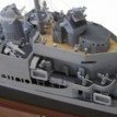
I know i have said this before but the gun tub is a project in itself making progress measured. Since the last posting, Jim, has made further advancement by assembly (albeit dry) of the gun carriage suspension components and has started some work of the gun locking system and other internal details. I think he is doing himself proud. Would you agree?
Please note the guns are not mounted in their respective carriages but lay along side for perspective.
Joe
-
Thistle17 got a reaction from mtaylor in PBR Mark 1 River Patrol Boat by Thistle17 - FINISHED - Scale 1:6 - Model Shipwright Guild WNY
So revealing! Thank you.
Joe
-
 Thistle17 got a reaction from alross2 in PBR Mark 1 River Patrol Boat by Thistle17 - FINISHED - Scale 1:6 - Model Shipwright Guild WNY
So revealing! Thank you.
Joe
-
Thistle17 got a reaction from mtaylor in PBR Mark 1 River Patrol Boat by Thistle17 - FINISHED - Scale 1:6 - Model Shipwright Guild WNY
I googled Browning 50 caliber machine guns and came across some videos that not only were impressive but made me pause as to how these guns, in a tub, functioned without burdening the user.
Joe
-
 Thistle17 got a reaction from Duanelaker in USF Essex by Thistle17 - Model Shipways - Scale: 5/32 - Kit bash
Ship board damage control now finds the bulkheads sanded fair at the keel rabbet and the rabbet strip and keel have been replaced.
Time to move on, by attending to the transom frames. These are very delicate members and have to be added somewhat "in the air" as they are attached, one by one to the former sides w/o much structural support. I will describe what I did but in hindsight I will also suggest an assembly method that might be a bit easier.
The pictures in Chapter 3 related to transom member assembly aren't too clear but they suffice. Once again I was on a roll with the bulkhead supports I had used for most of the other bulkheads and placed them (the vertical ones) on the aft end of #22. They should have gone on the inside of that bulkhead. This is going to give me a bit of the problem when I have to add the fillers where the stern terminates. However they did give a nice landing area for the inside stern frames that were to be added. I then added the 2 inner most stern members per directions (separated by 1/8 inch spacers along the former) to yield a 7/16" spacing. I liked the support they gave enough to add horizontal members port and starboard to support the remaining stern members. These are separated by 7/16" spacers per directions. All spacers and frame members are glued one to the other across the stern. These frames should be flush with the top of bulkhead #22.
I am left with the problem of still having to shape the stern with fillers as one does the bow. This I perceive will be a bit cumbersome. In hindsight I should have re-enforced the bulkhead from the inside as I said and executed the following:
On the aft side I would have placed a 3/8" X 1/2" strip across the bulkhead port and starboard side of the bulkhead and then filled in the balance of the stern area with balsa filler.
Also for the more fastidious modeler I would be tempted to extend the horizontal legs of each transom frame member such that they can extend forward of #22 bulkhead (slotting this bulkhead to accept the thicker base leg of the frames) and placing those 3/8" X 1/2" horizontal strips on bth sides of the bulkhead (i.e. forward and aft).
Joe
-
Thistle17 got a reaction from Duanelaker in USF Essex by Thistle17 - Model Shipways - Scale: 5/32 - Kit bash
This is a good news, bad news accounting.
The Strong museum demo/display was this past weekend. I used Essex for my demonstration for how a kit might begin and managed to assemble about 16 of the bulkheads before the end of the 2 day session. Today I installed the bulkheads 17 through 20. At this point one has to decide if the "strong back" stiffeners are to be added as they pass through bulkheads 3 through 20. They then are glued to the "strong back" and hopefully some of the bulkheads. It turns out this is a annoying task.. I say that because of slight irregularities in the slot of each bulkhead. Theoretically they all should line up and the stiffener just slides through, in this case from the stern, one to a side. If one uses the top of the strong back as the datum slight irregularities occur in the alignment of the slot from bulkhead to bulkhead. As it turned out I had to remove about 40 thousands from the stiffeners. and chamfer the edges to avoid any glue obstructions that may have occurred when the bulkheads were glued in place.
Stupidly I used CA to attempt to fasten the stiffeners to the strong back. I used the very thin CA and sure enough some trickled down onto my assembly jig gluing the keel to it!!!!! It took a bit of doing but I was able to extract the hull from the jig but in so doing the keel and most of the rabbet strip stayed behind. After a few moments of self chastisement I discovered it was somewhat of a blessing in disguise. I will have to make a new keel.
When using the top of the strong back as a datum and with each bulkhead set flush with it I observed that about 7 of the bulkheads protruded into the rabbet area. At this point I realized it was going to be a lot easier to sand the bulkheads at this point so there was no rabbet overlap prior to the keel repair! That's my good news. Sort of!
Joe
Note bulhead protrusion at rule 15 3/4 and 16 1/4.