
MORE HANDBOOKS ARE ON THEIR WAY! We will let you know when they get here.
×

CharlieZardoz
-
Posts
969 -
Joined
-
Last visited
Reputation Activity
-

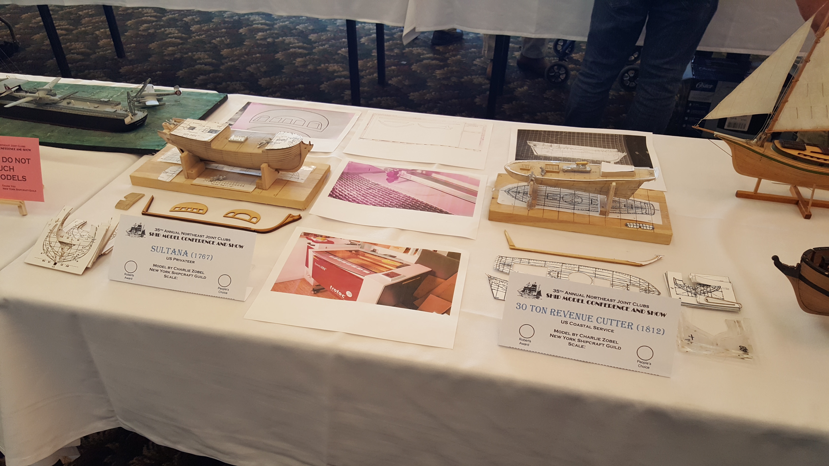
 CharlieZardoz got a reaction from VACorsair in 19th Century 31-ton Revenue Cutter by CharlieZardoz - Scale 1/64 - building as USRC Active based off Doughty plans and BlueJacket Shipcrafters kit
I also took the opportunity to resize some of the parts/plans from the kit itself. I literally just put the wood sheets into the scanner and then pushed the contrast waay up making the image black and white. I can then recut the parts using the laser at my workshop to the 1/64th size needed. In the future if I ever decide to resize another kit this will pretty much be the method to use, That said just a note regarding the kit templates, they weren't too bad but as you can see needed a bit of adjustment?
-
 CharlieZardoz got a reaction from archjofo in 19th Century 31-ton Revenue Cutter by CharlieZardoz - Scale 1/64 - building as USRC Active based off Doughty plans and BlueJacket Shipcrafters kit
The keel and hull lines are all separated same as I did with Sultana and templates cut out with carboard. I did this for both models. NOte my Sigmund Frued action figure to the left. he assures me that I am perfectly sane!
-
CharlieZardoz got a reaction from VACorsair in The subsciption frigate New York and other details
So first is what I believe to be the bone model of Chesapeake. Not sure why the stern differs a bit from the admiralty drawing though will assume it is meant to represent an earlier time nice detailing. The second is a Paul Garnett rendition of Philadelphia burning. I know there are a few models built of Philadelphia though haven't seen them in person but I assume the stern probably looks similar to this. You can see the false windows by the quarter galleries since she was destroyed before the fleet was modernized by 1812.
-
CharlieZardoz got a reaction from VACorsair in The subsciption frigate New York and other details
Two more examples of the seal around town...
This one is from the City Water Department at 179th And Amsterdam...a pretty sad seal. Not so ironically, it looks to have a lot of water stains.
But here's a gorgeous example..and the one other seal in public that has the year "1625." It's on 33rd Precinct at 170th and Amsterdam.
(added 3/6/2011)
Not a seal per se, but a sculpture that certainly picks up the theme--and was quite liberal with it, at 58 Bowery (1924, Clarence Brazer). Originally Citizen's Savings Bank, it's the HSBC at Canal and the Bowery, across from the entrance of the Manhattan Bridge. These guys are really taking a break--most significantly, they've swapped positions!
-
CharlieZardoz got a reaction from VACorsair in The subsciption frigate New York and other details
From the same source: "Here are some versions of the (pre-1977) seal on buildings throughout the city...
A High School on the CCNY campus uptown displays an accurate and faithful representation of the official seal in every detail.
This is the Landmark Preservation Commission's plaque on the Bowling Green fence.
The Louis Lefkowitz State Office Building, 80 Centre Street, 1930. The year 1664 is there, just very tiny.
99 Jane Street again. Because it was installed after 1977, the dateshould read 1625. Still, beautiful piece of work.
There are great examples of builders and sculptors taking liberties with the seal prior to 1915. In John Buckley Pine's account of the seal's history, he goes off on an entertaining riff about the vagaries the seal was subjected to. I considered inserting [Native American] for "Indian," but since it's already been noted... In woodcuts of the beaver these animals sometimes appear like dogs and sometimes like pigs with pointed snouts. The Indian is represented with a western war-bonnet on his head, or baldheaded....He shifts uneasily from the sinister side to the dexter side, and when he gets tired he sits down. The dexter supporter is equally unreliable in his conduct and more uncertain as to nationality and occupation.... He exchanges places with the Indian from time to time, strikes different aesthetic attitudes and keeps the Indian company in sitting down occasionally. He also keeps progress with the times in nautical science. He discards the old cross-staff [remember the cross-staff had vanished and so was not available to sculptors or builders!] and contents himself for a while with the lead-line....The eagle, too, is restless on his perch, as perhaps is to be expected of a liberty loving eagle. In 1784 he is rising to the dexter, as required by law, but in the 19th century he mounts in the other direction. Generally he looks where he is going, but occasionally he looks backward to see if he is being followed, as has been his habit of late years. Just after the Revolution, some flowers sprang up around the eagle, but with the increasing population of the City the opportunities for gardening have grown less and the flowers have disappeared, together with the old date 1686 which was retained for a while in the same seal.
And here are a few. If you know of others around town, let me know and I will add them!… 135 Charles Street, 1897. Le Gendarme apartments, the 9th police precinct until 1971. As they appear to lean on the shield, the sailor holds an oar and the eagle rises toward the center.
Soldiers' and Sailors' Monument, 1902. Perhaps because the monument was to recognize Civil War veterans, it would have been uncouth to spotlight a sailor from another era. Here, both "supports" definitely relax on the shield, and the dexter holds a shovel! The seal put to rest in 1915. The eagle looks again to the left, no cross-staff, and it's questionable whether the figure is a sailor at all.
226 West Broadway, formerly the Fire Department's High Pressure Services headquarter, 1918. Built during an apparent period of seal chaos, the sailor and Native American lean on the shield with a left facing eagle. Though the sailor's forearm is missing, you can see a plummet neatly wrapped in his floating fist. PS 3 on Grove Street in the Village. Though the school was definitely constructed after 1915, an explanation for the nonconformist seal might be found on the school’s own self-described history from their website: “The current PS 3, also known as the John Melser Charrette School, is very much a child of the 1960's, which is one reason you may occasionally hear it referred to as the 'hippie school.'” No cross-staff, leaning figures, eagle facing the wrong way. -
 CharlieZardoz got a reaction from Canute in The subsciption frigate New York and other details
Hi all! Been a bit I've been neck deep in my new business, I see this post has been evolving a bit. Interesting to think New York was salvageable by 1830. Regarding this "French style" was the Boston's stern also done this way? I say looking at Dan's version of the model on this site which also seems to have that central stack of flags type thing frolick described. What is the source of this info regarding New York's stern? Is it accessible somewhere?
-
 CharlieZardoz got a reaction from uss frolick in The subsciption frigate New York and other details
Hi all! Been a bit I've been neck deep in my new business, I see this post has been evolving a bit. Interesting to think New York was salvageable by 1830. Regarding this "French style" was the Boston's stern also done this way? I say looking at Dan's version of the model on this site which also seems to have that central stack of flags type thing frolick described. What is the source of this info regarding New York's stern? Is it accessible somewhere?
-
 CharlieZardoz reacted to Seahawk1313 in The subsciption frigate New York and other details
Hi Steve, Hal Bosche here, my models in your book, its been a long time. Interesting what you describe as in " French Style", I learn new things all the time, I always thought it referred the the shape of the Stern/ Taffrail. I'll have to rethink the New York when I "rebuild" it. I just don't like the City Seal, but that may be a part of carvings. My personnal feelings for the City getting in the way. The President carvings were very much in the "Wm. Rush" style. So much the learn and relearn, this is a great format. I wish there was something like this 20 -30 years ago.
-
CharlieZardoz reacted to Seahawk1313 in The subsciption frigate New York and other details
Just a History correction: The New York was NOT burned at Washington Navy Yard in 1814. Howard I. Chapelle was wrong. I have Bill Dune's notes; from (Taylor Peck, Round-Shot to Rockets, A History of the Washington Navy Yard and US. Naval Gun Factory, Annapolis: U.S. Naval Institute Press, 1949) . Also, 02-01- 1830, note on letter from William R. Nimmo of Baltimore to Secretary of the Navy John Branch inquiring about the possibility of salvaging the wrecks around Washington Navy Yard of which the New York was the only one visible above the water. If I can get Bill's note scanned and if anyone is interested I will add them. Basically New York was raised and surveyed in 1830 and found to be too expansive to do anything, was allowed to settle back into the Potomac mud. Bill was looking for more information as to what ever happened to it, but I don't know if he ever found anything more.
-
CharlieZardoz reacted to trippwj in List of "Sundries" for Frigate United States 1798
For those of you with curiosity concerning how the first US Frigates were equipped for sea, you may find a ten page listing of the sundries received by the Frigate United States in 1798 at the following link:
http://wardepartmentpapers.org/document.php?id=27521
There are some interesting items - including the quantity of powder (268 barrels), grape shot (3,705 2lb grape), compasses (several), 6 panes of glass, 99 gal sherry wine, 48 3/4 gal port wine, 62 gal molasses, and 462 gal of vinegar.
-
CharlieZardoz reacted to uss frolick in A first look at the Frigate John Adams, 1799-1829
Yea! Talos is back at his drafting table!
-
CharlieZardoz reacted to Seahawk1313 in The subsciption frigate New York and other details
Hello All, I built a model of the New York about 30 years age, not very good, needs a "Constellation" rebuild. I'll look for my papers and Bill Dune's notes to see what I used. I believe that the carving may have been done by Daniel N. Train, not sure if I found something or if it was something Bill thought. I also think the figurehead was Columbia, but don't think NYC seal type stern. If Train carved its stern I think it would be something like President's. Train was trained by Rush and had just gone out on his own. Very interesting topic . I am currently building Philadelpia, I built 5 stern windows but I'm changing it to 6. Wood cut "USS Philadelphia off Tetuan,Morocco" shows 6 windows.Photo Note:#NH65865-A, but don't remember where I found it, memory not what it was. P.S .I Built New York with 5 stern windows, but that was a guess, the stern was described as in the" French Style" in a news article, but nothing on the carving, stated they were impressive.
-
CharlieZardoz reacted to uss frolick in The subsciption frigate New York and other details
The "French Style" for that period generally means a central coat of arms, or stack of flags and cannon, with surrounded with heavy rope and vine tracery, and few, if any figures, unless they are a part of the coat of arms. President was definitely not in the French Style.
-
CharlieZardoz reacted to Beef Wellington in HMS Jason by Beef Wellington - Caldercraft - 1:64 - Artois-class frigate modified from HMS Diana 1794
Wow..Christian, Doug, Pat, Harvey, Carl, Tom, Wayne, VACorsair, Eamonn, and the likes, thanks guys for interest and the overly kind words. Narrative below will explain more, but think I've irrevocably stepped off the 'being happy with kit parts' ledge...this can only mean even slower progress...but perhaps more fun
I know I'm bouncing around a bit so apologies for that, but continuing foundational aspects which seem easier with the ship careened over on a towel.
Challenging Cheeks:
The kit supplied cheeks are hair rail are not that great. The cheeks themselves come nowhere near to fitting the hull, and I'm pretty sure the hull form is correct. The only option was to scratch my own cheeks. Aside from the fit, they are also seem rather undersized.
The next consideration was the hair rail and lower cheek, and decided to go whole hog and redo these as well. Given that there needs to be two of everything, I cheated and sparingly glued with PVA glue some 3mm sheet together and then cut to shape. The pieces were then separated using rubbing alcohol, and voila, 2 matching parts with the work of 1! These parts are still very slighty oversized to allow them to be fine tuned once other parts are made - necessary given I don't have any true plans to work from and that these pieces form quite a complex shape.
Photos below show hair rail prior to separation. The difference in dimensions is quite evident to that appearing in AOTS which I used as a guide for the scratch piece.
As a side note, the quality of the walnut parts are just not good, the main/false rail would need a lot a work to get presentable so suspect these will also be remade at some point.
The cheeks themselves took a long time (days) to get right due to the angled concave curve and lack of plans. Pretty happy with the results, though the parts still need some fine tuning as the rails are a little thick still I think. I'm hoping to use a scraper to give a profile to the edges, and a quick test shows that this should work OK even for a quick test. This also commits me to what will probably be my first simple carvings on the scrolls, but that's for another day.
Side by side comparison of scratch vs kit supplied pieces..
-
CharlieZardoz reacted to Cathead in USRC Ranger 1819 by Cathead – FINISHED – Corel – Scale 1:64
The foresail is made and rigged. This was essentially a repeat of the mainsail, so there's really nothing new to report. If you happen to notice that the fore- and mainmasts aren't at the same angle (spreading apart as they rise), that's a temporary mistake. I hadn't noticed it at first, but when I was experimenting with tightening down all the running rigging on the mainsail, I apparently overdid it and pulled the mainmast aft (no standing rigging is installed yet). It'll be fixed once I start installing more standing rigging.
Apologies for doing such a terrible job of updating this log. Among a variety of factors, I've been super-busy lately with my editing work over the last month, along with taking some online classes, meaning that sitting down on evenings or weekends to spend more time working with words on the computer for MSW hasn't really been high on my "fun" list. I also took a long-delayed trip to Kansas City, Missouri to revisit the Steamboat Arabia museum to research my next model project, another Missouri River steamboat along the same lines as my Bertrand but a sidewheeler from ten years earlier. I have a wealth of photos and measurements of the boat's salvaged equipment, stern, and cargo to pore over and write up, which has also been distracting me.
But I haven't given up on this ship! I'm also still working through my uncertainties about the standing rigging, and recently ordered some deadeye kits from Syren. Next up, I'll make and rig the remaining sails, then start in on the standing rigging. I hope to update again before another month goes past. Thank you all for sticking with me on this; it's nice to have even a small audience to keep me going as my brain wanders toward my beloved riverboats again.
-
CharlieZardoz reacted to Cathead in USRC Ranger 1819 by Cathead – FINISHED – Corel – Scale 1:64
After several weeks of work, the mainsail is rigged, and I have a confusing question about the standing rigging. First, the good stuff.
Here's how she looks overall. I'm quite happy with my paper sail-making methods; the color and texture really seem to fit into the all-wood appearance. All the running rigging for the mainsail is in place, though no knots are glued down yet. I want the option to tighten and adjust for a little while longer, so there are lots of loose ends and a few lines look baggy. As I intend to display the port side, I'm planning to have both the main and fore sails trimmed to starboard, with the forecourse and foretopsail (the two square sails on the foremast) trimmed to starboard as well, as if she were on a broad reach. Here's a few closeup photos:
I should have been taking progress photos this whole time, but haven't. I don't know if there's really anything to be learned from all this; the rigging is just a matter of thinking through steps carefully. The plans' rigging diagrams are good to follow once you understand their format, but their order of operations is terrible. Any given mast or sail's rigging is spread over multiple pages, and often something you'll want to do first is three pages later. I've spent so much time obsessively rereading the rigging plans to make sure I don't forget anything I'll regret later. So far, so good.
My plan is to continue working from the inside-out: make and rig the foresail next, then the standing rigging on both masts, then the forecourse and foretopsail.
Now for the question: looking ahead to the standing rigging, the plan of this model confuses me. It only calls for one lateral stay per mast, each leading down to a single set of deadeyes on a channel. Then there are two smaller lines that lead from the masthead, pass through the two arms of the crosstrees, and connect to blocks either on deck or on the channel. I can't understand this; here's a visual diagram that I hope makes sense:
In this rigging setup, there can be no ratlines because there's only one stay. How would sailors get up to the crosstrees to handle the upper sails, effect repairs, or do anything else? And what's the point of the other two lines, which aren't listed as stays but don't do anything else? I've looked at a variety of images and plans for topsail schooners like this, and most show two stays and deadeyes on the foremast with ratlines, but even they only show one stay and deadeyes on the mainmast, which I don't understand. And none show the other two random lines.
This is definitely an accurate rendition of the kit plans, but I don't understand how or why this would work in real life. I like to understand what I'm doing when I model, so I hope someone can either explain this to me, or offer advice for a more realistic setup. It seems to me that there should be two sets of deadeyes on each channel, with stays running up to the top of the lower mast at the crosstrees, so that each mast could have ratlines rigged. Anyone?
-
CharlieZardoz reacted to Chuck in USRC Ranger 1819 by Cathead – FINISHED – Corel – Scale 1:64
No I like to pop in and look at as many builds as possible when time permits. I might not say much but I enjoy watching everyones progress. You are doing a fine job.
-
CharlieZardoz reacted to Cathead in USRC Ranger 1819 by Cathead – FINISHED – Corel – Scale 1:64
Made some nice progress this weekend, lots of photos below.
Matt, thanks for the kind words! You probably actually think I'm nuts for sticking with the kit materials, but it's an interesting challenge to my way of thinking. Plus, I don't have anywhere near the metal-working skills you do (yes, I know there's only one way to change that). It's too late on the rings, I already glued them in, so we'll just see how that goes. Also, I did use Cog's advice and knotted some small strips beneath the channel blocks; seems to have worked nicely.
Building the cabin, you guessed it, involved overcoming flaws in the kit. First, the kit only provides fore and aft bulkheads to build the cabin around, with only very thin planking to wall it in. That seemed like a bad idea to me. So I added longitudinal bulkheads to provide a solid surface all the way round.
The same problem exists for the roof, which again they expect you to plank in with no support. Uh uh. So I added some roof braces.
Of course, the height of the shoulders on the kit-original bulkheads didn't match, so that the fore bulkhead was higher than the after bulkhead. So I sanded a camber into the fore bulkhead to accomodate this, figuring it was probably a realistic choice anyway. I also started adding windows and planking.
After some trial and error I got the whole cabin built and planked. So little extra wood is given in this kit that I literally finished this with nothing to spare. I couldn't have afforded to break one single piece. I think it came out nicely, although one part of the roof planking is slightly cockeyed. It's only visible to the camera lens under harsh light, though. I like how the color balance came out, I wanted to cabin darker than the deck so it would stand out.
Now for another kit problem. The pre-cast mounting ring for the carronade has two pegs underneath that are meant for holes in the deck. No problem, right? After all, those holes are pre-drilled in the plywood underdeck, so all you have to do is plank over them, file them open, and mount the ring. Yeah, no. I didn't think to pre-test the fit of the ring until now, and sure enough one of the holes was way off. One hole was right where it should be to mount the ring dead-center on the deck; the other was over a diameter too far outboard. I had to measure and drill a new mounting hole. Below left, you see the ring mounted properly, with the original factory-drilled hole in its horribly visible location. Below right, you see how I decided to handle this: I just filed a couple of wood scraps to look like some kind of step or brace against the ring. They'll vanish into the clutter of the deck once the model is complete, and only a serious naval historian would wonder what the heck they're for (and that person would already realize that this model is not museum-quality).
Finally, I mounted the rudder. More CA glue leaked around the edges of the iron bands than I would have liked, under the right light there's some annoying glistening along the edges. But under most conditions it's not noticeable and I think the rudder looks nice overall. I also mounted the tiller. The kit-drilled tiller hole didn't come close to matching up with the angle of the rudder, so I just cut off the rudder post and shaped a new tiller post that I glued to the top of the deck instead. No one will ever now but you, gentle readers.
I have to say, it's been really fun adding all the deck detail, this thing is starting to feel like a real ship build. I hadn't intended it to turn out as it has so far, but now I'm liking the shades of bare wood and the simple black iron fittings. I've given up on trying to match this to any specific plans or ship, it's evolved to just become a fun personal model. Thanks for reading.
-
CharlieZardoz reacted to Cathead in USRC Ranger 1819 by Cathead – FINISHED – Corel – Scale 1:64
I've been working on rigging the first blocks to the deck fittings; I decided it would be better overall to do this before installing the rings. It's been easy to hold each ring in a clamp, tie the block on & glue it in place, then insert the ring into the deck. This way if I make a mistake it isn't already attached to the model. Below are the first six block/ring assemblies in place around the foremast's hole. These will be in tension vertically once rigged, so I don't care how they lay about for now.
I also assembled and installed the channels, which led to an unresolved problem. Each channel has a regular deadeye attached to a chainplate, then a block that's supposed to be tied to the channel. See below.
The problem is, the instructions just say to tie this block to the channel, and show what looks like some kind of small stopper knot beneath that would hold the block in place. But the hole in the channel is way too large for this; the size knot it would take to keep this block in place under tension would be almost as big as the block itself, and would look ridiculous.
So my problem is, how do I fix this block in place? Do I somehow tie a small scrap of wood onto the line to act as a stopper? Do I try to CA the line to the underside of the channel? I've been having trouble searching for an answer to this on MSW and elsewhere, as the search terms are so vague. Any ideas?
-
CharlieZardoz reacted to Cathead in USRC Ranger 1819 by Cathead – FINISHED – Corel – Scale 1:64
I have been working on the deck fittings.Below, you see the deck with all holes drilled for the metal fittings (rings, bits, etc.):
And here you see most of the fittings test-placed (unglued) to get a sense of the deck's layout. Many of these will have small blocks; I'm trying to decide whether I should tie those in before gluing down the fittings, or afterward.
Another source of annoyance in this kit: these metal fittings have "pins" meant to fit into the deck holes, but many of them are too thick or long. For example, the stanchions which will hold safety lines have pins nearly the width of the rails, as shown in the blurry photo below. I've drilled smaller pilots holes, but am reluctant to drill any wider for fear of splitting the rail. So I may have to file down all these tiny parts to fit proper holes.
I've also had this problem with the plates and other hull fittings; their pins are so long that holes drilled in the rails would go right through. As it is, I've been desperately careful drilling pilot holes sideways through these rails without poking through. So I've been spending lots of time filing down the pins on these fittings to be narrower and pointier so I can drive them into the wood and have them hold more securely.
It's been very fiddly work but I think it'll come out ok. As this is the first rigged ship I've ever attempted, I don't know if this kind of thing or normal, or unique to the Corel kit.
Are there any thoughts on whether to pre-rig blocks to the rings, or do it after gluing the rings in? Anything else I should be considering at this stage?
-
CharlieZardoz reacted to Barbossa in HMS Diana By Barbossa - Caldercraft - Scale 1:64 - The 1794 Attempt
Here's part II
Last pic is dedicated to 1) MSW Staff : congrats regarding the software update and Ray : consulting his buildlog (HMS Diana fvinished +/- a year ago) made things more easier and comprehensable., Cheers Ray
-
CharlieZardoz reacted to Barbossa in HMS Diana By Barbossa - Caldercraft - Scale 1:64 - The 1794 Attempt
Here's part 2
As mentioned in previous post, the model has no crowsfeet, but it's a nice detail and I like the contrast between the black masttops and the light color of the thread.
-
CharlieZardoz reacted to Barbossa in HMS Diana By Barbossa - Caldercraft - Scale 1:64 - The 1794 Attempt
Crowsfeet ? I love them
For the interested : the euphroe-blocks are made of styrene. Walnut was not an option
I fixed 2 small sheets of 0,5 mmm and one of 0.25 mm in the middle : thas was (more or less) the suitable thickness.
A needle and a pin to obtain the best possible alignment to fore the 0.8 mm holes
The paint is from the Acrylico Vallejo-brand and the 311 colortype is until now the closest to wood, at least in my opinion, some more filing before assembly and that was that.
Here's the pics (part I)
-
CharlieZardoz reacted to mtaylor in Licorne 1755 by mtaylor - 3/16" scale - French Frigate - from Hahn plans - Version 2.0 - TERMINATED
Thanks for the commets, the likes, and the ideas.
After some thought, it's now deconstruction and construction time. I figure if I'm not going to do it right, then don't do it at all. In the first picture, you can see where I'm ripping up the deck back aways. There's also the most inboard strake laying on the beams forward. I'll redraw, re-cut, and install one strake at a time on each side and follow Gerard's drawing and attempt the "random" bits as to plank length. I think this will be the best way and definitely interesting from my point of view.
Just for kicks and grins, here's the laser cutting those first planks.
Feel free, as always, to jump in and point out errors or misconceptions. This is a journey...
-
CharlieZardoz reacted to mtaylor in Licorne 1755 by mtaylor - 3/16" scale - French Frigate - from Hahn plans - Version 2.0 - TERMINATED
"Well... this is a fine mess I've gotten myself into, Ollie..... " -Stan Laurel
I finally got the pictures off the camera, sized. These are as she sits right now and for the last 2 days. The information from Gerard gives me pause and some deep thought. Right now, I'm wondering if I can "fix" this such that the planking butts are random without causing undo harm to the beams, my sanity, etc.
The catch is the quarterdeck ends just after the main mast. I could random butt joint from here forward as the butt joints where the cannon and mastershipwright are would not be seen from above but the ones at the main mast area will be visible. Forward, the butt joints show up well before the forecastle so they'd be out in the open also. There are ladders, ship's boats, and cannon in the open area between quarter and foredeck but not enough "things" to hide the joints.
I'm going to think this through and fiddle with the drawings and if I think I can pull this off (maybe strip back some of the planks) and make it "random" I will. i'll try to salvage as much of the planks as I can since I already have the rest of the gundeck planks cut and hate the idea of tossing them all out. If I can't.... I'll just have to go with what I have.
Any thoughts, advice, etc. will be considered and appreciated.
Anyway... pictures. The dummy cannon is being used to see if there's any problem with gunports and decking. So far, so good, or so I thought.