


ccoyle
-
Posts
8,762 -
Joined
-
Last visited
Reputation Activity
-

 ccoyle reacted to Panagiotis in Kilkis ex Mississippi (BB-23) by Panagiotis - FINISHED - scale 1:100 - Greek Battle Ship
Hi all.
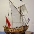
After the construction of the model of Armed Cruiser Averof and a time of laziness, I decided to start a new model. This time it’s the Battle Ship “Kilkis”, another warship of the Greek Navy.
Kilkis (Greek: Κιλκίς) was a 13,000 ton Mississippi-class battleship originally built by the US Navy in 1904–1908. As “Mississippi bb-23” she was purchased by the Greek Navy in 1914, along with her sister “Idaho bb-24” and they both renamed as “Kilkis”, and “Lemnos”.
Kilkis was named for the Battle of Kilkis-Lahanas, (an aria nearby the town of “Kilkis” at northern Greece) a crucial engagement of the Second Balkan War.
She was armed with a main battery of four 12 in (305 mm) guns, Kilkis and it was the most powerful vessel in the Greek fleet. (along with her sister “Lemnos”)
The ship saw limited action during World War I. as it was decided to be operated solely as a harbor defense ship.
In the immediately ensuing Greco-Turkish War of 1919–1922, “Kilkis” supported the Greek landing in Asia Minor and participated in the final Greek sea-borne withdrawal in 1922.
She remained in service into the early 1930s, when she was used for a training ship. During the German invasion of Greece in 1941, she and her sister were sunk in Salamis by German Ju 87 Stuka dive-bombers. The two ships were ultimately raised in the 1950s and broken up for scrap.
More of its history http://en.wikipedia.org/wiki/Greek_battleship_Kilkis
Below I post some photos of her Greek carrier.
Thanks
.........................
.........................
.........................
.........................
....................................
-
.thumb.jpeg.fc5d633a7b34428fcf19419a73d56d55.jpeg) ccoyle got a reaction from EricWilliamMarshall in Part VI: Building V108 - The Superstructure
ccoyle got a reaction from EricWilliamMarshall in Part VI: Building V108 - The Superstructure
No we'll add some aft superstructure parts. As a rule of thumb, we'll work from forward aft, and we'll avoid adding tall, spindly structures, such as the galley stack (61), until later.
First we'll add the two galley skylights aft of the radio room, parts 35.
These consist of two frames and two skylights. Score, cut, color, and fold the frames; CA is a good choice for tacking the frame edges where they close together. Add the skylights and glue the finished assemblies down on the locator-numbered squares. The skylights slope down towards their outboard edges.
Next we come to the two stacks, the forward stack (27) and the aft stack (28).
The two stacks are almost identical, so I'll describe the construction of the forward stack, and the construction of the aft stack is basically a repeat.
Cut out the parts for the forward stack, parts 27a-27d. There's a misnumbered part in the sequence -- the long, white strip should be 27e. Color the edge of 27a, being careful not to color the portion alongside the white stripe. Next, roll the stack. Remember to lightly moisten the back of the part. Part 27b is a joiner strip; use the 20# bond version of this part. Apply glue to one-half of 27b and glue that half inside one or the other side of 27a.
Apply glue to the other half of 27b and close the stack cylinder. Use tweezers to reach inside the cylinder and pinch the seam tightly shut. The two edges of the seam really need to butt tightly together, or fit problems with 27d may result.
Somewhere in your stash of leftover parts you should have parts 27c and 28c. These are formers for inside the stack cylinders. The diagrams say nothing about where inside the cylinder these should go, so I guessed at it. You can't seat them too low, or the stacks won't fit over the hull profile formers, and you don't want them too high up, otherwise your stack will look like it has a flat cap. I seated my formers about 1/4" down the stack cylinders. Once you get 27c seated, you'll need to paint the inside of the stack black.
Part 27d is a flange that goes around the lower stack. Cut, color, and roll the flange. This is another conical part, and rolling it with a conical object against a soft surface works well.
On this particular tiny ring, using the glue tab is helpful, and the overlap at the tab won't be terribly conspicuous. When the ring is glued closed, carefully work the ring over the lower stack until it is lined up on the dashed locator line, then apply a small amount of glue to the underside of the flange where it meets the stack. Make sure to line the seam of the flange on the seam of the stack, because both the flange and stack have centerline marks to help line up the stacks on the superstructure. When the flange is done, the forward stack gets a doubled stripe (27e).
The stacks have locator marks for optional rungs. Again, I used some from a photo-etch fret. There are also locator marks for optional guy wires, which I will not be adding (partly because there are no locator marks for the wires on the deck).
The finished stacks fit snugly over the hull profile former. Apply a small amount of glue to the edges of the profile former, then slide the stacks into place, using the centerline marks to get the front and rear edges lined up properly. The ladder rungs should be just off to the starboard side of center.
-
ccoyle reacted to ianmajor in Part VI: Building V108 - The Superstructure
Chris,
Fabulous work. I have to keep reminding myself how small the scale is!
-
 ccoyle got a reaction from trippwj in Poorly designed ship model kits or those that are plain made-up (edited by admin)
The title of this thread has been edited. Please read the first post here on title etiquette.
With regards to the subject, fictitious kit subject histories, I think this is something of little concern to the manufacturers. Bottom line: as long as the kit sells, what motivation do they have to make sure it's historically accurate? Sad, but true.
-
ccoyle got a reaction from EricWilliamMarshall in Part VI: Building V108 - The Superstructure
Time to add the bridge wing details. These include the navigation light, parts 25d and 25e, and several gratings, parts 29 and 30.
The navigation light housings present a minor decision - there are two ways to fold them, and either way you have to color the reverse side. So, I will use these to introduce yet another new technique. So far, all the fold scoring we have done is for parts that fold down, but what do you do if you have a part that needs to fold up? After all, there are no fold lines printed on the reverse of the part. It seems like the direction of the fold shouldn't matter, but it does - scored lines definitely want to fold one way more so than the other. When you fold up from a scored line, a tiny pucker is created along the folded seam; 99% of the time this pucker might not make a difference, but for really tiny parts, that pucker might result in not being able to place another part correctly.
So, here's how to score the reverse of a part, using a navigation light housing (25dL) as an example. Make a small cut right at the end of and exactly in line with each of the printed fold lines, like so:
Flip the part over - now the cuts act as two points to define a line. Connect the points with your scoring tool (I used the cutting technique on these because of their size) and you're ready to proceed.
Now, if you use this technique, 25dL actually becomes 25dR and vice versa -- doesn't really matter which one is which as long as you get the orientation of the housing correct on the bridge wing, along with the proper color of light. Finishing the navigation lights requires folding up and gluing the two sides of the housing, coloring the reverse side, and adding the light lens (25e). Use the 20# bond version of the lenses, if you have them, or delaminate the card versions for easier forming. Here's a finished light:
Next we need a few gratings, parts 29 and 30. These are pretty straightforward - score, cut, color, fold, done. Part 30 goes abaft the wheel, while parts 29 and the navigation lights go on the bridge wings - there are locator marks for all of these. Make sure the port light is red and the starboard is green. If you're doing the modified railings, make sure you don't glue these parts right on the edges of the bridge wings - you need a little room to install the railings.
-
 ccoyle got a reaction from ianmajor in Part VI: Building V108 - The Superstructure
I thought about using PVA glue, but I wasn't sure if it would dry hard enough. I applied the top coat from the inside mainly because a) the applicator brush was too large to keep everything entirely within the frames, and b ) I didn't want to see what would happen if I tried to wipe off any excess on the printed side of the part. As with any medium, there's usually more than one way to do these various tasks with card, so thanks for sharing alternative methods.
With regards to very small parts, especially these detail parts that are many times smaller than a fingertip, it pays to handle them as much as possible with tools, such as tweezers, instead of fingers. I even use my knife tip for picking up small parts from my cutting mat - a light stab to pick up the part doesn't leave a visible mark on the printed surface.
Cheers!
-
ccoyle reacted to ianmajor in Part VI: Building V108 - The Superstructure
Chris,
Great stuff. I am impressed by the way you handle the small parts. Whenever I have made card models I always seemed to get the detail parts stuck to my fingers or tools rather than the model.
I have used Crystal Clear successfully. With practice I found you can apply it from the outside of the widow frame without affecting the surrounding area. Useful for repairing damaged windows on nearly or completed models.
This came from the model aircraft guys who I believe originally used nothing more exciting than diluted PVA glue for glazing small windows.
-
ccoyle got a reaction from EricWilliamMarshall in Part VI: Building V108 - The Superstructure
Next up is the engine room telegraph, consisting of the base (31a), mounting bracket (31b), telegraph (31c), and telegraph handle (31d).
The base, 31a, presents a new challenge, since it is a tiny cone, not a tiny cylinder. Rolling a cone is much easier if you have something conical to form it with. The tip of my scribing tool is perfect for this job.
In all other respects, rolling a cone is the same as rolling a cylinder. The mounting bracket has fold lines; on such a small part, the usual scoring and folding process doesn't work very well. I recommend using your knife tip to cut through the top layer of paper fibers only, then complete the bends. The two parts 31c go back-to-back to make the telegraph; when this is done, glue the telegraph into its bracket. The handle, 31d, also has fold lines, but don't bother with them. Glue one side of the handle to one side of the telegraph, then bend the handle over to the other side of the telegraph and attach it. Dab a little glue to the inside of the handle and then crimp it closed with tweezers. Personally, I think the handle should be wood, so I painted it brown. Glue the finished telegraph to its base and glue the base to the proper spot on the bridge.
Last up is the ship's wheel. Cut, roll, and glue the stand (32a) in the same manner as for the compass stand. The wheel housing (32b) is a tiny box; give its fold lines the knife-tip treatment, then fold up and glue the sides. Attach the housing to the stand. The wheel spokes (32c) and ring (32d) require some careful cutting. Remember to cut away from the wheel hub. Cut the inside of 32d first, then cut the ring from the parts sheet; glue the ring to the spokes, then glue the completed wheel to the housing. Don't worry about edge coloring parts 32 b-d before gluing - the finished wheel and housing can be painted brown once everything is glued together. Glue the finished wheel assembly to the bridge deck.
Now we can add the bridge roof (26a and 26b) and radio room (26c).
The radio room has printed windows, but there are no parts for detailing the radio room interior, so we're going to let the windows be. There's a spot on the radio room wall to add a hatch (part 55 - hinges to the left). Use contact cement to glue the roof (26a) and roof interior (26b) together. Score, cut, and fold the radio room (26c) and attach it to the roof one wall at a time. There will be a gap in the aft wall where it meets the foremast.
The roof/radio room assembly can then be mated to the bridge assembly. Afterwards, you can add the two pices of entryway fascia port and starboard (these were originally part of 25c if you did the modified construction; they'll still be attached if you've used the unmodified 25c). Not-quite-finished bridge should so far look like this:
Now, sit back and admire your work for a bit. Next we'll add the bridge wing details.
-
ccoyle got a reaction from EricWilliamMarshall in Part VI: Building V108 - The Superstructure
At this point, if you set the bridge assembly atop the conning tower, you'll notice that the radio room floor partially covers the locator for the foremast (the red spot).
We'll need to fix this before going further. Either carefully cut or drill out the foremast step on the conning tower roof, along with the corresponding bit of the radio room floor (the aft end of the bridge deck).
We'll also take a few moments to apply the edging to the bridge deck wings. This edging is the bottom part of the portions of part 25c we removed earlier (if you're not modifying 25c, you'll just be attaching the entire part 25c to the bridge deck; however, take note that the red portions of 25c - where the navigation lights will be placed - should be removed before gluing 25c to the bridge deck). Remove this bottom edge of the part 25c wings and glue these, one section at a time, to the bridge wings.
We're going to do some things out of sequence again. Following the parts numbers sequence would require us to add the radio room and bridge roof at this point, followed by the stacks, but that would make it difficult to get at the bridge interior, so we're going to add the interior details first. These will be some very tiny assemblies, but fear not! Tiny card assemblies require some care, some special techniques, and some tools, but they're not especially harder than larger assemblies. The interior parts are parts 31-33.
We'll start at the bridge wall and work aft (makes sense, doesn't it?), so the first assembly will be the compass, parts 33a (stand) and 33b (compass rose - albeit sans printed rose!). Part 33a needs to be rolled into a very small diameter tube. This presents a number of difficulties. First, very narrow tubes are almost impossible to roll from regular card stock, so in this case it will be easier to roll the part printed on 20# bond (remember waaaay back when I suggested you print the parts on both card and regular paper?). The second difficulty is the joiner tab; it will create an overlapping seam and isn't really necessary. You can remove the tab and close the tube by running a narrow bead of CA along the seam and squeezing the tube closed.
OK, so here's another stupid warts story. In this next picture, I'm rolling the 20# bond version of 33a around some styrene rod. What you can't see is that I moistened part 33a with my tongue - but the part stuck to my tongue and got too wet. It subsequently got all smooshed during the rolling process.
I destroyed the part! What do I do!? Fortunately, this little disaster presents the perfect opportunity to introduce a second way of dealing with part 33a! You see, card stock is made of multiple layers of paper fibers, and it is possible to separate the layers. I used the tip of my #11 blade and gently teased apart the paper layers at one corner of the card stock version of part 33a.
Once I have enough of the exposed layers to grab onto, I can then gently peel the two layers apart, and voila! I now have the equivalent of a 20# bond part. Now, it so happens that this particular tube I'm rolling has the same inside diameter as the styrene rod I'm rolling it with. So, for this tube, I'm going to actually wrap and glue the printed part to the styrene rod, then trim the rod to match the length of the tube. This makes a much sturdier base for the compass. Finishing the compass is a simple matter of cutting out and edge coloring the compass rose, gluing it to the stand, and gluing the finished compass to its spot on the bridge floor.
-
ccoyle got a reaction from EricWilliamMarshall in Part VI: Building V108 - The Superstructure
OK, now it's on to the bridge! This will be an interesting part of the build, because it has numerous tiny parts and also presents a number of options for improving the model.
We start with parts 25a (top of bridge deck) and 25b (bottom of bridge deck). Glue these together with some contact cement.
Notice that on the bottom of the bridge deck, there are three very small white spots; these are locator marks for the bridge deck supports to be added later. To make these marks more functional, we need to drill them out a bit. I use a small finger drill I made by gluing a #73 wire-sized drill bit into a short section of bamboo skewer. Drill carefully so as not to drill all the way through the card - we want just a shallow socket (drilling 25b before gluing the two parts together would avoid this difficulty).
Next we'll add the bridge wall, part 25c. The back of this part needs to be colored, so before removing it from the sheet, I gave the reverse side a coat of gray primer (you can see the scored fold lines through the paint).
At this point, you need to decide if you want to use the basic part as-is, or make some modifications. These are completely optional, so don't feel any pressure to add them - it's supposed to be fun after all. The first option I will show you is glazing the bridge windows. First you'll need to very carefully remove the printed windows. Remember to cut away from the corners! Also, note that there is some subtle, printed shading on the windows - there's the obvious, light-gray portion of the frame, but there's also a far less obvious, dark gray portion of the frame that is almost identical in color to the 'glass' portion of the window. Take care to remove only the glass areas, or the frames will be unnecessarily thin and delicate (they'll be delicate enough already!). The insides of the frames need to be colored. The space is too cramped for a marker, so I colored these with acrylic paint - the bottle says "Japanese Navy Gray", but I've modified the color at least once in the past, so I don't know what shade it is now.
The next option to decide on is whether to use the printed bridge railings or not. If you study the part carefully, you'll see that the railings are actually meant to portray railings covered by storm canvas. You can either go with the printed railing, or you can choose to replace them with either bare railings or more realistic storm canvas railings. I'll be adding scratch-built storm canvas railings; that being the case, the next step is to remove the railings portion of 25c (but don't discard them - we'll need part of them later). Skip this step if you use the printed railings. I'm also removing the side entrance fascias at this point, since it will be easier to add them later as separate pieces.
The bridge wall needs to be formed before glazing the windows, else we'll damage the glazing. Here I'm rolling the bridge wall over the handle of my hobby knife.
Now, what to use for glazing? There are numerous materials that can be used for glazing. In the past, I have used microscope slide slip covers (great material, but stiff and therefore ill-suited for curved surfaces), clear report covers (flexible, but don't glue well), window envelope panels (crinkle easily), and clear acetate overhead projector sheets (flexible, but don't like to hold a curve). Microscale makes a glue called Crystal Clear that dries clear and can be used for glazing small windows like these, but I don't have any. I'm a big advocate of the card modeling philosophy of "use whatever you can find around the house", and in this case what I found was my teenage daughter's top coat nail polish.
This I worked into each window until a film filled the entire window space. The top coat dries fairly quickly. It doesn't dry perfectly clear, but it does dry clear enough to suggest real windows are there, and that's the effect we want. Here's the finished windows:
Notice there's top coat residue around the windows - this is why the clear coat is applied only from the inside of the bridge wall. Once it dries, the area around the windows can be touched-up with paint. The finished bridge wall is glued to the bridge deck with contact cement, although I had to tack the outermost corners with a spot of CA to get them to stick tightly.
Next: adding interior bridge details.
-
 ccoyle got a reaction from catopower in Part VI: Building V108 - The Superstructure
OK, now it's on to the bridge! This will be an interesting part of the build, because it has numerous tiny parts and also presents a number of options for improving the model.
We start with parts 25a (top of bridge deck) and 25b (bottom of bridge deck). Glue these together with some contact cement.
Notice that on the bottom of the bridge deck, there are three very small white spots; these are locator marks for the bridge deck supports to be added later. To make these marks more functional, we need to drill them out a bit. I use a small finger drill I made by gluing a #73 wire-sized drill bit into a short section of bamboo skewer. Drill carefully so as not to drill all the way through the card - we want just a shallow socket (drilling 25b before gluing the two parts together would avoid this difficulty).
Next we'll add the bridge wall, part 25c. The back of this part needs to be colored, so before removing it from the sheet, I gave the reverse side a coat of gray primer (you can see the scored fold lines through the paint).
At this point, you need to decide if you want to use the basic part as-is, or make some modifications. These are completely optional, so don't feel any pressure to add them - it's supposed to be fun after all. The first option I will show you is glazing the bridge windows. First you'll need to very carefully remove the printed windows. Remember to cut away from the corners! Also, note that there is some subtle, printed shading on the windows - there's the obvious, light-gray portion of the frame, but there's also a far less obvious, dark gray portion of the frame that is almost identical in color to the 'glass' portion of the window. Take care to remove only the glass areas, or the frames will be unnecessarily thin and delicate (they'll be delicate enough already!). The insides of the frames need to be colored. The space is too cramped for a marker, so I colored these with acrylic paint - the bottle says "Japanese Navy Gray", but I've modified the color at least once in the past, so I don't know what shade it is now.
The next option to decide on is whether to use the printed bridge railings or not. If you study the part carefully, you'll see that the railings are actually meant to portray railings covered by storm canvas. You can either go with the printed railing, or you can choose to replace them with either bare railings or more realistic storm canvas railings. I'll be adding scratch-built storm canvas railings; that being the case, the next step is to remove the railings portion of 25c (but don't discard them - we'll need part of them later). Skip this step if you use the printed railings. I'm also removing the side entrance fascias at this point, since it will be easier to add them later as separate pieces.
The bridge wall needs to be formed before glazing the windows, else we'll damage the glazing. Here I'm rolling the bridge wall over the handle of my hobby knife.
Now, what to use for glazing? There are numerous materials that can be used for glazing. In the past, I have used microscope slide slip covers (great material, but stiff and therefore ill-suited for curved surfaces), clear report covers (flexible, but don't glue well), window envelope panels (crinkle easily), and clear acetate overhead projector sheets (flexible, but don't like to hold a curve). Microscale makes a glue called Crystal Clear that dries clear and can be used for glazing small windows like these, but I don't have any. I'm a big advocate of the card modeling philosophy of "use whatever you can find around the house", and in this case what I found was my teenage daughter's top coat nail polish.
This I worked into each window until a film filled the entire window space. The top coat dries fairly quickly. It doesn't dry perfectly clear, but it does dry clear enough to suggest real windows are there, and that's the effect we want. Here's the finished windows:
Notice there's top coat residue around the windows - this is why the clear coat is applied only from the inside of the bridge wall. Once it dries, the area around the windows can be touched-up with paint. The finished bridge wall is glued to the bridge deck with contact cement, although I had to tack the outermost corners with a spot of CA to get them to stick tightly.
Next: adding interior bridge details.
-
ccoyle got a reaction from ianmajor in Part VI: Building V108 - The Superstructure
At this point, if you set the bridge assembly atop the conning tower, you'll notice that the radio room floor partially covers the locator for the foremast (the red spot).
We'll need to fix this before going further. Either carefully cut or drill out the foremast step on the conning tower roof, along with the corresponding bit of the radio room floor (the aft end of the bridge deck).
We'll also take a few moments to apply the edging to the bridge deck wings. This edging is the bottom part of the portions of part 25c we removed earlier (if you're not modifying 25c, you'll just be attaching the entire part 25c to the bridge deck; however, take note that the red portions of 25c - where the navigation lights will be placed - should be removed before gluing 25c to the bridge deck). Remove this bottom edge of the part 25c wings and glue these, one section at a time, to the bridge wings.
We're going to do some things out of sequence again. Following the parts numbers sequence would require us to add the radio room and bridge roof at this point, followed by the stacks, but that would make it difficult to get at the bridge interior, so we're going to add the interior details first. These will be some very tiny assemblies, but fear not! Tiny card assemblies require some care, some special techniques, and some tools, but they're not especially harder than larger assemblies. The interior parts are parts 31-33.
We'll start at the bridge wall and work aft (makes sense, doesn't it?), so the first assembly will be the compass, parts 33a (stand) and 33b (compass rose - albeit sans printed rose!). Part 33a needs to be rolled into a very small diameter tube. This presents a number of difficulties. First, very narrow tubes are almost impossible to roll from regular card stock, so in this case it will be easier to roll the part printed on 20# bond (remember waaaay back when I suggested you print the parts on both card and regular paper?). The second difficulty is the joiner tab; it will create an overlapping seam and isn't really necessary. You can remove the tab and close the tube by running a narrow bead of CA along the seam and squeezing the tube closed.
OK, so here's another stupid warts story. In this next picture, I'm rolling the 20# bond version of 33a around some styrene rod. What you can't see is that I moistened part 33a with my tongue - but the part stuck to my tongue and got too wet. It subsequently got all smooshed during the rolling process.
I destroyed the part! What do I do!? Fortunately, this little disaster presents the perfect opportunity to introduce a second way of dealing with part 33a! You see, card stock is made of multiple layers of paper fibers, and it is possible to separate the layers. I used the tip of my #11 blade and gently teased apart the paper layers at one corner of the card stock version of part 33a.
Once I have enough of the exposed layers to grab onto, I can then gently peel the two layers apart, and voila! I now have the equivalent of a 20# bond part. Now, it so happens that this particular tube I'm rolling has the same inside diameter as the styrene rod I'm rolling it with. So, for this tube, I'm going to actually wrap and glue the printed part to the styrene rod, then trim the rod to match the length of the tube. This makes a much sturdier base for the compass. Finishing the compass is a simple matter of cutting out and edge coloring the compass rose, gluing it to the stand, and gluing the finished compass to its spot on the bridge floor.
-
ccoyle reacted to rafine in Fair American by rafine - Model Shipways - Kitbashed
Figuerres: You're right about the lantern. See below.
Thanks, Russ. If you do enough of those coils, you start to get the hang of it.
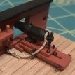
Final details and the finished model: Although they weren't actually the very last items done, I'm treating the lantern, the anchors and the flagstaff as the final details. The lantern was made from an old street lamp that I found in my model railroad scrap box. The lamp portion was heavily reworked and the brackets were made from brass rod and brass strip. The anchors were made using the kit castings with the stocks made from boxwood. The cable was run back over the bitts back to the main hatch. The anchor bouys were made from pieces of tapered dowel and then rigged. The flag staff is shown on the plans, although it seems awkward with the boom. I chose to install it mostly because I liked the way it looked.
Photos of the finished model follow the photos of the final detail work.
Bob
-
ccoyle got a reaction from EricWilliamMarshall in Part VI: Building V108 - The Superstructure
Building the skylights will introduce a couple of new techniques. There are three skylights on the model, built using parts sets 39 and 40.
Parts 39 are two larger skylights located abaft the superstructure...
...and parts 40 are the skylight abaft the forward stack.
The only thing difficult about building the basic skylights is that the parts are now getting somewhat tiny and awkward to work with (tweezers, people, tweezers). Parts 39a and 40a each have three fold lines to score, and the folds at the edges are almost 90 degrees, so the finished edge there will need some touch-up coloring (visible in the photos of the completed skylights). Score the lines, cut out the parts, and make the folds. When making the edge folds, it helps to grip the edge of the part with fine-tipped tweezers rather than pudgy fingers. Parts 39b and 40b are designed to fit inside folded parts 39a and 40a; medium-cure CA is useful in this situation to get the tiny parts to grip quickly and hold securely.
Parts 39a and 40a have the skylight hatches printed on them, but you may choose to add optional doubled hatches (parts 39c and 40c). These have tiny hinges, and the challenge here is how to cut the parts out without losing the hinges (if the challenge proves too difficult, just cut the hinges off - it won't make much difference). When cutting out tiny parts like these, there are two techniques that will help greatly. First, always cut away from inside corners, not towards them. When cutting, the edge of your blade makes about a 45 degree angle to the cutting surface, and thus the heel of the blade finishes the cut at the top of the paper before the tip finishes at the bottom. So, if you cut towards an inside corner of a part, the heel of the blade necessarily cuts into the printed area before the cut is completed all the way through the paper.
Second thing to be aware of is that as you draw your blade across a sheet of paper, you are actually pulling at the paper's layers of fiber. As a result, the last layer of fiber at the bottom of the sheet of paper may actually tear rather than cut cleanly. This isn't so bad on a large part, which can be trimmed, but it can be disastrous on ultra-tiny parts like the hatch hinges.
So how does one avoid this tendency to tear? Simple - one doesn't pull the blade! One pushes it instead, and here's what I mean: In the following picture, I'm cutting out one of the 40c skylight hatches. To cut the top edge of the hatch between the hinges, I start with the tip of my #11 blade right on the inside corner and push the blade down into my cutting mat. This downward push actually cuts more than half the distance from the first hinge to the second. To complete the cut, I reverse the part, and do the same thing starting at the opposite inside corner. I use this same push-cut technique to do all the cuts along the hinge edges as well.
I cut all the hatches out rectangular to start with, but the corners are actually very slightly round, so the corners need to be removed. The hatches are too small to effectively hold down with a fingertip while cutting, so I use the points of my tweezers instead.
Edge-coloring the tiny hinges can be troublesome, because the delicate hinges are easily damaged. For these, I hold my marking pen lightly against the inside corners and allow the paper to wick the color into the edges. Once all the hatches are cut out and colored, they are glued down to the skylights with PVA, and the finished skylights are mounted to the model.
-
 ccoyle got a reaction from qwerty2008 in Part VI: Building V108 - The Superstructure
That's certainly possible -- I downloaded mine years ago. Makes me wonder what else may have been updated.
-
ccoyle got a reaction from EricWilliamMarshall in Part VI: Building V108 - The Superstructure
Before starting the superstructure, take a few moments to study the diagram for that assembly. The cover sheet artwork also has a nice view of that part of the ship.
Assembly of the superstructure starts with wrapping the walls (23b) around the deck piece (23a). Score the fold tabs on 23b, along with the two fold lines where the wall wraps around the aft corners of 23a; after cutting it out, add the hatch door on the port side (part 55), Now here's another tip - if you apply contact cement to only one surface to be joined, it doesn't grab as tightly as when both surfaces are coated, but it does allow a small amount of working time. I glued 23a and 23b together with contact cement in the following order, applying the contact cement incrementally only to 23b: starboard rear corner, starboard wall, front of the bridge, port wall, port rear corner. When I got to the rear port corner, I discovered that the wall, 23b, was about 0.5 mm too long; if this happens to you, just trim the overage away from the end of the wall, crimp a new corner where the wall and corner meet, and then finish attaching the wall. After the wall is completely attached, the superstructure roof (23c) can be added using PVA. The finished assembly looks like this:
If you study the last image carefully, you can spot a minor error. While I was dry-fitting 23b around 23a, the assembly slipped from my fingers. It is a very rare person who can suppress the reflex to grasp at a dropped object, and I'm not that person! As a result, there occurred a crease in the forward bridge wall (it runs down through the front porthole). When card is creased like that, the crease is pretty much there forever.
Next, the superstructure assembly needs to be mounted to the main deck. The kit supplies a couple of joiner strips for this task (parts 23d).
I happen to dislike such joiner strips for this job. When paper is folded, the fibers in the paper have 'memory' - they want to return to their previous shape. As a result, folded paper acts like a weak spring. In this case, the folded joiner strips will have a tendency to push the superstructure assembly upward. To avoid this, and to do a better job of positioning the superstructure walls, I prefer to add locator strips to the model. These can be made from leftover chipboard or strip wood, if you have any lying around (what ship modeler doesn't?). Here, I've sliced some ~1 mm wide strips from the edge of a chipboard sheet.
These are then cut to the appropriate length and glued down to the main deck just inside the superstructure outline. The idea here is that the strips will position the walls exactly where they need to be, right on top of the outline. Notice I've cut and shaped a piece for the curved forward bridge wall as well. By the way, those colored patches on the deck are where I tested some markers for color matches to the kit.
I used ordinary white glue to mount the superstructure, because the fit with the locator strips is tight, and I wanted as much time as possible to get all the walls down over the locator strips. The mounted superstructure should look like this, with nary a bit of white peeking from beneath the walls:
Back to Part V: Building V108 - The Hull
-
ccoyle got a reaction from EricWilliamMarshall in Part VI: Building V108 - The Superstructure
Next up is the conning tower. The first thing to take note of is the parts are misnumbered. This is not an uncommon error in card models, where the model, the diagrams, the parts sheets, and the instructions are often all produced by one person -- without the benefit of a proofreader and perhaps also without the hindsight of a beta build. So, no big deal. The misnumbered part is 27d, which should be 24a. You'll also need 24b. 24c are the bridge wing support girders, which we won't need right away.
Normally, I would tell you to cut out 24b after scoring the fold lines and form it, but here's where you get the benefit of my building the model first. There's a big error with part 24b -- once it is cut and folded properly, it doesn't fit!
So here's how I fixed the problem. Cut part 24b apart along one of the rear fold lines. Measure and remove the excess part of the rear panel. We're going to put this excess colored panel to work. Notice that at the back of the conning tower portion of the parts 23 sub-assembly, there are two glue tabs; those should actually be part of the conning tower wall. Use the scrap piece from part 24b to make two rectangular panels to cover those glue tabs. The finished task will look like this:
Part 24b is now in two pieces. Glue the part with the rear wall to part 24a (the misnumbered '27d'). Now, use some scrap card to create a joiner tab for the two parts of 24b. Attach it thus:
Add the rest of 24b (don't forget to color edges as you work!).
So -- problem fixed. Next, add some joiner strips to the outline on top of the superstructure.
Glue the conning tower down with some white glue.
This assembly is a good example of the relative ease with which fit problems like this can fixed in the card medium. I don't think plastic or resin would have been as easy!
One other thing to take note of in this section is what happens when you create a 90 degree fold in card:
The ink layer is only on the very surface of the paper; very sharp bends will tend to crack this layer. Make sure to color the resulting exposed card fibers, either by painting or running a marker along the fold.
-
 ccoyle got a reaction from popeye the sailor in Part VI: Building V108 - The Superstructure
Next up is the conning tower. The first thing to take note of is the parts are misnumbered. This is not an uncommon error in card models, where the model, the diagrams, the parts sheets, and the instructions are often all produced by one person -- without the benefit of a proofreader and perhaps also without the hindsight of a beta build. So, no big deal. The misnumbered part is 27d, which should be 24a. You'll also need 24b. 24c are the bridge wing support girders, which we won't need right away.
Normally, I would tell you to cut out 24b after scoring the fold lines and form it, but here's where you get the benefit of my building the model first. There's a big error with part 24b -- once it is cut and folded properly, it doesn't fit!
So here's how I fixed the problem. Cut part 24b apart along one of the rear fold lines. Measure and remove the excess part of the rear panel. We're going to put this excess colored panel to work. Notice that at the back of the conning tower portion of the parts 23 sub-assembly, there are two glue tabs; those should actually be part of the conning tower wall. Use the scrap piece from part 24b to make two rectangular panels to cover those glue tabs. The finished task will look like this:
Part 24b is now in two pieces. Glue the part with the rear wall to part 24a (the misnumbered '27d'). Now, use some scrap card to create a joiner tab for the two parts of 24b. Attach it thus:
Add the rest of 24b (don't forget to color edges as you work!).
So -- problem fixed. Next, add some joiner strips to the outline on top of the superstructure.
Glue the conning tower down with some white glue.
This assembly is a good example of the relative ease with which fit problems like this can fixed in the card medium. I don't think plastic or resin would have been as easy!
One other thing to take note of in this section is what happens when you create a 90 degree fold in card:
The ink layer is only on the very surface of the paper; very sharp bends will tend to crack this layer. Make sure to color the resulting exposed card fibers, either by painting or running a marker along the fold.
-
ccoyle reacted to gjdale in Pt. V: Building V108 - The Hull
This really is a great tutorial Chris. The "warts and all" approach makes it seem that much more accessible to first timers.
-
 ccoyle got a reaction from BenD in Pt. V: Building V108 - The Hull
Ack! Almost forgot a few hull details.
Parts 21 are the propeller guards. Small parts like these that have substantial cut-out areas are flimsy once removed from the sheet, so it helps to do some of the prep work while they're still on the sheet. Start by coloring the reverse sides of the parts. Then, cut out the inside white areas, but leave the outer edge attached. You can then edge-color the interiors of the parts. When the interiors are done, remove the parts from the sheet and color the outer edge. Glue the guards to the hull with small amounts of PVA. Note that the guards follow the curvature of the stern, so the left and right guards are not interchangeable.
The rudder (part 22) introduces a new kit feature, the two-sided part.
Score the fold line, then cut out the entire rectangle containing the part. Apply glue to one-half of the back side of the part, then fold the rectangle in half. You now have a rudder colored on both sides! Remember, though, we're only using the part above the waterline, so go ahead and remove the red portion. Color the trailing edge and then glue the rudder to the stern; there's a locator mark there to help you. The rudder post will stick up above the deck just a little.
Here's the guards and rudder installed:
Okay, now we can move on to deck structures!
On to Part VI: Building V108 - The Superstructure
-
ccoyle reacted to Pete38 in Pt. V: Building V108 - The Hull
Very interesting.....Going to have to get my printer up and going so I can get in on this...
will be downloading the post and saving them on my computer...
Thanks very much....very nice and detailed tutorial
-
ccoyle reacted to JPett in Pt. V: Building V108 - The Hull
Ahoy Chris
Great build log. Thanks for taking the time to share. I will put one of these in my bucket.
-
ccoyle reacted to gjdale in Pt. V: Building V108 - The Hull
Me too! A new experience for me and I'm really enjoying following this. Definitely going on my bucket list!
-
-
ccoyle reacted to ianmajor in Pt. V: Building V108 - The Hull
Chris,
This is a superb tutorial both as excellent guidance and as a good read. I am looking forward to the next installment.