


newbuilder101
-
Posts
870 -
Joined
-
Last visited
Reputation Activity
-

 newbuilder101 got a reaction from Duanelaker in San Felipe by newbuilder101 (Sherry) – Scale 1:96
Thank-you Frank!
Well, I have another update. I've been working on the rudder with its pintles and gudgeons.
I used copper plate and cut it into strips which I formed on a 'dummy' rudder. Soldering was tricky for me at this scale, but I managed. I still have to fine tune and add faux bolts.
I've also made and added the midship set of spiral stairs with railings, and belaying pins are in place here as well. There is one more set of spiral stairs fore, yet to be made.
Last, but not least, I made the beakhead rails and supports. I'm not totally happy with them and some adjustments may follow.....or a total redo, I just haven't decided yet.
-
 newbuilder101 got a reaction from Archi in San Felipe by newbuilder101 (Sherry) – Scale 1:96
Thank-you Frank!
Well, I have another update. I've been working on the rudder with its pintles and gudgeons.
I used copper plate and cut it into strips which I formed on a 'dummy' rudder. Soldering was tricky for me at this scale, but I managed. I still have to fine tune and add faux bolts.
I've also made and added the midship set of spiral stairs with railings, and belaying pins are in place here as well. There is one more set of spiral stairs fore, yet to be made.
Last, but not least, I made the beakhead rails and supports. I'm not totally happy with them and some adjustments may follow.....or a total redo, I just haven't decided yet.
-
 newbuilder101 got a reaction from JLuebbert in San Felipe by newbuilder101 (Sherry) – Scale 1:96
It would seem that I am easily distracted on this build. I ended up doing a little side project that was not originally on my agenda.
I wondered earlier where the great cabin would be on a ship like this. Thanks to all the responses I was able to confirm the location.....in my mind the next logical step was to "dress it up" a little. I started with a walnut table/desk and just got carried away from there. The goblet and jug are wood as well. The Captain/Admiral's bed was a perfect fit.
I'm currently figuring out the best way to have some of this room visible and I have a couple of ideas.
-
 newbuilder101 reacted to Shazmira in US Brig Syren by Shazmira - Model Shipways - 1:64
Life is good Augie, still hectic, still living in a construction zone, but now I have an escape again, so things are looking up
-
newbuilder101 reacted to Shazmira in US Brig Syren by Shazmira - Model Shipways - 1:64
Well after a long protracted absence, I am happy to report the new drydock has been completed and I can resume modeling. I must say I really have missed it. Planking of the Syren has resumed, ad I hope to have some progress to show next week.
Here is the new drydock
-
newbuilder101 reacted to Remcohe in HMS Kingfisher 1770 by Remcohe - 1/48 - English 14-Gun Sloop - POF
I made an error in the building sequence and I should have installed the main mastpartner earlier. Now I got a bit into trouble getting it in at this stage. I had to take a shortcut and omitted half lapping the carlings under the deck beam. After the gratings are installed this won't be visible, but I'm confessing this error anyway :-)
Getting the pump tubes right was a bit of trial and error but after not to much work they were in place without to much hassle, I guess I was lucky today. I added iron bands at the end of the tubes from thin paper.
Remco
-
newbuilder101 reacted to shipmodel in Bristol Pilot Cutter by michael mott - 1/8 scale - POF
Hi Michael -
Really nice hinges. I used a similar method to make working hinges for the companionway door of a yacht America model some time ago. I do not have your skill with a jeweler's saw, so I used a length of soft iron wire inside to form the hinge barrels, and then cut straight through the whole thing with a metal cutting blade in the Preac. I think they came out pretty well.
Either great minds think alike, or fools rarely differ, whichever one applies. :-))
Dan
-
newbuilder101 reacted to EdT in Young America 1853 by EdT - FINISHED - extreme clipper
Young America - extreme clipper 1853
Part 124 – Skylights
There were two glazed skylights on the poop deck that provided light and sometimes ventilation to the cabin deck below. The two completed skylights are shown below.
The frames for the lights were made of interlocking parts with lap joints cut on the milling machine using a 1/32” bit in the setup shown below.
Slots were milled to one-half depth in a 3” thick pear blank, then sliced to size with a thin slotting saw blade on the Preac saw as shown below.
Slots for one long side/mullion and two short sides/mullions were milled into the blank. The next two pictures show the frame assembly. My shaky hands required the parts to be held in place for this work. I used sticky side up masking tape for this as shown.
The next picture shows the finished frame before final overall sizing and sanding.
The paneled walls for the skylights were made by the same method used for the companions, then painted white and fitted with natural wood corner posts. Both frames and a ridge rafter have been positioned on the aft skylight enclosure in the next picture.
In the last picture the frames have been glued to the enclosure and protective brass wire bars and wire hinges added.
After dropping this last frame into the cabin deck and fishing it out twice, I added the masking tape. This forward skylight was constructed with one side open, held up by two small wood supports. In this picture the after skylight has had beeswax/turpentine finish applied.
Ed
-
newbuilder101 reacted to riverboat in Alert by riverboat - FINISHED - Krick - 1/25th scale
"UP DATE TIME"......... I just finishd up the main mast rigging and put the name on the stern''''
looks like I got all of the ropes tied off to where they're supposed to be,if not I can always say the Capt. is trying out a new belaying plan. No major problems were encountered on this journey, (again, thanks to Dirks excellent build) The mizzen will be next, then I'll add the jib sails....... I still need to add ropes to the cleats and belaying pins, but that will be the last thing I do along with the oars, and the rope railing.
Thanks for look'n in!!
Frank
Thanks again for look'n in.......
Frank
-
newbuilder101 reacted to mobbsie in Bomb Vessel Granado 1742 by mobbsie - FINISHED - 1/48 - cross-section
Further to my last post I do have some more pics of the stands
I hope that helps.
Be Good
mobbsie
-
newbuilder101 reacted to EdT in Young America 1853 by EdT - FINISHED - extreme clipper
Young America - extreme clipper 1853
Part 122 – Ladderways
With the two larger deck cabins constructed, it was time to turn to the several smaller deck structures. These include three companionways, two skylights, two small lockers at the forecastle break and the paneled housing for the rudder mechanism. I thought this work would be the next logical step, before moving on to the several fife rails and the machinery – the windlass, bilge pump, capstans and wheel.
In preparation for making and placing ladders and stairs – work that must be done before constructing the companion structures – I had to finally decide the time period to base the model on. Young America had a long life – 30 years. Changes were made. I had tentatively decided to aim for the period after installation of the Howes double topsails (1854) and after pole masts were installed above the topmasts (1860’s?). Apart from my interest in these features, the two existing photographs of the ship were taken after these modifications. These photos are the best primary data source available and I spend a lot of time going over them with a magnifying glass. The photos clearly show two features that differ from the basis I initially used for the drawings and model. First, the entryway is shown well aft, adjacent to the mizzen mast. Also, there is a large area of each upper bulwark removed astride the main hatch. This was undoubtedly to facilitate loading and unloading cargo. The first picture shows the modification of the bulwarks to incorporate this feature.
This change also required modifications to the pin rails to move belayed rigging clear of this area. The next picture shows me cutting the new entryway on the starboard side. The pin rails in this area were also cut out.
The decision was now irrevocable, so I can stop thinking about it. The next picture shows the completed entryways.
The method I use for stairs and ladders was fully described in Naiad, Vol II and to some extent in earlier posts. I use a milling machine to precisely set the angle, depth, and spacing of the treads on the stringers. The first picture shows this in progress.
Mirror images of the cuts need to be made. The stringer material is 4” thick and the slots are cut 2” deep and 9” apart. The blade is about 2 ½” thick. I used a 4” (actual) diameter blade so the work will clear the underside of the motor. You can see by the shortness of the last two cuts that I ran into the column on the mill – but there was still enough material to make all of the 25 degree stairs. The ladders at the entryway were 15 degrees. This piece was then ripped into stringer pairs.
The next picture shows a pair with treads being fitted.
After installing the first two as shown, I fitted the other stringer and then slid in the remaining treads. The next picture shows the finished assembly being sanded to even out the treads.
The next picture shows a stair assembly fitted into the aft main deck hatch. There are three of these companion hatchways.
The last picture shows six of the nine ladder assemblies installed.
There is also one into the forward hatch and two at the forecastle break. These last two were made but will not be installed until the windlass is in place. With this work done, the companionway enclsores can be constructed – next time.
Ed
-
newbuilder101 reacted to michael mott in Bristol Pilot Cutter by michael mott - 1/8 scale - POF
Thank you all for the positive feedback.
Here is a Step by Step of the preparation of the light frame for the skylight. The way of working at the computer desk is different that in the workshop in that I am only able to use small hand tools at the desk. With a little preparation a high level of accuracy can be accomplished with simple tools.
To be fair I started with a few strips that were prepared in the shop on the table saw.
the first task was to cut the profile to length, using the square vice that I use a great deal for both machine work and hand work. the design of the vice is almost the same as this one with the exception that mine has a dovetail slide and I made it myself as an apprentice 52 years ago.
Next the lengths are squared up using the shooting board hooked onto the edge of the desk with a sanding stick instead of a block plane.
The sanding stick has the sandpaper set in such a way that the sandpaper cannot wear away the shooting board by removing a strip from the bottom like this.
I have a number of these sticks made from scraps of dimension lumber such as 2x4 the section varies depending on what I have available but I like to keep enough material so that is stays flat and square on the board. a little candle wax keeps them well lubricated on the bottom. I also generally use both sides each a different grit. I mark the ends for quick reference.
To cut the 45 degree corners on the top and bottom rails I just clamped a steel 45 degree square to the shooting board.
The way I use the board is to shift the work out a little so that I can see how much will be sanded off like this you can see there is a gap close to the stop.
After sliding the stick back and forth a few strokes the stick ceases to cut like this
Rinse and repeat as much as needed to remove the require amount, this works much faster that one would first think, I use this method far more that a powered sanding disk.
The next task is to cut away the areas on the vertical sides this is done by transferring the angle to them from the top and bottom rails then cutting away the waste with the jewelers saw.
The cut pieces were then cleaned up with the square file that has 2 edges polished smooth as safe edges this is one of my favourite files.
then they are ready to be glued up.
Michael
-
newbuilder101 reacted to michael mott in Bristol Pilot Cutter by michael mott - 1/8 scale - POF
Thanks for all the positive comments and likes it is very encouraging, and appreciated.
The recent file organization has been completed and during the process I was able to fix a few photo issues in some of the early posts, a couple of links have gone AWOL (the nature of the net it seems).
This evening I continued the work on the skylight.
The frame material has been roughed out for all four lights. these are the 3rd and 4th sets
This is the second frame glued up.
and some in situ shots.
Once all the frames are assembled I will make a few more hinges the same way as the ones for the cabin doors, I will also add the wooden bars with the horizontal metal bars to protect the glass (lexan).
Michael
-
newbuilder101 reacted to Sjors in HMS Agamemnon by Sjors - FINISHED - Caldercraft/Jotika - 1:64
We are almost back to normal !!!!!!
Work, work and work.....
But we are happy.
And a small update.
The large gunport lids on the starboard and port side are done.
All what is left are 14 small gunport lids ( and of course the rest what I have to do )
And back to work again !!!!!!
Sjors
-
 newbuilder101 got a reaction from Vivian Galad in San Felipe by newbuilder101 (Sherry) – Scale 1:96
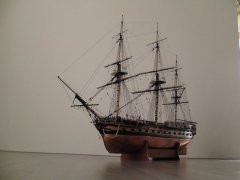
Thank-you Frank!
Well, I have another update. I've been working on the rudder with its pintles and gudgeons.
I used copper plate and cut it into strips which I formed on a 'dummy' rudder. Soldering was tricky for me at this scale, but I managed. I still have to fine tune and add faux bolts.
I've also made and added the midship set of spiral stairs with railings, and belaying pins are in place here as well. There is one more set of spiral stairs fore, yet to be made.
Last, but not least, I made the beakhead rails and supports. I'm not totally happy with them and some adjustments may follow.....or a total redo, I just haven't decided yet.
-
newbuilder101 reacted to EdT in Young America 1853 by EdT - FINISHED - extreme clipper
Young America - extreme clipper 1853
Part 121 – Coach
The coach was really just a vestibule at the break of the poop to provide access from the main deck to the entrance of the “mezzanine” level cabin deck below. It is an interesting and intricate structure. Its forward end is just large enough to fit an entrance door on each side and that part is supported on a coaming on the main deck. The aft part merely provides headroom above the main deck level over the head of the staircase that leads down to the cabins. At the break of the poop is a double-door entrance to the head of the cabin deck staircase. As mentioned before, the design of all this interior work is speculative.
The first step was to make and fit the starboard side panel on the coamings on both decks and to the bulkhead at the break of the poop. In the first picture that wall has been built up of planks in the usual way and then cut to fit. In the picture the forward corner post is being glued on.
In the next picture the studs on the inside of the wall have been installed and the door opening cut out flush with those members using the circular saw for most of the cut length.
A panel for the entrance door was then cut and fitted to reinforce this very fragile structure and provide a base for the door paneling. In the next picture the panel is being glued in.
The outer door jambs and header are being added in the next picture.
In the next picture the door has been paneled inside and out and the wall installed on the coamings.
I made the doorway into the cabin itself a bit more ornate, using the same wood and trim style used in the cabins as shown in the next picture.
In this picture the double doors have been fitted with simple brass hardware. As with the cabin woodwork, I used black walnut for the doorway. In the next picture the finished forward bulkhead is in place and aft bulkhead is being glued in.
The wall on the port side consists only of the stud framing – to provide some visibility to the interior. In the next picture that framing has been installed and other work is in progress.
In the picture the overhead rafters have been installed as well as the structure and panels on either side of the doorway. The exterior end trim pieces are being glued on in the picture. The last picture shows the freshly painted roof on the finished coach.
This picture also shows a new entryway on the port bulwark and some modifications that I will explain in the next part.
Ed
-
newbuilder101 reacted to EdT in Young America 1853 by EdT - FINISHED - extreme clipper
Young America - extreme clipper 1853
Part 120 – Main Deck Cabin 2
Work on the deck cabin continued. In the first picture the starboard side has been installed and the forward bulkhead is in the process.
All the bulkheads were made to fit into the rabbet on the coaming. In the next picture, both end bulkheads are in place and the framing for the port side is being installed.
Pine strips with wedges were used along the floor to hold the studs against the coaming at the bottom. The reinforcing pine batten is still pasted in place. This side of the structure will be left open for visibility into the framing below.
In the next picture the pine batten has been removed and masking tape has been placed on the deck framing to prevent small pieces from dropping through. These can now be very difficult to extract. The first of the rounded up roof rafters are being fitted.
In the next picture these have been installed. A number of them have been fitted with hanging knees to provide some wind bracing. This structure had to be quite strong.
In the next picture the masking tape has been removed and the tops of the end bulkheads trimmed out in readiness for the roof planking.
The next picture shows the initial strake of 3” x 7” roof planking being aligned against a straightedge and pinned in place.
There is a strake with a water stop to be fitted outside of this one, but I wanted to paint that first and use the next inner strakes for alignment. The next picture shows that outer strake being fitted against the two initially installed planks.
In the next picture the planking has progressed almost to the centerline.
The last picture shows the finished roof.
The ends of the planks have been sanded square and notches cut through the water stop for the two transverse skid beams that will cross the roof. The roof has been coated with acrylic sanding sealer, sanded smooth and painted with the same color blue as the waterways. The paint is acrylic.
The next task is to construct the coach – the entrance to the cabin deck.
Ed
-
newbuilder101 reacted to michael mott in Bristol Pilot Cutter by michael mott - 1/8 scale - POF
Thanks for all the positive feedback.
After gluing the case together the ends of the channels needed a little more work in the way of small extensions so that the water doesn't just trickle down the side and ends. This was accomplished by taking a small strip of mahogany, and milling a groove the same as the channels then shaping the outside curve to create a cup like extrusion.
This end was then rounded with files and sandpaper Oh and i had some help
these were then cut off with a jewelers saw and glued to the appropriate locations.
The side channels were a little more tricky to cut, and had first to be sanded to the same angle. I did this by placing the cup shaped piece on the side of the case and finishing the end with the sanding block.
Cutting these off was done slowly with the jewelers saw with my finger underneath the end to act as a support, As the blade neared the bottom of the curve I used a micro back and forth motion until the cut parted off the pieces.
these were then glued to the sides
After all the extensions were glued and set they were cleaned up with some 400 grit sandpaper.
The top bar was then shaped with a block plane and files and connected to the case with a couple of brass woodscrews from below.
Next the hinged lights need to be made and fitted.
Michael
-
newbuilder101 reacted to Dan Vadas in HMS Vulture 1776 by Dan Vadas - FINISHED - 1:48 scale - cross-section - from TFFM books
Thanks Greg.
The first pieces of the frames have been cut. I've made all the Floors first, as they are the thickest at 10 (scale) inches thick. If I run out of Pear before the new stock arrives I'll be able to run the remainder of my thicker stuff, including the leftover from the 10", through my Thickness Sander to get the thinner Futtocks and Toptimbers.
The Port side of this Cross-section will be fully planked inside and out as was the full model. I'm using simple scarph joints on the planked side - the open side will have Chocks between all the futtocks.
Note that these pieces are virtually straight off the scroll saw - there's a bit of finessing to be done yet. Every 2nd frame has a Floor, so only half of them are in these pics. Nothing has been glued in yet :
Danny
-
newbuilder101 reacted to Sjors in HMS Agamemnon by Sjors - FINISHED - Caldercraft/Jotika - 1:64
Thanks again for the warm welcome from me and Anja......
Anja is not around for a while here, because of other things that keeps her busy .
But she send her regards to all of you !
@ Jan,
All the finished models are not in this house....
I was afraid for damage when I move them, so they are at a school close at the old house.
All the young kids can watch it and I'm happy with that solution.
@ Wim,
Thanks.
I will give that a try !
Sjors
-
newbuilder101 reacted to augie in HMS Agamemnon by Sjors - FINISHED - Caldercraft/Jotika - 1:64
Welcome back, Sjors and Anja. I'm smiling again!!!!
-
 newbuilder101 got a reaction from Sjors in San Felipe by newbuilder101 (Sherry) – Scale 1:96
Thank-you to all for your kind words! We do have quite a wonderful community here at MSW!
-
 newbuilder101 got a reaction from Burroak in San Felipe by newbuilder101 (Sherry) – Scale 1:96
Thank-you to all for your kind words! We do have quite a wonderful community here at MSW!
-
newbuilder101 reacted to michael mott in Bristol Pilot Cutter by michael mott - 1/8 scale - POF
Thanks one and all for all the kind comments and congratulations
Here is the gang in the style of who's on first
My eldest son is holding my new granddaughter who was born to my youngest son and wife, right in front of me is my eldest granddaughter, born to my eldest son and his wife next to my eldest grandson who is a brother to the youngest granddaughter behind his cousin who is who is the nephew of my youngest son who is behind my third oldest grandchild.
Oh I have no idea who the thin guy in the back is.
Michael
-
newbuilder101 reacted to Remcohe in HMS Kingfisher 1770 by Remcohe - 1/48 - English 14-Gun Sloop - POF
Ok here we go.
When cutting a brass rod with a sharp knife a burr is created, I use this both to my advantage and at one point it needs to be removed (otherwise you'll have trouble inserting the bolt in the predrilled hole. Here are the steps involved:
1. This is the rod after the last bolt was cut
2. The burr is removed using a small steel ruler
3. A new diagonal burr is created to have the bolt firmly set in the predrilled hole ( I use bot 0,5 mm brass rod and a 0,5 mm steel drill to drill the holes, without the diagonal burr the fit is a bit loose)
4. Cutting off the bolt creates a burr this is the dome of the bolt
Tools needed (I won't cover the use of Liver of Sulphur which I use to blacken the bolts after they are in place):
Step 1 This is the rod after the last bolt was cut
Step 2 The burr is removed using a small steel ruler
Step 3 A new diagonal burr is created by rolling a sharp blade overt he rod to have the bolt firmly set in the predrilled hole
Step 4 Cutting off the bolt creates a burr this is the dome of the bolt
I use a brass rod with a small hole in the point to push the bolt into place leaving the dome of the bolt proud to the surface. When the are all done I treat them with liver of sulphur to blacken them.
The end result (it's hard to capture but each bolt has a nice subtle dome):
Remco