

sonicmcdude
-
Posts
174 -
Joined
-
Last visited
Reputation Activity
-

 sonicmcdude reacted to Bluto 1790 in HMS Leopard 1790 by Bluto - FINISHED - 1:80 - 50 gun ship - PoB
Catheads now a permanent part of the ship and the foredeck planking is underway >>>
WHEEE !!! ~ Leopard is now 'all decked out' >>>
The foredeck planks are still to be scraped and sanded . . . then it's onto the other million or so things that are all part of the ship . . .
. . . . .
-
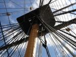
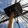
sonicmcdude reacted to AntonyUK in HMS Victory by AntonyUK - FINISHED - Scale 1:36 - cross-section
Hi Shipmates.
Thanks for looking in MIJ and Bob
A little update.
The Ryders and the racks are finished.
Copper pinned the Ryders tonight and will photograph them tomorrow.
Photo of ryders before copper pinning. And Racks.
Ryder fitted but not fixed yet.
Ryder center bridges will be fitted and shapped on the Ryders being Fixed in place. Not possable to do so until they have been assembled and fixed.
More tomorrow.
Regards Antony.
-
sonicmcdude reacted to Ilhan Gokcay in Matthew 1497 by Ilhan Gokcay - FINISHED - Scale 1/50
....
For large and more detail photos see also: http://www.flickr.com/photos/ilhan_gokcay/sets http://www.flickr.com/photos/ilhan_gokcay/sets/72157626433922489 http://www.flickr.com/photos/ilhan_gokcay/sets/72157626433922489/page16
-
sonicmcdude reacted to Ilhan Gokcay in Matthew 1497 by Ilhan Gokcay - FINISHED - Scale 1/50
...
For large and more detail photos see also: http://www.flickr.com/photos/ilhan_gokcay/sets http://www.flickr.com/photos/ilhan_gokcay/sets/72157626433922489 http://www.flickr.com/photos/ilhan_gokcay/sets/72157626433922489/page16
-
sonicmcdude reacted to Ilhan Gokcay in Matthew 1497 by Ilhan Gokcay - FINISHED - Scale 1/50
Attached the main sail and belayed its rigging.
For large and more detail photos see also:
http://www.flickr.com/photos/ilhan_gokcay/sets
http://www.flickr.com/photos/ilhan_gokcay/sets/72157626433922489
http://www.flickr.com/photos/ilhan_gokcay/sets/72157626433922489/page16
-
sonicmcdude reacted to EdT in Young America 1853 by EdT - FINISHED - extreme clipper
Young America - extreme clipper 1853
Part 13 –Frame Assembly 2
American Clipper Note: In 1848 there were 9 sailings recorded from New York to San Francisco and they averaged over 150 days. The following year, 1849, after the gold discovery, there were 37 passages averaging 177 days – for those that made it. From 1850 to 1853 - as the extreme clippers came off the slips - there were around 375 voyages averaging 128 days. In her maiden voyage Young America did it in the excellent time of 110 days. This was longer than the record of 89 days, 21 hours set by McKay’s Flying Cloud in 1851, but up to the end of 1853, times of under 110 days were achieved only 41 times in the 375 passages.
The first picture shows frame pair A with the pins removed after assembly.
The was the first pair forward of the deaflat, so there is virtually no bevel. The next picture shows the assembly being sanded back to the aft profile on the disk sander. The inside was cleaned up using a spindle sander, but left rough.
At this stage the outer profiles are accurate enough to set the frame, so the patterns can be removed. This will allow the sidings of the upper timbers to be reduced.
Reducing the sidings after assembly will allow the frames to be accurately beveled based on the patterns, which would be inaccurate for the timbers with reduced siding. Also, it is much easier to assemble the timbers using pins if they are all the same thickness. The drawback is that timbers have to be reduced on the finished assembly.
The safest way to do this – for you and the work - is filing by hand as shown in the next picture.
The sidings step down by an inch of so at each joint moving upward, so this can be done by filing then measuring.
With so many frames to do, I adopted two other methods to speed the process. The first is shown in the next picture.
In this method a ¼-inch end mill is lowered down to touch the piece. The piece is then removed and the cutter lowered to make the cut above the joint. Do not even think of doing this without the guard and without being able to hold the piece on two sides as shown. Although the amount to be removed at each level is small, I did this in stages of about .005”.
The next picture shows how the remaining ends were done after the above step using the disk sander.
Both these last methods require a lot of care.
After a few frames, I decided to install the top timbers – cut from thinner 10” stock - on the forward frames after all this work. These will be visible inside the hull planking above the main deck, so this way they will all be the same size. The next picture shows a top timber.
In this picture the iron bolts have been installed. The next picture shows that work in progress.
As on Naiad, I used black monofilament for these iron bolts, held in with CA glue.
The last picture shows the final midship frame, ready to be erected.
Ed
-
sonicmcdude reacted to Albuk in Bracera (Brazzera) by Albuk
Finally, the second layer planking is over. I stained the planks with blue stain and although I like it, plywood didn't go as well. The layers are visible on stronger light. I'm still thinking whether to leave it as is, or paint.
Next, I will paint the hull below the water line with white matte color but before that, I have to do some metal work, for which I got my hands on a 0.3mm brass plate. The copper sheet that came with the kit is very, very thin... more suited for coppering.
-
sonicmcdude reacted to NenadM in Sonic's TRITON POB 1:72 first build
Sinan, this is real thing. No Tehnodidakta
-
 sonicmcdude got a reaction from NenadM in Cutty Sark by NenadM
Awesome progress Nenad! You made her in to beauty. I'm interested about the plans from Tehnodidakta are they available today? Thanks for sharing your build. Pozdrav
-
 sonicmcdude got a reaction from Erebus and Terror in HMS Terror by Erebus and Terror - FINISHED - Scale 1:48 - POB - as fitted for polar service in 1845
This is going to be a nice build, I like the plans.
-
 sonicmcdude got a reaction from Jeronimo in LE BONHOMME RICHARD by Jeronimo - FINISHED
The ruler is awesome idea Karl!!! This is a nice addition to a lathe and is nice homemade and it cost noting to
-
sonicmcdude reacted to Jeronimo in LE BONHOMME RICHARD by Jeronimo - FINISHED
Hi friends,
thanks for the kind comments.
Greg,
Centring ruler by the company PROXXON.
Material for the hoops / rings is black paper carton.
Regards Karl
-
 sonicmcdude got a reaction from nobotch in All my homemade tools
Hi all.. this is my all homemade tools in one post.. maybe someone will need some idea
-
sonicmcdude reacted to Jeronimo in LE BONHOMME RICHARD by Jeronimo - FINISHED
Hi federicoaa,
some pictures of the construction the barrels.
Karl
-
 sonicmcdude got a reaction from Wishmaster in Matthew 1497 by Ilhan Gokcay - FINISHED - Scale 1/50
Three words: master ship builder
-
sonicmcdude reacted to Ilhan Gokcay in Matthew 1497 by Ilhan Gokcay - FINISHED - Scale 1/50
Attached the sprit sail and fore sail to the masts and belayed their rigging.
For large and more detail photos see also:
http://www.flickr.com/photos/ilhan_gokcay/sets/
http://www.flickr.com/photos/ilhan_gokcay/sets/72157626433922489/
http://www.flickr.com/photos/ilhan_gokcay/sets/72157626433922489/page15/
-
sonicmcdude reacted to harvey1847 in HMS Triton 1773. POF. 1:48. Daniel
Hello all!
Small update, I have been making the steps on the stem deadwood. It took me a while. I still have doubts about this piece. It seems to be beveled just a little bit, as seen in Wang´s Triton, so I will wait for the frames raised up (not glued) and try to imagine it out.
As you can see I stopped the step on the “W” frame. The hawse pieces will rest between the stem post and the “W” frame so I will not “weak” that zone by beveling where the W frame ends. (I do not know if this makes sense)
Another important thing about the device for the rabbet (see post #52). It worked superb when the fiber of the timber was straight but it did not work when the fiber was cross or not quite aligned. So I had to do it by hand using a small x-acto blade. Fingers cross with the keel…
I also made the six patterns using CAD for the angles or the fore cant frames. The idea is to glue them to a piece of wood or cardboard and put them against the disc sander table to get the right angle. My table can tilt till 45º. Here is the pdf file just in case any of you are at that stage.
angles tilt sander_A4.pdf
Hope to post some more in a week or so.
Happy Autumn!
Daniel.
-
sonicmcdude reacted to Dida in Sonic's TRITON POB 1:72 first build
Hi, Sinan!
Did you get tired like me with all those frames? I put my model little bit aside.
-
sonicmcdude reacted to JerryTodd in HMS Macedonian 1812 by JerryTodd - 1:36 scale - RADIO
Fiberglass
With frames set in and the hull's shape stable, it was time to glass the outside.
I started with the transom
Then the portside
Once that had set-up, it was on to the starboard side
There, that wasn't so bad
Excess resin went into the bilges and on the lower frames.
After the glass set-up and was sanded, there were some blisters where the glass didn't lay and bond to the hull, these came off while sanding and were filled with auto-body putty. More sanding and another coat of resin brushed on, then sanding again. Some clean up and degreasing and it's...
Wale Ho!
On this model the wale isn't the structural member it is on a real ship, but I did want it done in an anchor-stock pattern as it would be visible on close inspection.
I started by cutting a block of white pine, as used for the rest of the planking, to the offset anchor-stock shape, then slicing off 1/8" thick planks.
I started on the starboard side by marking the positions of each plank on the hull from the bow aft, and actually started gluing them on amidships. I used CA to attach them to the hull, and Titebond III to glue them to each other.
Clamping them to the hull took some thinking at places, as did clamping them to each other without lifting them off the hull.
At the bow the pieces needed to be precurved, so the SBJ (Sophisticated Bending Jig) was employed. The pieces were wet, clamped in the jig, and left overnight.
It took a little over a week, but the starboard wale was done. Now to the port side!
I took a slightly different approach this time. Clamping the pieces to the hull was quite tedious, so I used the nails I used to hold the planking with during construction to hold the pieces onto the hull here. This made things go much quicker and smoother.
Before starting though, I cut out a gunport just for fun. I was afraid the hull would flex with the ports cut out, but I need them cut before I frame up the hull thickness behind them, because that framing sets into the gunport opening a bit. Actually, the planking is set back creating a rabbet for the lid to close against.
My friend Mark was building a crabbing skiff at my place, and while he had the epoxy out, I stole a bit to give the wales a couple of coats
I then started carefully cutting out each gunport opening. Once all the gun ports are cut out along the gun deck, the internal framing will go in around each one, making the hull the right thickness as seen through the gunports. The focs'le and quarterdeck ports will be cut after they're framed and the external moldings have been installed.
-
sonicmcdude reacted to JerryTodd in Pride of Baltimore by JerryTodd - 1:20 scale - RADIO - as she appeared in Fall 1981
Spars
All the spars were made of white pine, since it's been working so well so far.
Rough cut to size, square stock was made 8-sided, etc, etc, to round.
Gaffs and boom were fitted with jaws made from aircraft plywood and tried for size.
The boom has a shoulder cut in the end for the ring-tail iron and a bolster that keeps the mains'l clew out-haul held off the boom.
The main mast was fitted with a saddle and knees for the boom to rest on, after the mast's hoops were loaded on.
All the spars got stain and paint, and all the brass was blackened and painted. The coarse yard got stuns'l boom irons, stuns'l booms, and jack stays.
Cleats and holes for sheets and the like...
and a clew iron for the main boom
The yards and boom
-
sonicmcdude reacted to Gaetan Bordeleau in Le Fleuron by Gaetan Bordeleau - FINISHED - 1:24
Here are few notes about the construction a part which is a very good example for the use of the milling of the holes for the sheaves which is done in 3 steps:
The length of the milling cutter being about the half of the thickness, grooves are milled half way
A drill bit is use to break through the part. These holes bored at one end only will serve as references to mill the other half of the thickness
The part is then turned 180 degrees and the other half is milled
Then the scroll saw which has to cut some angles which are about 1 inch thick needs the appropriate blade. Mainly I use 2 kinds of blades from Olson; one for thin and one for thick cuts. I am not sure about the name but it is about skip-tooth or reverse tooth . No sanding is required after the cut. The combination of the Hegner scroll saw and the blade allows to cut in straight line with precision and even to cut as thin as paper if required and with 0 vibrations.
I tried to work at different heights on the table and I continue to believe that working at the ‘’good’’ height makes the difference at least it makes the job easier. As an example, here is a picture in Junghans German watch office. Another advantage for the Jewelers to work on a high table allows them to see their work closely.
-
sonicmcdude reacted to harvey1847 in HMS Triton 1773. POF. 1:48. Daniel
Hello People!
At last something to post on! I could not make some work since June… three months doing nothing but frames and doors for my house. I have been around visiting amazing logs and willing to post something like I am actually doing
.
Someone said once “do not attempt to do all the frames, just do them one by one and raise them”. Well as you can see I went the tough way and now somehow I can see the hull in some way. Now I know I am going to be able at least to make the whole structure.
Here are some pics. I did all of them in just one month more or less.
All the frames ready to put in order.
Nice and clean...
Our dinner tonight, Kebabs rolls for all.
Or maybe ribs...
NOW the fun thing starts since I have all the frames. Thank you all for the nice words during these months!
-
sonicmcdude reacted to Jeronimo in LE BONHOMME RICHARD by Jeronimo - FINISHED
Hi friends.
A. Hold - Lagerräume
9 Magazine and Powder-rooms
Lager-und Pulverkammer
B. Orlop - Unterdeck
12 Bread-rooms
Brot-Lagerraum
Regards Karl
T e i l 3 4
-
sonicmcdude reacted to Jeronimo in LE BONHOMME RICHARD by Jeronimo - FINISHED
Hello friends,
new pictures of the construction , BHR model.
Karl
T e i l 33
-