lehmann
-
Posts
129 -
Joined
-
Last visited
Content Type
Profiles
Forums
Gallery
Events
Everything posted by lehmann
-
 Here's another point for your time history of the Wasp. I found this in an excerpt of "Naval Adventures During 35 Years Service" by Lt. W. Bowers, RN. ,Vol1. 1, pp 272-302, 1833, reprinted in "Every Man will do his Duty", by Dean King, Henry Holt & Co. 1997. Pg 397 and the original can be found at: https://books.google.ca/books?id=raZCAQAAMAAJ&pg=PA35&lpg=PA35&dq=Naval+Adventures+During+35+Years+Service&source=bl&ots=u18CL6y2pd&sig=_OMrHxcsRwkRG8NEG1lNLOifHIE&hl=en&sa=X&ved=0ahUKEwj83aDc98_LAhUP8GMKHXdmC78Q6AEIHjAB#v=onepage&q=Naval%20Adventures%20During%2035%20Years%20Service&f=false Wm Bowers, serving on the HMS Helicon on station off the Scilly Isles. "About the beginning of July [1814] we received orders to proceed to the longitude of 12 deg West, to join our old consort the Reindeer; .... Approaching our ground, we fell in with the Achates, Captain Langhorn, and the following day discovered the wreck of a vessel's mast and rigging floating in the water. ...on sending a boat to examine the wreck, the evidence afforded by the grape shot sticking in the mast, the marks and dimensions of the main cap, the sails and rigging, left no doubt of the Reindeer's fate. The main mast appeared to been burnt off by the copper in the wake of the main boom. Everything denoted that the strife had been sanguinary, and the catastrophe recent; whoever had been the antagonist, he had found tough work. ...At the end of the week, we returned to the spot, where we discovered the wreck of the fore-mast." A footnote is provided: The following are the particulars of the action received from one of the survivors: "The enemy, (the Wasp, American corvette) was discovered on our lee bow about 10 AM [on June 28, 1814] standing toward us...." The foot note continues to discuss the battle, the death of Capt. Manners and wounding most of the other officers. Overall, 70 of 109 crew killed or wounded. The "brig a perfect wreck, so as to be unmanageable, we were compelled to strike." After reading the history of the Wasp on Wikipedia, I wonder how much damage accumulated during so many battles in a short time without the ability to to do a major refit. The Wasp was larger than any of its opponents, but it is unlikely to get away unmarked. For instance, the battle with Reindeer was against carronades at short range, so there must have been damage to the hull and perhaps the spars. Could structural weakness have contributed to loose in a storm?
 -
Bandsaw blade tension problems
lehmann replied to grsjax's topic in Modeling tools and Workshop Equipment
I suspect there was a manufacturing defect in the spring. Is it still on warrantee? Keeping a spring loaded should not cause it to fail. If that were a problem for spings, your car suspension would soon collapse. The same applies to a bandsaw blade, which is basically spring steel bent over the wheels. The failure of springs and sawblades is repeated loading above a certain stress level that causes a fatigue crack. In the case of bandsaws, the highest stress comes from bending over the wheel every time the blade goes around a wheel. Actually, saw steel is very high strength, so you need an extremely high load to pull it apart in tension. Assuming the steel was properly heat treated, and weld is properly annealed, the main reason for early failure is a defect/impurity in the steel or a scratch/knick on the surface which acts as a stress concentration. -
I'm wondering if the plank isn't tight against the bulkhead. White glue (PVA) is quite viscous, so if the clamping pressure isn't high enough to squeeze out the glue then plank and bulkhead won't come together. Other makes of glue, such as Titebond, are much thinner. I'm not sure of the chemistry of PVA glue, but I think you can water it down (only very little water is needed) to thin it out. As a test, lay some strips on a flat surface at the distance of your bulkheads. Then glue a few planks to the strips. With some, apply the same clamping pressure as was used on the model, and on others, use a c-clamp or heavy weight. FYI, with white glue you should coat both surfaces, but you only need a transparent coat - just get the wood uniformly wet. If you can't see the wood color through the glue, you've put on too much. For furniture making, the thinner the glue line, the stronger the joint. It also means there is less squeeze-out glue to clean up.
-
Greg, Wood swells with moisture, but not that much. It looks more like the planks do not have consistent thickness. The eye can see a step of few thousandths of an inch if the lighting is right. Have you checked the thickness with a caliper or micrometer?
-
Tool for Shaping Brass Strip
lehmann replied to mikiek's topic in Metal Work, Soldering and Metal Fittings
Here's another thread on softening/hardening brass http://modelshipworld.com/index.php/topic/11363-re-hardening-brass/ -
Mike, You can make wider planks by edge gluing narrow planks. It may look strange if you're not painting or coppering. If you use steam or hot water for making the planks pliable for bending, check whether the glue will hold up. I use heat from a modified soldering iron for bending. Fish glue stands the heat well.
-
Size of blocks & rigging thickness ?
lehmann replied to Senior ole salt's topic in Masting, rigging and sails
Get a copy of Lennarth Petersson's book "Rigging Period Fore-and-aft Craft" He does not provide a scaled rigging plan for and English Cutter, but he shows an individual drawing for each rope, including blocks and fittings involved. A belaying plan is provided. Here's another post to look at http://modelshipworld.com/index.php/topic/4855-cutter-rig/ for rig plan and spar proportions. -
Seeking information on determining load waterline
lehmann replied to trippwj's topic in Nautical/Naval History
If I may summarize Bourne's method: take the lines of the hull and build a scale model, in this case, 1/48 scale, measure the volume of water displaced by the model then multiply by 48 cubed and the density of water. Do you have any indication this method was used? I suppose it is one use of half hull models. I recall reading that this method is somewhat error prone, with the main problem being that the wooden model absorbs water. It reminds me of another way to measure measure area: trace the shape onto paper on cardboard and weigh it. Also weigh a piece with a known area. Area of the irregular shape calculated by simple ratio. -
Seeking information on determining load waterline
lehmann replied to trippwj's topic in Nautical/Naval History
Having done displacement calculations by hand using Simpson's rule, I can attest to the tedium and the chance of error. The use of a planimeter (integrator) makes a world of difference. However, as I've mentioned before, knowing the displaced volume is only the first, and easiest, part of the calculation (estimation) of the load water line: the second is the weights of the ships components (framing, planking, spars, anchor chain, etc), which could easily have a 20% error band. A planimeter could be used with the volume calculations of frames, assuming you have drawing for each component, etc, but there's still significant uncertainty in the density of wood. And, if you want to calculate the stability, you'll need to estimate the center of gravity of all those components as well. With a 3D drafting application, this can now be done, but by hand it would be a nightmare, even with the Amsler intregrator. Up until the time of building steel or aluminum hulls with 3D drafting, weights were likely estimates with revisions based on the designer's experience with similar ships. I'll bet that even today, each component is weighed before it is added to the construction as a check on the calculations. So, in your researches, you'll only have a definitive answer if you see both the displacement and the weight calculations. The second aspect is the captain's prerogative for the amount and location of ballast, supplies, water, cargo and armament to achieve the best sailing trim, stability, profitability or defense. However, as the weight of these items becomes large relative to the weight of the hull, the errors in hull weight become less significant in the load water line determination. That may be a clue for your research: what is the relative weight of the hull to the weight of these other components? If the hull weight is a large percentage then the weight calculations are critical for both determining the water line and the success of the vessel in its intended purpose. If the hull weight is a low percentage, then ship can be loaded until the desired water line (trim) is achieved. In my travels through the many treatises on ship design, I don't recall seeing any hull weight calculations or even comments on it, so I would assume that, in general, the hull weight is a low percentage and the water line could be determined by the captain. This would also remove the need to calculate displacement and allow builders supply vessels based on previous similar designs and rules of thumb. Note that there would be a rapid evolutionary process here: builders that supplied ships that were not successful didn't get more commissions or relegated to building traditional hulls. A third aspect for tracing the development of the mathematics of ship design would be to look at when design changed. As calculation methods are developed to the point where the designers trust them, they will begin to push the design envelope. In ship design, I suspect that most significant developments resulted from new knowledge in structural strength, and more recently, in hydrodynamics, but there may have been some new hull designs that were dreamed up as designers saw that they could do "what-if" calculations with some certainty that they wouldn't be judged as indulging in folly. As happens today, the envelop is usually pushed hardest by the military, racers or some commerce where speed or endurance are critical. Bruce -
FYI, I ordered some Proxxon tools through Home Depot online, but they cancelled the order - no reason given, but I suspect their prices haven't been revised since before the Canada/US exchange rate made the big shift last year. Check Proxxon's site - they have sale now for many of their items, including the scroll saw http://shop.prox-tech.com/c/bench-top-units-and-related-accessories_scroll-saw-ds-115-e $US153. Bruce
-
Reading Boat Drawings
lehmann replied to Julie Mo's topic in CAD and 3D Modelling/Drafting Plans with Software
I'm assuming here that your underlying question is how to use the lines drawing to build your model.... Each set of curves, sections, waterlines, buttock lines, (and even diagonals) could be used individually to describe a hull. Layers of wood, of the appropriate thickness and profile, can be glued together and smoothed to form a hull. This is basically, old-school 3D printing, where the thinner the sections, the less smoothing is needed. You can do this in any of the three directions (if you're really good, you could even glue up wedges shaped from the diagonals!). One professional modeler, Phillip Reed, makes his frames by stacking layers longitudinally with each layer having the thickness of the frame. He then smooths the solid hull. When done, he removes every second layer to get a set of evenly spaced frames ready to be attached to the keel. The other method is to build sections, which are basically the same as the frames used in construction of a full sized wooden hull if the thickness of the planking is accounted for. As mentioned in a previous post, the location and spacing of the sections in a lines drawing are arbitrary and chosen for the convenience of the the designer, mainly to make the calculations for displacement and stability easier. In construction, there are many more frames than there are sections. Even for a plank-on-bulkhead model, it's a good idea to have more bulkheads than there are sections in the plans so that the planking is better supported. To get the frame or bulkhead shapes, just add new section lines to the drawing where ever the frames are to go. In some ships some of the frames are not square to the centerline (in the plan view), but are canted: you can work out the shape of these canted frames by just adding canted section lines and working out their shape. There are also drafting methods to get the shape of the transom. So, yes, you can get a 3D shape of the hull from the drawings, but you may not want to use it directly to build your model (or real ship). However, you can extract all the shapes from the lines drawing. A few points to consider: Since the frames have thickness and the surfaces will have to be beveled so the planks fit properly, the profile of the sawn frame has to be from the widest side of the frame (usually, the side closest to mid-ship) As mentioned above, take into account the thickness of the planking when drawing the frames. In plank-on-bulkhead construction it is common to use two layers of planking (double-plank) to better ensure that the final planking layer is properly supported and fair (smooth). For a full ship ship, these details are worked out by on a full size drawing - and the process is termed "lofting". Bruce -
In wood working, hand-made joints, such as dovetail joints, are always done by making one side of the joint first, then using that part to scribe the other part. There is no way to get a tight joint by making the two pieces independently. Since the devil in in the details, they are: 1. Whatever the profile of the joint, scarf, dovetail, miter, or a simple butt-joint, the surfaces of the joint must be exactly square to the surface of the profile. Otherwise, you may be tight on one side and have gaps on the other. Using a file to finish joint by hand will always end up with a convex surface and gaps on the edges. So, have a good small square, with a light behind so you can see gaps. For small parts there may not be a good surface to place the square, place both the piece and the square on a flat surface. 2. To help make a square cut, place the piece on a cutting board, then cut straight down, at 90 degrees to the board, with a sharp chisel. You can use a block of wood to keep the chisel at 90 deg. Cabinet makes us what is called a "paring chisel" for this which sharpened to 15 degree angle instead of the usual 25 degrees used on general purpose chisels. An X-Acto chisel (#17, #18) is a good choice for model work. The tool needs to be razor sharp, and do not take off too much in one cut - just take off shavings. Use other tools to get the rough shape. 3. With one piece made, the shape is copied to the other piece with a scribing knife, which has been sharpened on only one side of the blade so the cutting point is tight against the part you are tracing. There is no way a pencil tracing is accurate enough. You could use a #11 blade, but since it is sharpened on both sides there is a good chance that the scribed line will be 1/2 the blade thickness away from traced part. A razor blade may work, but you may want to break if off to look more like a #11 so you can scribe in to corners. Commercial scribing knives can be expensive, but Lee Valley Tools sells a reasonably priced one. There's no reason you couldn't make your own by re-grinding a dull #11. I've tried using scratch awls and needles for scribing, but I found they tend to follow the wood grain. I would only use a point scriber for tracing concave curves that a flat knife couldn't follow: however, I can't think of any ship joints like this (unless you change you hobby to making jig-saw puzzles.) 4. After you have roughed out the shape of the second piece to close to the line, the benefit of the scribed line comes into play. Just hook the edge of the chisel in to the scribed line and cut straight down. Even if your eyes can't see the line, you can feel when the chisel hooks. In some cases, you could scribe both sides of the joint and cut from both sides. One trick when cutting from both sides is to make the surfaces slightly hollow (concave) to ensure the edgers are tight. Some people consider this a bit of a cheat, but it does ensure the joint line has no gap, which easily happens if the joint surfaces are evenly slightly convex. After a test-fit of the joint, some paring cuts or scraping may be needed, but you will be very close to a perfect joint. If a joint surface is convex, you can scrape it in the middle with the edge of a knife with a round profile (#10 knife). If my description of the process is not clear enough, there are lots of places on the web that have good pictures. Start at www.finewoodworking.com. Bruce
- 15 replies
-
- 15
-

-
A source of linen thread is http://www.threadneedlestreet.com/in Issaqua, WA. They have Londonderry brand line in sizes from 100/3 to 18/3 in white/grey/beige/ivory/black. They are used to modellers and have a pdf prepared by a customer giving diameters.
-
Turning a Lathe into a table saw
lehmann replied to lehmann's topic in Modeling tools and Workshop Equipment
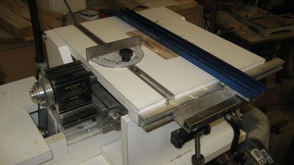
Jay To remove the table, loosen the two knobs that lock the module to the rear T- track; pivot the table up so it clears the saw, the slide the module to the right. Then, remove the arbour. Everything off in less than a minute. Putting back on is just the reverse. No adjustments needed. Bruce -
On the Hermione web site a book in English is now listed. Cost is 19 EU. http://www.hermione.com/en/shop/books-dvds/94-book-la-fayette-s-liberty-ship-of-1780-english-version.html The only description is "A synthesis of the Hermione's reconstruction." Has anyone seen a review or detailed list of contents?
-
I recently got a small (Taig) lathe, so I built a base for it and the motor, along with some drawers for keeping the accessories out of the dust. I also wanted a small table saw, but with the lathe I already had a powered shaft, so why not mount a circular saw on it and then a table. For simplicity, the table height adjustment uses the same tilting concept as used for thickness sanders. This is where I started and the attached pdf describes the design and how I turned a lathe into a table saw (pun intended). When time permits, I intend to also build a thickness sander based on the same concept. Bruce TableSaw.pdf
-
Re-hardening Brass
lehmann replied to Landlocked123's topic in Metal Work, Soldering and Metal Fittings
Copper and copper alloys, such as brass, can only be hardened by work hardening. This is usually done by running a sheet between rollers, or it can be done by drawing (pulling a wire through a hole smaller than the diameter of the wire). Hardening can also be done by beating with a hammer, but the results will be uneven, to say nothing of the resulting uneven thickness. At some point the material becomes brittle, which may limit the amount of bending possible for your part. In a rolling plant, the sheets get hard after a few rolls, and so, they need to be heated (tempered) to soften them so the thickness can be reduced some more. Iron, is also hardenable by working, but the amount is limited. Hardening cannot be achieved by heating and quenching (rapid cooling) unless the carbon content is greater than 0.12%. This limit basically defines the difference between iron and steel. To go beyond this, other elements are added, creating alloys. On the topic of alloys, brass is an alloy of copper and zinc; bronze, is an alloy of copper with tin, phosphorus, aluminum, nickle or silicon. Aluminum can also be hardened, but this is mostly done by precipitation or solution hardening, where the material is kept at a certain temperature for period of time. The hardness is designated by a "T" code, as in 6061-T4, which is the most common grade of aluminum. We work in brass and copper in models because they are easy to work, easy to solder or braze, and are corrosion resistant. We could use stainless steels (there are many grades), but they tend to be quite hard, as anyone who has tried to drill and tap a 4-40 thread in stainless knows. Aluminum has some of the same properties of brass, but it's very hard to join, although I've seen some aluminum "solders'. Although aluminum is corrosion resistant, it does form a soft oxide layer that comes off easily. Probably more than you wanted to know, but now that it's been emptied from my brain, I have room to learn something else....- 2 replies
-
- 16
-
-
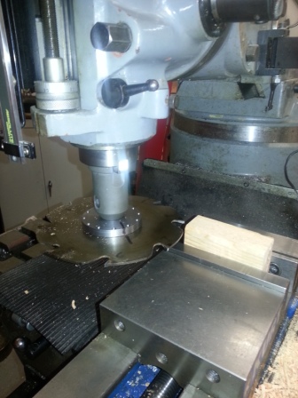
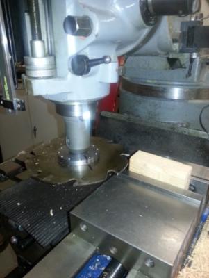
I just saw the picture in the first post. By coincidence, I have the same setup on my mill, but it's on a full size knee mill, not a table-top. I do research for the sawmill industry on saws, and this setup will be used in an experiment I'm doing. To give some scale, the saw is 7.25 inches diameter. I also use it for woodworking - it's a great overhead router, although the spindle speed is a bit low. Like it for woodworking, because I don't have to build templates to do repeated or precise slots, holes, etc. On the other end of the scale, I have the "sensitive drill chuck" for drilling a #80 hole. One of the nice things about having full size machines is that I can build the table-top machines myself. Hopefully, later this week I'll share some pics of a small table saw that fits on a Taig lathe.
-
DelftShip ship design software
lehmann replied to lehmann's topic in CAD and 3D Modelling/Drafting Plans with Software
I stand corrected (and educated). Which way was your little toe pointing? I did try importing offsets that were created by the program - actually one of their sample models - and it didn't work too well, which why I recommended the tracing option. Bruce -
DelftShip ship design software
lehmann replied to lehmann's topic in CAD and 3D Modelling/Drafting Plans with Software
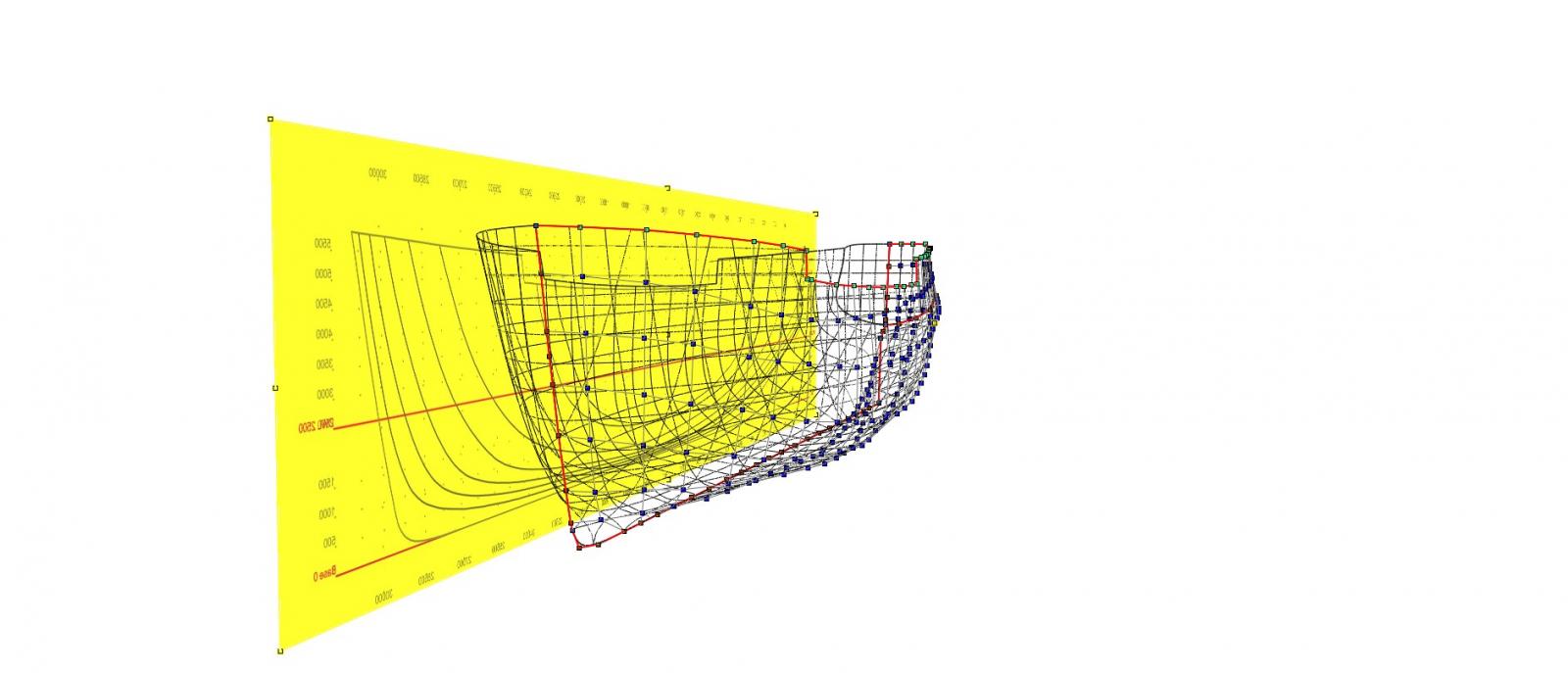
Larry, There are two ways to import a set of lines: One, is to create a table of offsets. The second is to trace the lines from a scan. To do this DelftShip has the option to put a scanned image in the background. I think this was just to make a pretty picture, by, for instance, putting a picture of the lines behind the 3D model (see the picture below). However, I converted the pdf of the lines drawing of my frigate into a jpg, which DelftShip can import. What I ended up with is an overlay of the jpg image under the program's working set of lines. In this case, I just imported the profile and buttock lines. Have a look at the attached file. You'll see the working lines with the control grid that is used to control the hull shape. The scanned lines are in the background and slightly offset from the working lines so you can see them. I had to scale the scanned image a little, but the proportions were not distorted in the process. To start the process, you'll need to create the basic profile and the spacings of the sections, buttocks and waterlines to match the lines in scanned image. This will allow you to properly scale the image. The one limitation is that only one view of the lines can be imported, as I did, unless you want to import the all views in one image that you then drag it around depending on the view you're working on. Overall, this looks like a viable method for re-creating a set of lines. Bruce FrigateTracedProfile.pdf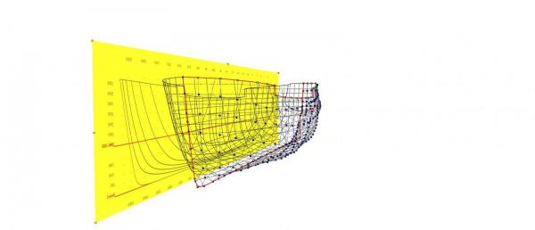
-
I've been playing with the free version of DelftShip (www.delftship.net) for creating hull designs. I've done quite a few designs by hand but I've never been able to see how I could create a faired hull with 2D CAD: it would be too cumbersome. As an test, I created a model of a 30 m "frigate". Although I didn't use all the tools for fairing the lines, it only took my about three hours to create this design. I found the tools for pushing and pulling the hull into shape reasonable intuitive. I've attached some of the output files: Lines drawing Table of waterline offsets (program can also output a point-cloud file) Hydrostatic data Resistance data - it looks like the hull speed is about 9 knots. Perspective renderings The program can also use a table of offsets to create a model. I didn't add decks, wales or ports, but the program is capable of this. I did manage to add the keel, masts and a bowsprit, however. I'm not sure the ship modeller will find this too useful, but there is an interesting feature for laying out the panels of the develop-able surfaces for chine boats. Those who research hull design, especially how it affects speed, cargo and armament capacity, and perhaps seaworthiness, could find it useful. I wonder how Chapelle's "Search for Speed Under Sail" would have benefited from being able to quickly do resistance analyses. If anyone wants the Delftship project file, please contact me: this forum won't all me to attach it. FrigateResistance.pdf FrigateHydroStatics2.pdf FrigateHydroStatics.pdf FrigatePerspective1.pdf FrigatePerspective2.pdf FrigateOffsets.txt FrigateLines.pdf
-
Seeking information on determining load waterline
lehmann replied to trippwj's topic in Nautical/Naval History
From some modern texts on the design of wooden boats: Sailing Yacht Design: by Douglas Philips-Bert: Weight Calculations. These are not often made for small craft, except when built to rated classes or of an uncommon breed on which there is little data. With larger craft weight approximations are sometimes necessary, and particularly so when no inside ballast, except a little for trimming purposes, is to be used. Indeed, if weight calculations were not so time consuming, it is doubtful if the praises of inside ballast would ever be sung so cheerfully. With wood construction, however, weights are always approximate owing to the uncertain density of timber, which varies by 20 percent or more depending on green and seasoned states. Weight calculations are to a large extent common sense and dreary arithmetic, palliated by the intelligent use of approximations. One of them is the cubic number. By its means the structural weight of yacht may be approximated from that of a similar yacht, of the same type of scantlings, but of any size. The cubic number may be accepted as: ( LOA x Max. beam x Depth of hull) 100 the later quantity excluding the fin keel, and being measured to point of greatest body depth. The structural weights vary in different yachts in the same proportion as their cubic numbers. [Detailed calculations] Planking: Area multiplied by the thickness... Frames and Timbers: The area of the frames will be a certain proportion of that of the planking, the proportion depending on the siding and spacing of the frames. .... Keel, Stem, Sternpost and Deadwood: Approximations are best made when dealing with these members, since their irregular shapes make the calculations of volume difficult. Stringers, Gunwales, Shelves and Clamps: The length of these may be measured from the drawings.... Deck: The area is most simply measured with a planimeter... Deck Beams: The siding and spacing of the beams show what proportion they bear to the deck area....Allowances must be made for heavy beams [at masts or hatches], and for hanging and lodging knees. Joiner Work and Furnishings: This may be worked out by proportions from similar craft. The only other method is to consider each item in turn. Skeen's Elements of Yacht Design: Rev. by Francis Kinney Comparative Weights To make a rough estimate of the weight of a new boat based on the know weight of an old boat multiply the weight of the old boat by the length of the new boat divided by the length of the old boat. ----------------------------------------------- If the ratios of draught/length and beam/length are similar for the old and new boat, then the two formulas give the same estimate. -
Seeking information on determining load waterline
lehmann replied to trippwj's topic in Nautical/Naval History
Replies in blue... There is also the question of what tolerance would have been acceptable or detected? Did ship owners require a performance test in terms of how much cargo could be stowed at an determined draught? Are there records of ship owners taking shipwrights to court? -
Seeking information on determining load waterline
lehmann replied to trippwj's topic in Nautical/Naval History
I'm from the camp of roach101761: LWL is a nice to have, easy to draw, but very difficult to predict. Even assuming the mathematics for determining displacement were used and measuring the area of cross-sections were accurate (having tried it, counting squares to measure areas is not that accurate, and the planimeter wasn't invented until 1814 and not readily available until at least 1854 [Wikipedia: planimeter]) there is the other side of the equation: estimating weights and the distribution of weight (center of gravity). I've designed a few small boats and the practical problem of estimating the weights of all the parts of even a 14 ft dingy is intimidating. Specifying the location of the lead fin keel for a modern yacht is downright scary. For a wooden ship, each piece has an irregular shape that is custom fitted to the preceding framework, so there are no drawings to base calculations. I think modern ship builders can do this because they use 3D solid modelling and the steel plates, gussets, etc are laser cut. Even then, major components are still weighed. Furthermore, with wood, what is the moisture content? The planking swells considerably after the hull is put in the water, so even if you weight each fitted plank just before attaching it to the frames, your numbers are suspect. Another issue you need to consider is, as I understand it, that early design drawings were to the inside of the planking so that the builder can use them for directly laying out the frames. My impression is that creating line drawings to the outside of the planking is a relatively new concept, which, I would assume, coincided with the development or acceptance of mathematical methods, which need the external shape. This, of course, wouldn't apply to lines taken off existing hulls. Given the large uncertainty in the as-built weight and weight distribution of a large wooden vessel, I suggest that the only method of prediction is how a hull of similar form and construction floated. Tradition isn't just from a lack of knowledge or an aversion to risk (or ridicule): staying close to successful designs allows builders to build. The historian of engineering, Henry Petroski, has written extensively on the benefits and risks of the trial-and-error development. Since all ships carry a significant weight of cargo, the final water line for profitability, stability or best sailing trim is determined by the ship's officers. Hull shapes or construction methods that couldn't do their job likely became evolutionary dead-ends. In this sense, an interesting study would be to compare, with modern naval architectural tools for displacement, stability and seaworthiness, the design of hulls which were widely used to those that were only built once. I suspect this happened quite often as construction technology with steel created more design options, which justified the cost of naval architects and marine engineers. Lastly, I wonder if there were intermediate stages between the initial drawing and the final construction that could be used to empirically determine where a ship will float. Half-hull models could be used to determine displacement; and builder's models could help with center of gravity. As a research engineer, I like having a prototype to test new features for unintended consequences and to verify my estimates. PS. I just checked the drawings in Chapman's Architectura Navalis Mercatoria (ANM). (1768) The lines are all to the inside of the planking. I also see that Chapman, in Treatise on Shipbuilding, shows the calculation method for a ship's load curves (draft vs displacement). The curves for many if not all the of the drawings are show in Plates XXIII and XXIX of ANM.. The calculation looks like it's based on Simpson's Rule using the areas of each water line, although I'd have to verify this as the multipliers aren't quite what I would expect. Also, quadrature methods of numerical integration were know before Simpson derived that general formula that is attributed to him. Kepler used it long before that, so in German, its known as Keplersche Fassregel. -
More engineering calculations: Based on the data in http://www.thenrg.org/resources/articles/The%20carronade.pdf, the muzzle velocity of a 32 lb carronade is 750 ft/sec. Assuming that the explosive force, and therefore the acceleration, is constant, then the average muzzle force is 70,000 lbs. A lot of this force will go to accelerating the mass of the barrel, but for the moment assume all of this force has to be counter-acted by the elevation screw (which would happen is the slide stuck, or the breech rope were too long and the fighting pin hits the end of the slot). From the geometry of the 1812 design I described above, then the load on the elevation screw is about 25,500 lbs. The drawings specify a root diameter of the screw as 1.25" (outside diameter = 2.125"), resulting in a stress of 20,000 psi. The yield strength of wrought iron is in the range of 23,000 to 32,000 psi. It they used a heat treatable (hardenable) or cold worked steel, which was available, the the yield strength is in the 60,000 psi range. Since I've greatly over-estimated the load, a screw could survive with a good safety margin in "regular" use. Bruce