

lehmann
-
Posts
129 -
Joined
-
Last visited
Content Type
Profiles
Forums
Gallery
Events
Everything posted by lehmann
-
One observation that has been missed is that the width of the strips is equal to the vertical distance between the ratlines. Or, more precisely stated, the distance between the knots. As long as you can set the strips level, there is no need to use a paper grid.
-
 Yellow cedar is actually a cypress (Chamaecyparis nootkatensis). However, while cypress is usually associated with shrubs, yellow cedar trees can be huge. http://vancouverislandbigtrees.blogspot.ca/2013/05/worlds-largest-yellow-cedars.html You could probably build a model out of one branch. (There's a few growing down the street and I keep my eye open after wind storms) These trees can produce large clear timbers and boards. It's also hard and rot resistant. As a result it is a very good material for ship building, especially planking. I've done carving in yellow cedar and it is hard and fine grained, so it holds details very well, and has no pores, as hardwoods have. Fairly uniform in color, but may get mineral streaks. It is dense, similar to black walnut, so expect your finger tips to get sore when carving. The grain is generally straight, but can get some swirling. Can have a quite pungent smell, as are most cypresses and junipers (Tennessee red cedar is actually a juniper). Overall, a yellow cedar should be a very good wood for model shipbuilding. Actually, it's the only wood I've seen that can be used on full size and well as model ships. Many years ago I stored away a large box of yellow cedar cuttings, and some 2x4's that showed up in a load of Douglas fir boards, with the intention of using it for a plank on frame model. If I need more, a few local sawmills cut it and it is stocked locally. Prices for good grade boards are similar to hardwoods, such as red oak.
- 71 replies
-
- 10
-

-
However, a recessed edge on a carrot has been rabbited. (old cabinet maker joke).
-
I just go a notice from Seaforth/Pen&Sword publishing that the latest Trafalgar Chronicle yearbook of the 1805 Club (http://www.1805club.org/)has been released. http://www.pen-and-sword.co.uk/The-Trafalgar-Chronicle/p/12463?utm_source=seaforthpublishing.com&utm_medium=subsite
-
Lee Valley (Veritas) not only makes tools, but they also have a large collection of old tools. This rope maker from 1880 showed up in their recent newsletter. http://www.leevalley.com/en/newsletters/Woodworking/2114//collection.htm Those of you in the US mid west may want to start hunting in the antique shops.
-
John, Anything is possible. Not sure if this is a good idea though. I haven't worked with a wobble saw, but unless there's some special grinding of the top of the teeth it won't produce a flat bottom on the dado. The smaller the diameter of the saw relative to the kerf, the more pronounced the rounding will be. (To produce a flat bottom, the saw kerf would have to be zero.) Secondly, does the motor on the Dremel saw have enough torque to plow a dado? On your math, a 1/8" wedge in say a 1" diameter washer and a 4" diameter saw will produce an approximately 1/2" + kerf wide dado. Not sure why you want to make dados on the Dremel. Not much need for wide dados in model ship building. If you're making grating, then generally you have to use jeweler's saws anyway. If you want to do dados for cabinet work, but don't want to spend the money on a stacked set, then just do multiple kerf cuts. I do this on my 10" Delta when I don't want to take the time to set up a dado blade.
-
I had a look at the practicum and the pictures certainly imply there's lots of material. However, I suggest making the templates to see what they tell you.
-
As is now, the choice between iron and bronze is based on a trade-off between costs and corrosion resistance (life). However, if the corrosion can be controlled, then iron would probably the the best choice. I'm not sure what grade of iron would have been used, so I can't say there would be a strength advantage for either metal. Bolts were used extensively in the keel and skeg - anywhere where the larger timbers needed to be connected. Not sure of building practice in early 1700's but, later, bolts were used to hold the clamps to the frames. Also, they were not bolts as we know them, with a thread on the end(s) for a nut. The fastening was a clinch ring (washer) or plate put over the end of the "bolt" and then the end was clenched (flared over), so they are more like rivets than bolts. In a sense, a treenail is a wooden rivet. Bolts that come out the bottom of the keel are covered with a shoe board. Other places for bolts that would be exposed on the exterior would be the channel iron fastenings, and other anchor points for rigging.
-
scarf joints
lehmann replied to dennistestagrossa's topic in Building, Framing, Planking and plating a ships hull and deck
I posted some instructions for making close fitting joints at http://modelshipworld.com/index.php/topic/11685-how-to-get-close-fitting-connections/#entry357279. I agree with Capt. Chaos, you need to use a scoring knife to layout joints accurately, especially for scaled work. Even for cabinet scale woodworking (dovetails, tenons, etc), I use a scoring knife to layout the joints to ensure a tight fit. To use an Aubreyism, pencils ain't in it. -
soldering iron or torch? advice please
lehmann replied to Mark Pearse's topic in Metal Work, Soldering and Metal Fittings
For a part that big (mass) you'll need a very large soldering iron to get the metal hot enough to allow a good bond for solder. Large irons don't lend we to small parts, so this is therefore probably a job for a torch. However, with either solder or brazing rod, you'll have to set up a jig to hold the flanges to the tube while you're heating it because this job will have to be done in one go, or, as you say, if you try one joint at a time, the others will slip off. One alternative is a micro-torch, which has a small, hot flame, but you have to be quick before the heat gets to the other flanges. And, they're not cheap and work best on a hot fuel like oxy-acetylene. Even with a micro-torch, I'd set up a jig. Nice sketch, and I which I were working on such a large scale. -
I agree with Druxey - - Wales are uniform width planks-they don't taper towards the ends, which is what is on the drawing. However, since the distance from the deck to the bottom of the gun ports should be somewhat constant, the edge of the deck should be parallel to line along the bottom of the ports. On the other hand, the lower edge of the wales should be below the deck line so they can be tied to the deck knees.
-
Arbortech Power chisel
lehmann replied to John Allen's topic in Modeling tools and Workshop Equipment
John I'm not sure that a power carver will make you a better carver. I have a Ryobi DC500. I haven't used it for fine work - mostly for hogging material so far, but now I'm curious to see how it works for fine work. I hear it's discontinued, but I see several on eBay for around $100. The Arbortech looks like it was designed for building log houses or carving grizzly bears out of a stump. Another option, if you have the Foredom rotary shaft tools - they have a power chisel hand-piece H50 - $80, including six chisels. ($56 on eBay - how does that work?) On the topic of chisels, it looks like there is a standard for the tangs and how they fit into the hand-piece. I've heard that FlexCut makes an after-market set with quality steel. -
Maybe I'm just romantic, but what ever happened to prison hulks?
-
The book Specialize Joinery, by Corkhill and Duckworth ( http://woodcentral.com/books/specialized_joinery.shtml) has a section on ship's carpentry that shows a construction detail of a sliding door similar to the picture. Based on the design, I doubt the door is water tight, and unlikely to be totally wind-tight either, but would be good for keeping spray out of a deck house. The book authors note that sliding doors are better than hinged doors as they do not bet caught by the wind and are less likely to hit things (people) or be hit. I have a copy of the book. It was formerly available from Lee Valley, but is not in their current catalog. This is a reprint from the 1920's so there may be scanned copies of the original somewhere on-line. Amazon and Abe Books have listings.
- 11 replies
-
- 1
-
-
- 19th century
- Galilee
- (and 6 more)
-
Matt, I also have a large mill, (clone of a Bridgeport knee mill) with digital readouts. I also use it for wood, mainly as a overhead router when I don't want to make a router template. For small work, I'm contemplating building a mount for a rotary tool (Dremel, Proxon, die-grinder, etc) so I can use their high speed for small diameter cutters and engravers. Basically, I would build a plate with a split-hole for clamping to the quill and the rotary tool would be offset from the quill by 4 or 6 inches.
-
I'll add an observation or three: An 18th Century model of the Victory does not show these features, nor does it include the swivel guns. From an on-line search of how the Victory is currently configured, it is as in the model: there are hammock-nettings above the rail. http://collections.rmg.co.uk/collections/objects/66473.html http://www.hms-victory.com/things-to-see/quarter-deck The "feature" appears to have an opening at the top, which implies that this is an opening for a rope. There are four of these, and the three swivel guns are between them. Could they be cleats for securing the guns - there should be something to keep them from spinning. However, I wouldn't think something that big would be needed. I had look through McGowan's book on the Victory. It shows the Turner drawing (pg 26) and a note that it is inaccurate in that Turner drew rope wooldings on the mizzen mast, but it is know that steel bands were put on in 1803. Also, when I look at the fore and aft sails (pg 156) it looks like the mizzen stay sail is sheeted on the end of the poop deck. The sheet tackle is shown in a bit more detail on page 188. I assume that McGowan's drawings are for how the Victory is currently configured, so may have been different in 1805. One final though, is there a possibility that the stay sail sheet tackle and the swivel guns would have interfered with each other, and the mystery feature is a method to avoid that? I've also looked in McKay's and Longridges's books, as well as a Google search, and I didn't see anything about swivel guns. The swivel guns, however, also show up in West's 1806 painting of the Death of Nelson. https://en.wikipedia.org/wiki/The_Death_of_Nelson_(West_painting). Some details in this painting are known to be inaccurate: some people shown were not actually there. I couldn't determine if West visited the Victory, or whether he had access to Turner's drawings. There are other paintings that show the railing, some with the buckets in front of the rail. It appears that Turner's drawing and West's painting are the only places the swivel guns show up. Also, the only place the mystery feature shows up is in Turner's drawing. This implies that two are possibly linked. An alternative is that Turner drew in the swivel guns based on the configuration of another ship. Are there any records of swivels being added or removed? Lastly, in Turner's painting, the railing has been "removed". Is this from battle damage, which wouldn't be consistent with Turner's sketch, or did Turner just remove the railing so there would be an unobstructed view of Nelson? I think he may have also "removed" the mizzen mast. Have I helped, or just added confusion?
-
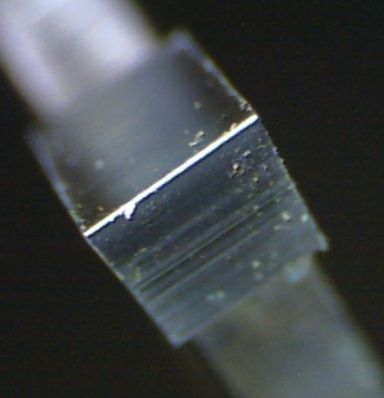
As a follow-up on my comments about dull tools, the attached picture clearly shows the reflection of the rounded edge of this very dull carbide saw tip. For a "nearly sharp" tool there will still be a line, but it will be much narrower and can only be seen if the angle of the light is just right and maybe only through a jeweler's loop.
-
Kurt, Small work requires small SHARP tools. Chisels generally refer to carpentry, cabinet making or sculpting, which are all meant for working larger pieces. Micro-carving tools are available, but they aren't useful for model ship joinery. I recommend using the common Exacto or scalple knives. Straight "chisel"shapes as well as gouges are available that are inexpensive but they are sharp. Small joinery is mainly done with something like a # 11 Knife guided by a steel straight edge, otherwise the knife follows the grain too easily. Like all joinery, make the cut surface square to the main surface, otherwise the joint will have a gap. If you can't do this with a knife, use a sanding stick or a file. As others have mentioned, sharpening is a good skill to develop. For Exacto and scalples I use a 1000 grit stone followed by a leather strop. Even if you throw away the blade, you need to determine when the edge is dull. A dull edge is round, and if the light is at the right angle, you can see a line of light reflecting off the rounded edge. Another method for testing sharpness is to try slicing the edge of a piece of paper. A sharp edge will slice of a 1/16 strip: a dull edge will not cut or plow.
-
Seeking information on determining load waterline
lehmann replied to trippwj's topic in Nautical/Naval History
At one time, not so far back, "calculator" was not a device, but a profession. -
Rope Making Basics
lehmann replied to mikiek's topic in Rope Making/Ropewalks's Discussions about Rope Making
Have you considered using wire? McMaster Carr sells copper wire down to 0.003" -
Seeking information on determining load waterline
lehmann replied to trippwj's topic in Nautical/Naval History
How did they balance all of these, in the absence of slide rules, spreadsheets and calculators? Welcome to the risky world of engineering and architecture. The capabilties of theories and math only go so far and at some point judgement is needed. This still applies in the age of super-computers. Remember that with more knowledge we want to take advantage of it. It also means we soon realise there are more unknowns to deal with. However, decisions have to be made. Some universities teach "design" which try to systematize the process, but these methods usally come up short because the methods of weighting the various factors are too linear. In reality, each design that gets built is an experiment. This point cannot be over-emphasized. Some succeed and some fail, but hopefully someting is always learned. The trick is to know how much the new theories can be "stretched" and still be valid in an untested condition, at which point the system breaks down and a new or modified theory is needed. Too many successes lead to over-confidence in the theory, which often leads to dramatic failures. If you're interested, an engineering professor named Henry Petrosky has documented this through a history of engineering failures. The basic truth is that we learn through failure, not success, because successes don't unusally get near the limits that define a theory. For example, Seppings wouldn't have created diagonal bracing unless previous builders hadn't pushed the limits of ship length to the point where premature hogging occured. Going further, Seppings' method would sooner later have reached its limits and failures would start to appear. However, builders switched to steel construction..... Or, to tie this this back to where it started, judgement comes from experience- experience comes from poor judgement. -
A little heat will increase the drying rate. A few (incandescent) light bulbs will do. Lean your table top against the wall to form a tent and put a lamp or two inside. By the way, apply a coat to the bottom of the table top to limit moisture getting in or out to fast that could cause the plank to warp. I'll throw in the classic concoction I use for work bench tops and furniture that will see some use. 1:1:1 mix of linseed oil, mineral spirits and varnish. I suspect you can substitute tung oil for the linseed oil. It penetrates deep, is somewhat hard, but the surface is not smooth or glossy. It does create a slight amber tint though. Since oil-based varnishes are getting hard to find, I tried a water based version for my last batch. It worked well and doesn't seem to separate in the can.
-
Seeking information on determining load waterline
lehmann replied to trippwj's topic in Nautical/Naval History
The estimation of load water line and tonnage (displacement or cargo capacity) is just that - an estimation to as a check on the designer's intention that the vessel could fulfill its role. Nowadays, we understand the physics, the mathematics have been simplified (even without the aid of computers to do the repetitive number crunching), and we have accurate measurements to prove everything. At the time there were many unknowns and uncertainties, but the the designer still needs some assurance he can be proud of the design, or at the least, not be sued. These various formulas are nothing more than first approximations that included some basic factors that were easy to measure mixed with a few fudge factors that make the numbers fit with "experience" or a consensus of opinion. The ease of measurement is important in that different people would get the same results and those who didn't have access to more sophisticated measurement tools were not left at a disadvantage. As an engineer, I still do a "back of the envelope" calculation like this as a reality check of a computer model analysis. You may not realize that some rules in standards, such as the National Building Code, are still based on a consensus of experts when the theoretical and experimental data does not provide sufficient information. The fudge factors would, I assume, vary depending on region, or predominant ship design. Factors that "work" for shallow draft coastal boats don't work for deep water clipper ships. However, customs and insurance officials like to have a common formula that can be easily and uniformly applied by their inspectors. The question arises, who chooses which rule to use? Ship owners pick the lowest when charged for customs and insurance, and the highest when impressing a customer. The same is done now in all aspects of business, even if standards organizations are tasked with choosing an evaluation method: there are always factions trying to influence the choice. It also reminds me of the rating formulas for racing yachts, which resulted in some strange looking boats. I recall reading somewhere that tonnage rules also produced some un-seaworthy distortions as owners found hull shapes that maximized actual cargo capacity relative to the rated tonnage. As with all business performance measures, there will always be someone who "games" the formula, resulting in an unintended consequence. My conclusion is that tonnage rules are a different animal than displacement calculations for load waterline or trim. The tonnage rules have a strong connection to politics and influence. On the performance side, it may be possible with computational fluid dynamics programs to choose the best displacement and trim for best sailing qualities, but I doubt anyone has figured out the hull design that is the best compromise for all sea conditions, cargoes and sail trim: maybe the designers of the America's Cup boats get the closest to this ideal. Even with computer models, there are still several model ship testing basins used for experimental validation. There is still a lot of evolution in ship design and that the key to evolution is survival - physical and economic. The main difference between 2016 and 1816 is that designers have the tools to avoid the failures. I'm not sure a modern designer, forced to work with wood and hemp, could design a better ship than their predecessors developed by trial and (lots of) error. -
Tools and Supplies for My "Shipyard"
lehmann replied to daveward's topic in Modeling tools and Workshop Equipment
Take a trip to the local version of the Dollar Store: Wooden clothes pins: regular size and small (<1 inch). They work well as clamps and can be modified to whatever shape you need. Metal bull clips Elastic bands - for clamping Small C-clamps Dowels, other strips of wood. Actually, pretty good quality. If nothing else, they make good handles for custom tools. Tooth picks Wire and nails - not model quality, but good for making jigs, bending patterns, or as clamps Paints - Not sure if I'd use them on a model, but I'm using the cheap acrylic to practice air-brushing Paint brushes - good for cleaning up chips. You may find some that are actually good for painting Pins, needles, threaders, crochet hooks, tweezers (probably need to file the points) Storage containers - all sorts for small parts and tools Card board and foam board for making templates and light duty jigs Alcohol, Q-tips and cotton swaps for wiping up School geometry set - for protractor and 45 and 30/60 triangles. ( A GOOD set of dividers are useful for transferring sizes form drawings to parts ) Pliers/cutters - may work for you, but cheap enough that you can modify the ends if needed for other shapes. Glues - may find a brand name you can trust to last for the long life of a model. Other stuff ok for jigs, etc. Tape There are also many things you can make: Bench hook - could double as a shooting board (for plane or sanding block) Rigging tools (hooks, pushers, etc) V Block bench extension (for scroll saw work) Since you WILL want more tools ( just admit it now, we understand), make a wish list and buy them when they come up on sale. MicroMark and Model Shipways frequently have deep sales. For further items: Soldering iron - for making metal fittings and for bending planks (it's heat that allows wood to bend easier, not moisture) Small bench vice - preferably with a rotating head. (like Pana-vice, but there are much less expensive versions available) Third-hand with magnifier Dental picks Looping pliers Jeweler's saw Lastly, a comfortable chair! -
In general, all files work for metal or wood. However, very coarse files, such as rasps, are not useful for metal because if the bit at all they would require a lot of force to push. Rasps, are used for removing a lot of wood fast, but the surface will be rough, as in relatively deep gouges, or badly torn up is cutting across the grain. Very fine toothed files tend to clog up when cutting soft metals such as brass and aluminum: an old trick is to rub some chalk into the file before working. It also helps to reduce friction. For filing small metal parts, you'll need a fine tooth file, otherwise it will "catch" if there are only one or two teeth cutting. I find that the diamond coated files work well for these situations - they are more like sandpaper than files. Inexpensive sets can be found that will last long time unless you want to work in hard metals.