lehmann
-
Posts
129 -
Joined
-
Last visited
Content Type
Profiles
Forums
Gallery
Events
Everything posted by lehmann
-
Oscillating Wonder Cutter
lehmann replied to Jim Rogers's topic in Modeling tools and Workshop Equipment
This principle of this knife is the "slicing effect". The most common example is cutting a tomato - if you push the knife straight in, it won't cut, but if you add a movement to the knife 90 degrees to the direction you want to go (add a slicing action), then the cutting forces are greatly reduced. The amount that the forces are reduced depends on the speed of the slicing movement relative to the pushing speed. The faster the knife moves, the lower the forces. The effect has nothing to do with the material properties, it's just geometry in that the slicing movement reduces the sharpness angle of the knife, as seen by the material being cut. There is a limit to how much the slicing speed will reduce the forces because there is friction and for an oscillating knife, which has to stop at both ends of the stroke so the full forces are needed to push the knife forward. The quoted 40,000 rpm is probably way more than needed. If you want to try a home-made version, attach a knife to the working end of a beard trimmer, electric hair clipper or an electric engraver. I suspect one of the main design problems with the Wonder-cutter is balancing it to avoid the fingers going numb and to provide better control. I've made a bigger version using a sharpened scraper on an oscillating multi-tool (Fein, for example). I was able to slice off 1/8 inch thick pieces with a roughly 80% reduction in cutting force. -
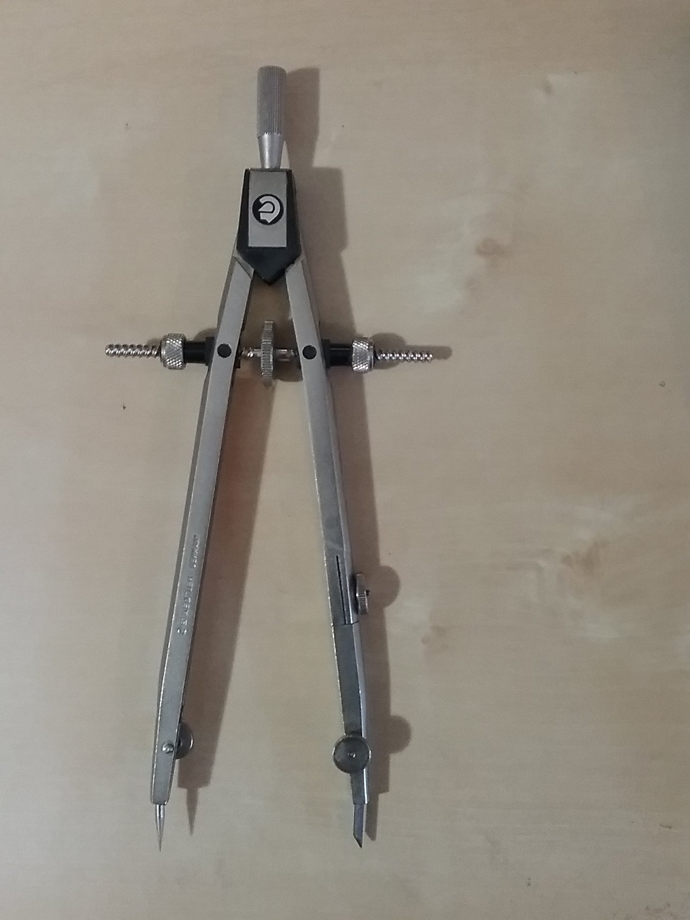
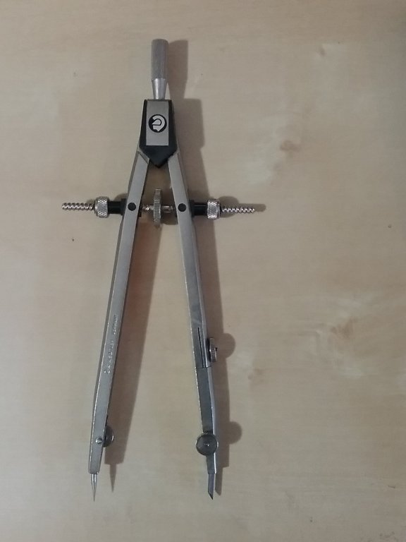
The above advice to use professional drafting compasses is the best option. Best compass I own: Made my living with it many years back and still use it. Made by Staedtler, but I don't see anything similar on their web page. A few on eBay though. The double start thread allows fast adjustments by just pulling on the arms, but the thread is fine enough for accurate setting. The ferule on the nut jams it tight, stopping any movement.
-
Anyone using electric plank bender?
lehmann replied to MESSIS's topic in Modeling tools and Workshop Equipment
These heat benders are nothing more than a standard 30 or 40 watt soldering iron with the tip cut off and a brass disk pressed on to the end. Actually, the soldering tip could be left on. Very simple to make and even simpler if the the soldering iron can hold different tips, as with the Weller models. I also have a wood burning iron that takes different screw-on tips: it wouldn't be difficult to make a large tip. -
Just for interest, on a scaled basis: $0.20 fitting at 1:96 scale -> 1:1 price would be $0.20 x 96 x 96 x 96 = $177,000.
-
Reducing extractor noise
lehmann replied to Williamo's topic in Modeling tools and Workshop Equipment
Several years ago I built a sound reducing box for a compressor to be used at trade shows. I used the best rated sound absorbing rigid foam and batting I could find, but the main way sound escapes is through vents needed to feed air to the compressor (with a vacuum, the air has to get out) and other cracks. I ended up building a box with a double bottom so that the sound had to go through a bit of a zig-zag maze, somewhat like a Dorade vent. The double bottom also reduced the transmission of mechanical vibration. The maze was filled with batting, and the air inlet, made up of many small holes, faced the floor. Other than those holes, the box was sealed. Fortunately, for this application, the compressor didn't run often, so I didn't have to worry about heat from the compressor. Since a vacuum doesn't generate much heat, this shouldn't be a problem. Avoid large, flat panels, unless they are very rigid. If it vibrates, it is basically a large surface to excite the air, just like the sound board of a guitar. Use foam, especially egg-crate foam, or batting on the inside surfaces to absorb (damp) sound and avoid reflections off of hard surfaces. To some extent, a soft covering on the outside panels also helps to deaden sound. That's one of the reasons the inside of cars are carpeted or are covered with a hard foam (the other reason being to reduce injury in a crash). As a last though, I wonder if putting a long hose on the air exit of the vacuum would help to contain the noise.- 17 replies
-
- 3
-

-
- cyclone
- vacuum cleaner
- (and 2 more)
-
Best Spindle Sander for Ship Modelling
lehmann replied to whaynes's topic in Modeling tools and Workshop Equipment
Grizzly tools has a small oscillating sander for hand or bench use. I was thinking of making a thickness sander with it. Seems to be well made (not a toy). Reasonable price and doesn't take up much space. Grizzly Tools;Oscillating-Spindle-Sander/T27961 -
Have a look at http://www.joliebrisemodels.co.uk/tenth/calculator.html, I shows how the camber shape is generated. The same shape is used for all beams, with the drop to the shear line being measured from the center of the beam.
-
You definitely need to straighten the hull before adding stringers or clamps. Adding them as is would lock in the shape. Since the frames are still above the shear line, you can put, on the outside of the frames, a heavy temporary pre-bent strake, or a sawn mold. As Druxey suggested, another possibility is to build external "shoring", something like is done in a dry-dock. The external support would bend the hull back, but still give you access to the inside. Good luck.
- 8 replies
-
- 2
-
-
- deformation
- ribs
- (and 1 more)
-
I like the belt type sanding sticks. For instance, Lee Valley sanding stick. MicroMark also sells them. Belts are a little pricey, but I find that I mostly use the tip, so I just keep moving the belt. They are rigid, easy to control, have a fairy find end to get into tight areas and they are narrow enough to see what you're working on. I use them for tapering and beveling planks - I don't even try to use a plane or knife.
- 12 replies
-
- 2
-
-
- sanding sticks
- files
- (and 1 more)
-
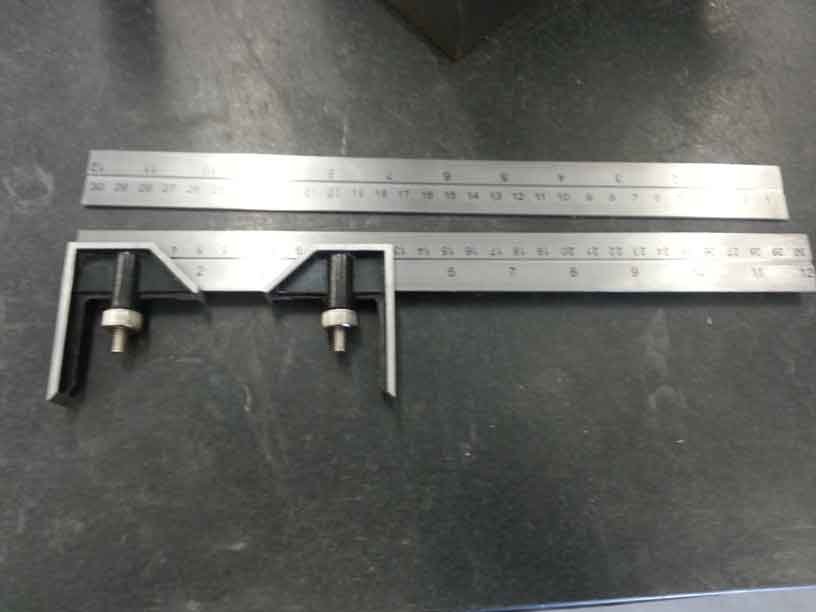
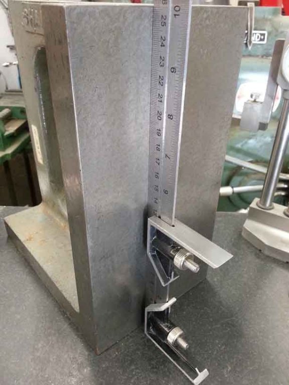
I was planning to make a set of wooded calipers/height gauge following Ed Tosti's design. However, I was at a local tool store that had metal squares on sale for $6 and I got the idea to use two of these to make the calipers. The result is shown in the attached pictures. Very solid, perfectly square (after a little tweaking), it has a built-in ruler, and I got an second ruler out of it. While I did file a sharp point to the end of the caliper, the metal is pretty soft (aluminum or zinc). If I need to do serious scribing, I'll attach a small knife.
-
Help reading plan
lehmann replied to Rick01's topic in Building, Framing, Planking and plating a ships hull and deck
I agree with Don Robinson - a steep pipe, probably through the water way. The feature you show on the deck is aft of the windlass, which certainly won't work. I know the replica of the Nonsuch has a windlass, so I tried to find a photo. The best I found was at https://photo-bytes.com/308-down-below. Unfortunately, the entrance of the hawser on deck is not shown. There is also a picture below-decks in the fo'c's'le, but no evidence of a pipe. Keep in mind that the Nonsuch was almost 200 years earlier than your ship. -
Don, I think the bigger problem is what you had in your first post - how to bend plywood in two directions. Plywood only likes to bend in one direction. I think one-piece decks only work for short decks, not where the deck runs the entire length. I see two options: Rip the false deck in to narrow strips, perhaps about 10 mm wide. You'll lose some material, ending up with gaps and there will be a bit of a kink at the joints, but that can be sanded down and covered by the final planking. You could also add filler strips. This has the added benefit that you don't have to fit the whole deck at once, and you can get some clamps under the deck beams. With a little bit of planning, you can make the first strip near the rail fit between the "ribs". Make some kerf-cuts on the underside of the false deck. This may give it enough flexibility to bend in two directions. However, I don't have much hope for this idea. Option 1, seems best to me: it will allow you to fair the height of the deck beams as you go, if needed.
-
Framing Math
lehmann replied to vwmiller's topic in Building, Framing, Planking and plating a ships hull and deck
For examples of computer generated hulls, have a look at the CAD & 3D forum. The most recent post shows exactly what you're thinking about. Pandora 3D Even with good modelling software, this is a difficult and time consuming task. Further to Druxey's post, the starting point for ship builders was to lay out the frames was to use parts of circles. However, a planked hull is not composed of sections of cylinders or cones unless hard chines are used, as in plywood boats. I suspect that once the frames were up, the process of fairing the frames for planking involved heavy use of the adze and broad axe. -
Not that I want to spread alarm about breaking spars, but what you are worried about actually happened to the USS Constitution in 1997. https://ussconstitutionmuseum.org/2017/04/20/springtime-for-uss-constitution/. The moral of the story is don't expose your model to 70 mph winds and 2 ft of snow (or the equivalent in whatever scale you're working at)! On a more practical tone, going to a strong hardwood, such as maple, would be my first choice. However, straight grain is also a larger factor, so best to split the raw material for the rough blank rather than saw it. Any wood that is going to be subject to bending loads, such as chair backs, bows, etc, are made from split stock.
-
Overall, a good design. I was just think of something like this for semi-automating block production. One simple improvement would to add adjustable gibs on the dovetails slides. With wood construction you can expect to see tightness of the slides change with the relative humidity. I see that the rails of the dovetails are held down with counter-bored screws, so there is an ability to adjust the tightness, but this also creates a chance for them to slip. I would insert a 1/8" hardwood gib, held in and adjusted by two 1/4" bolts. This should eliminate a lot of frustration with chatter and unpredictable sizes. Second point when building: make sure the axis of the rotary tool is parallel in both planes to the Z axis slide. If this isn't done, then you'll be breaking drill bits, especially for the fine sizes. If the case of the rotary tool is round and concentric, then the method described in the article will be fine, but expect to do a little shimming to get if right on. As others have mentioned, other than the left hand threaded rod and nuts, there is nothing exotic here. You could use right hand threads, but if you're used to full sized milling machines, like I am, you'll end up going in the wrong direction and wrecking parts. If you're not used to full size machines, you have no muscle memory to over-ride and you'll be fine. What's needed next is the lathe, so you can make nice hand wheels...
- 13 replies
-
- 4
-
-
- dremel
- rotary tool
- (and 1 more)
-
In North America we have nitrocellulose lacquer, which is solvent based. Lacquers are fast drying, so the solvents are very strong (very volatile), so you will want to avoid it since you have asthma. Varnishes are technically resin and oil based, so there is no nitrocellulose in the mixture. Shellac flakes are dissolved in ethyl alcohol and heated to make it liquid. As Kurt mentioned, it can be purchased pre-mixed. Shellac is the basis for French polishing, so you may be able to find it following that path. It is also the traditional method for finishing musical instruments. As a simple alternative, try diluting white glue with water. Brush it on, let the mixture soak in for a few minutes and then wipe the excess off. The water will raise the grain, so sand after it dries.
-
Are your difficulties related to laying out or marking the ports, or from cutting them out? (or both?). I have found over the years that accurate marking is the key to good results and the best way to mark is with a knife, not a pencil. With a line scribed by a knife, you can carve, file, sand right to the line, and you'll end up with straight edges and sharp corners. The smaller the scale, the more critical this becomes.
-
Rikon 70-100 woodworking mini-lathe
lehmann replied to Haliburton's topic in Modeling tools and Workshop Equipment
The Taig lathe is easy and fast to change from metal to wood and vise versa. First, just slide off the tail-stock. The carriage for metal working and the tool rest mounts for woodworking just slide on/off on the dove-tail base. There is a wide range of speeds that can be quickly changed on the stepped pulley from the motor. The Taig web site lists 520-5200 rpm. The gibs on the metal working carriage can be set up quite tight without any sticking for the whole range of travel, so the setup is very rigid. As for the rigidity of the base, I used my circular saw setup to cut some nylon sheet a few weeks ago - a tough cut - but, even when the belt was slipping there was no vibration or chatter. Length of the bed is 15 inches, but the distance between centers is 9.75 inches. As for the reference to alchemy, the lathe cannot covert wood into metal, but it does transform base square stock to perfect rounds. -
Rikon 70-100 woodworking mini-lathe
lehmann replied to Haliburton's topic in Modeling tools and Workshop Equipment
I have the Taig lathe, with both metal and wood working accessories. With the vertical slide, it can do the work of a small milling machine. Very rigid, and vibration free. To make it a bit more easy to use, I've added a digital scale to the carriage travel. I've also built an saw arbor and table so it doubles as my circular saw http://modelshipworld.com/index.php/topic/11441-turning-a-lathe-into-a-table-saw/. I also have a large Delta woodworking lathe. While in theory it could be used for modelling work, you'll need to get a chuck for holding small pieces as it's not possible to work with a spur drive, even a tiny version, for small diameter work-pieces. -
Staggered wales
lehmann replied to Kurt Johnson's topic in Building, Framing, Planking and plating a ships hull and deck
It appears, based on the position of the one gun port and hawser hole relative to the other gun ports that there is a change in the elevation of the decks at the point. This is seen in the picture and the two drawings. Is the forecastle a "split level" relative to the decks in the waist? There could be some construction detail that ties this staggered wale to the deck shelf. Another question: is this really a wale, or just a plank (wale or not) painted black for aesthetic reasons? To my understanding, the wales are a set of planks, not a single line. Lastly, I not certain that wales are always continuous. I've studied a few plans that seem to show cuts for gun ports. -
I bought one on eBay. Good ones are not cheap, which is amazing considering the general demise of manual drafting and the availability of cheap digital calipers. However, after examining their construction, I can see why they're not cheap - if there are errors in certain lengths and positions then the scale settings will be off enough to be very exasperating. They are a very different animal from regular dividers. There are some plastic versions available - I have one of these as well, but I think they are more for artists to scale a picture rather than for drafting. The major limitation of mine is that the ratio is adjusted by moving the pivot to holes of fixed locations so that ratios of only 1:1, 1:2, 1:3 are possible. I use them fairly often, and not just for model building. As others have said, if you're working a kit boat, you won't need proportional dividers. But if you're mashing drawings from different scales, they're a real time saver. As a poor-man's option if you only have standard dividers, I've attached an example of a grid I use for a converting between 1:72 and 1:96. I used a CAD program, but you can make a satisfactorily accurate version by hand. 72_96Scale.pdf Set the dividers on the dimension on the 1:72 drawing Place the dividers on horizontal base line Pivot from the right point of the dividers Set the dividers to span up to the diagonal line The dividers are now at the distance needed for the 1:96 drawing
-
From the CD of data and drawings of the USS Constitution (available from http://store.ussconstitutionmuseum.org/collections/books-models-modeling). Plate size: 14 inch x 48 inch Number of plates: 3400, in 28 rows Number of nails per plate: 120 to 150 Weight each plate: 6 lbs Thickness, based on density of 0.324 lb/in3 = 0.0276 inches At a scale of 1:48, the model plate thickness "should" be 0.00057 inch. The thinnest copper sheet I've been able to find is 0.002 inch. I'm working at 1:96 scale, so my main conclusion is that overlapping the plates will create too large of a step ( , so I intend to cut the plates narrower and shorter by the amount of overlap and just place them side-by-side. This is probably why the strip method works so well. I was also thinking of cutting a shallow rebate in the planking so the step at the top of the coppering is not so noticeable, but then I realized that the thickness of the top-sides paint is probably thick enough to hide the step.
-
Wood has a low thermal expansion coefficient - meaning the size does not change much with temperature. However, the temperature of the air affects the amount of water vapor in the air (relative humidity), which will, over time, change the moisture content of wood. As a result, you may see changes in the size of the wood if you leave it in the garage at different temperatures. Cabinet makers have long know to store wood at the same moisture content as it will eventually be used. In most houses, that's about 6% - 8% moisture content. Since, it takes time for the moisture content of wood to change, the first thing to do is keep your wood supply in the house, not the garage. Second, if you can, keep the model in the house when you're not working on it. There may be another trick - over-dry the planks before putting them on the hull. As the planks come back to equilibrium moisture content, they will swell slightly, closing up the seams, just as planks on a real ship swell when the hull is put in the water. There was a comment earlier that this may cause the planking to buckle, but I doubt it. FYI, a version of this trick is used by chair-makers to securely hold the bent backs into the seat. The ends of the back are shaped slightly over-sized to the holes in the seat. The backs are then dried in a small oven, just heated by light bulbs, to perhaps 2% moisture content. With the slight shrinkage that occurs the ends now fit (snugly) into the holes, but when the moisture content comes back to 6%, the end is solidly locked in place. So, if you're too impatient to wait for the planks to dry, make a small oven above a light bulb (or perhaps a heat lamp or a halogen). The drying time would be pretty fast for pieces as thin as planking and you may get the added benefit of over-dried planks.
- 19 replies
-
- 3
-
-
- separation
- wood movement
- (and 1 more)
-
Also, commercial drawing machines flood the die with oil, which lubricates the hole and takes away heat. Even for hand drawing of metals, some oil, wax or grease is recommended to reduce wear of the holes and to reduce the required pulling force. This is, of course, messy if done by hand, so I can see how a drawing bench would be desirable.
-
Roger, They are available from Lee Valley.... http://www.leevalley.com/en/wood/page.aspx?p=32681&cat=1,50230. Now, $36 CDN, though. I have the set and they're very nice. I bought these instead of LV's miniature spoke shave.