KeithAug
-
Posts
3,986 -
Joined
-
Last visited
Content Type
Profiles
Forums
Gallery
Events
Everything posted by KeithAug
-
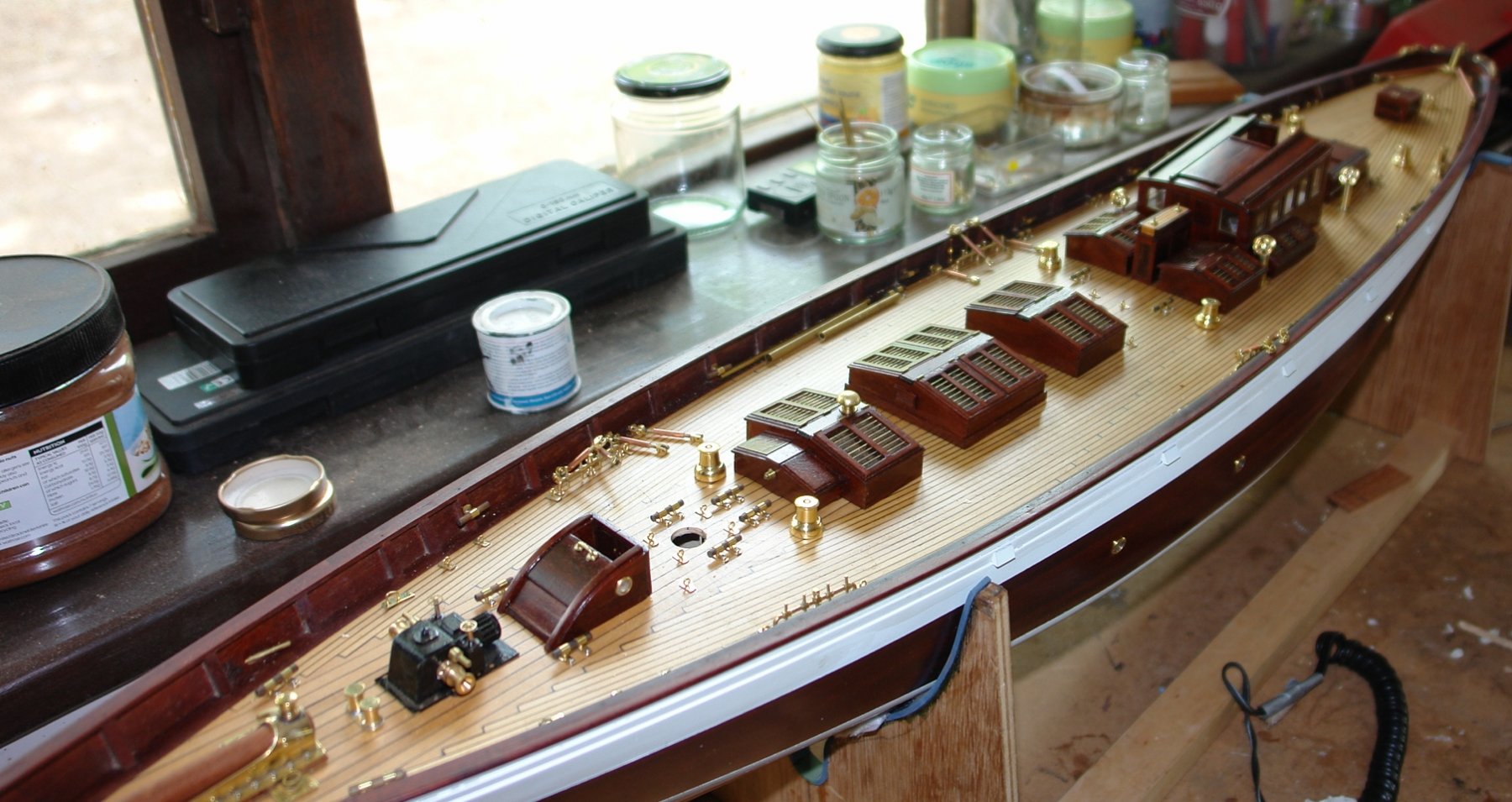
 Hello Dan - thank you for the kind words. The deck openings are for skylights which were made earlier (January). They just slot into the holes and sit well below the foresail boom.
-
Dan, wonderful description of the trials and tribulations of the model shipwrights. I loved the journey (and the result).
- 287 replies
-
- 5
-

-
- michelangelo
- ocean liner
- (and 1 more)
-
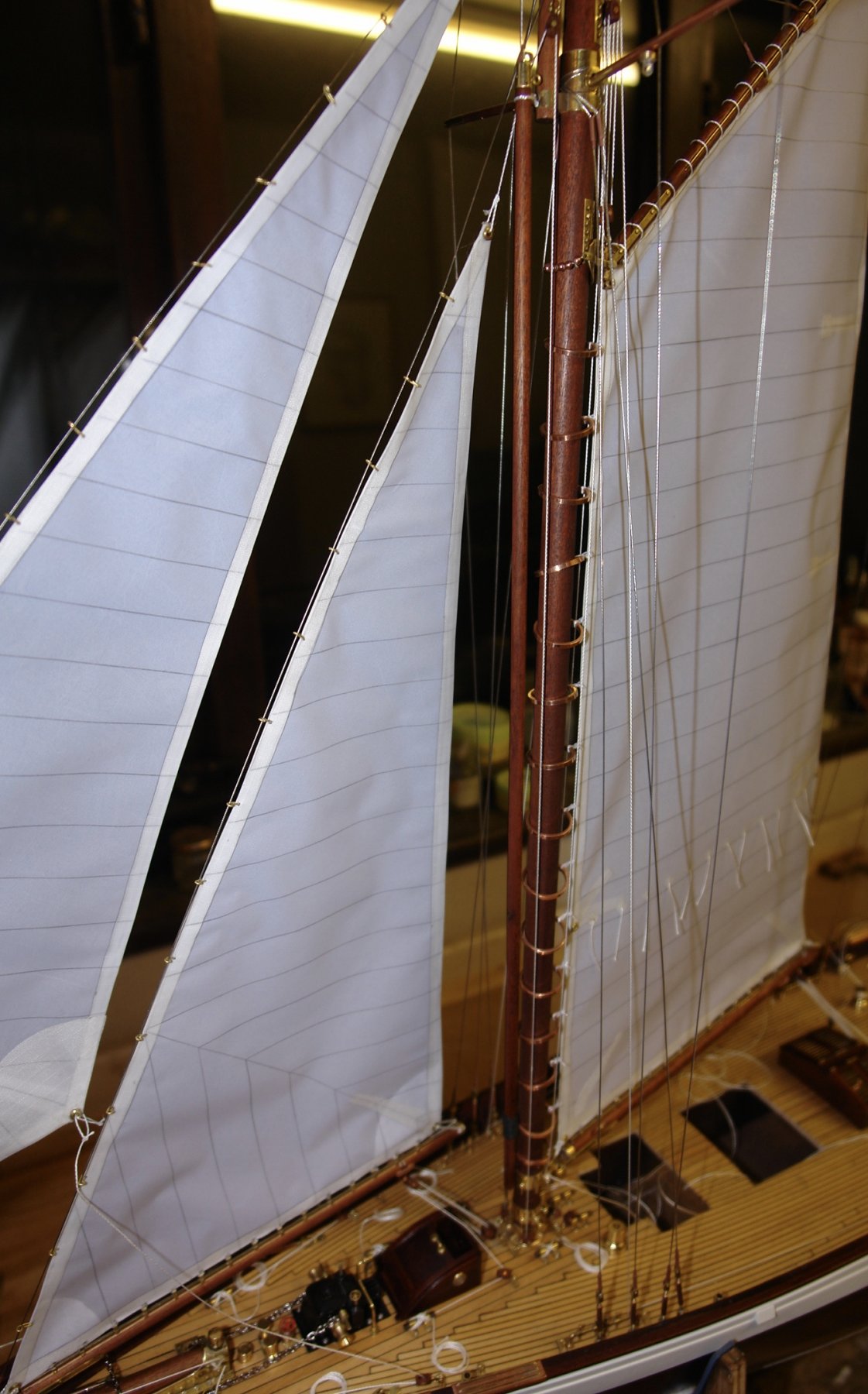
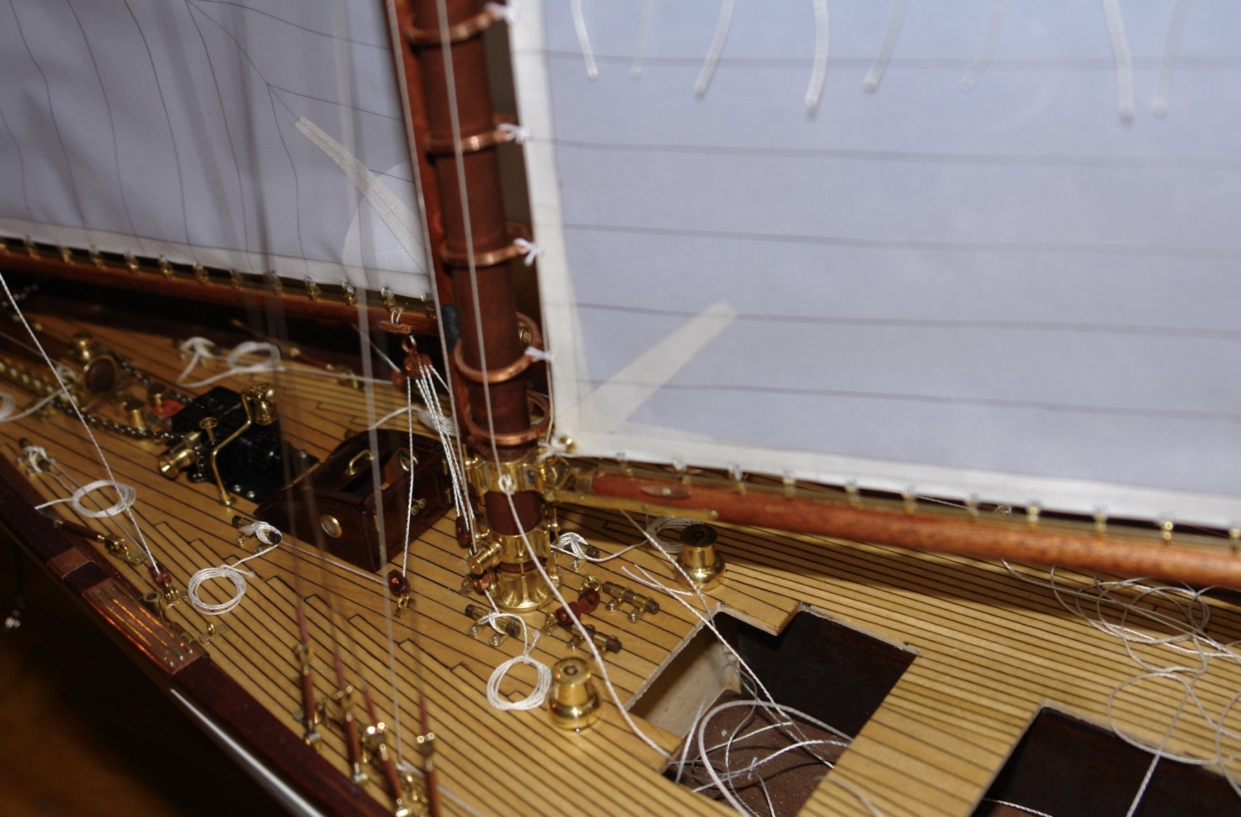
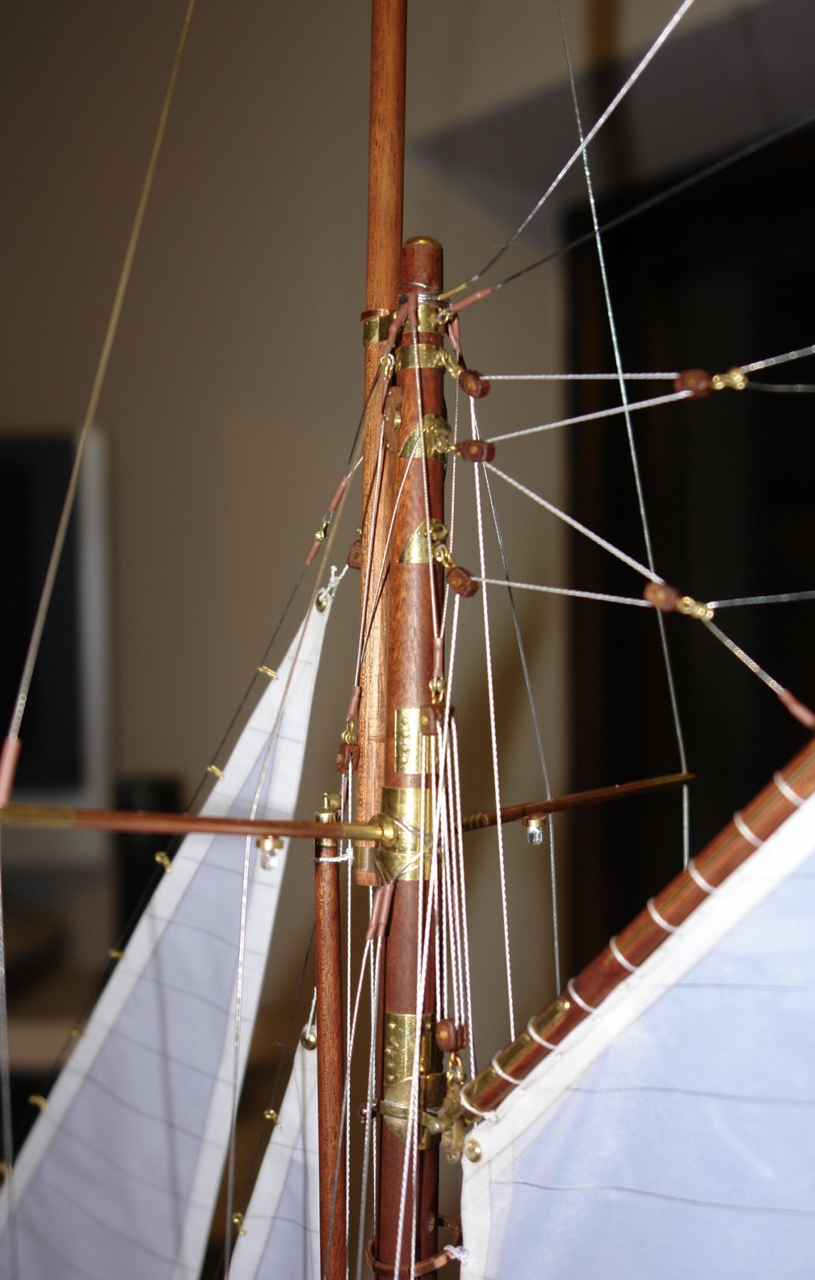
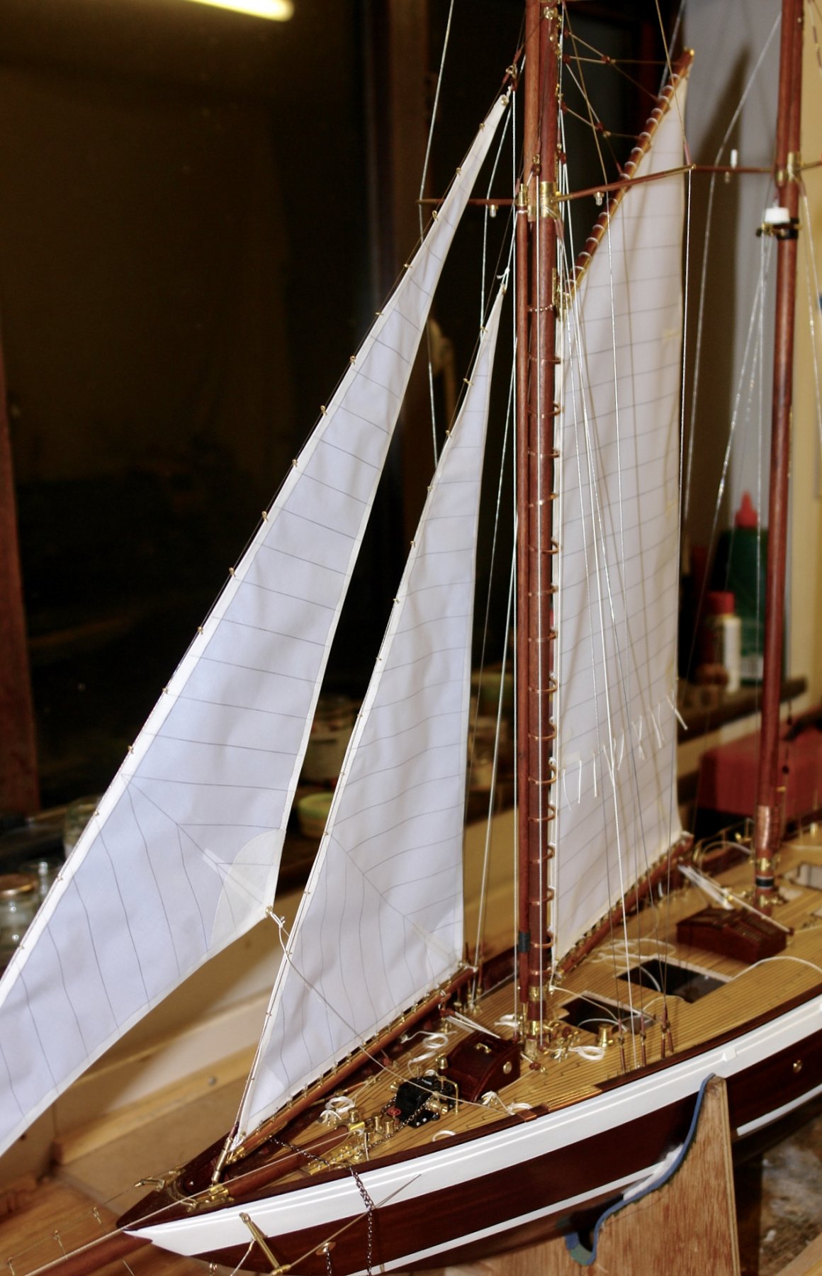
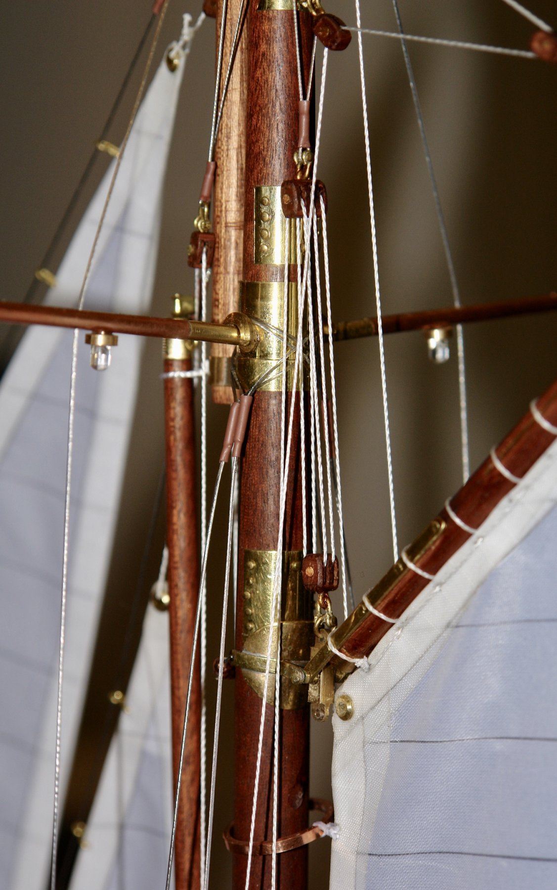
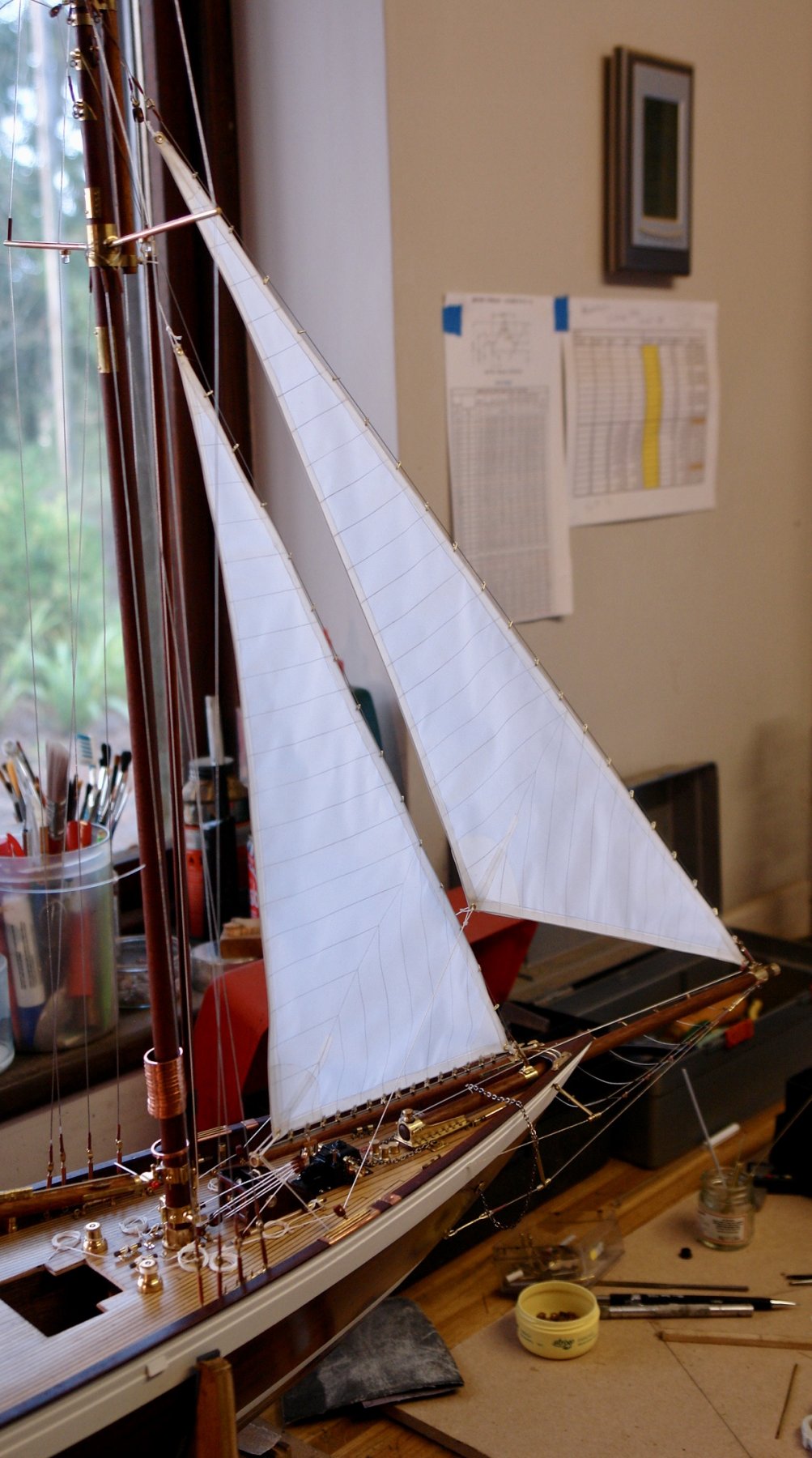
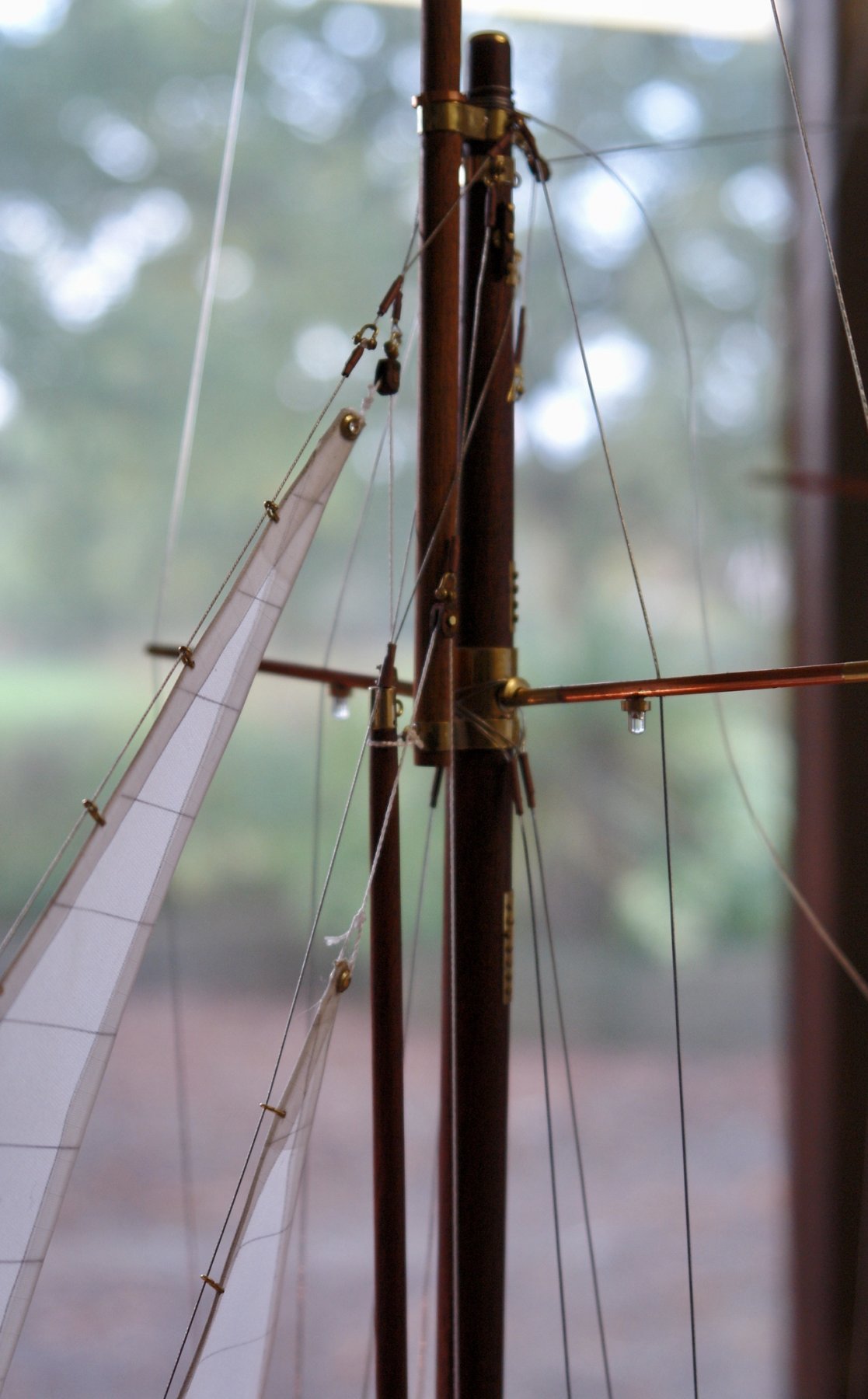
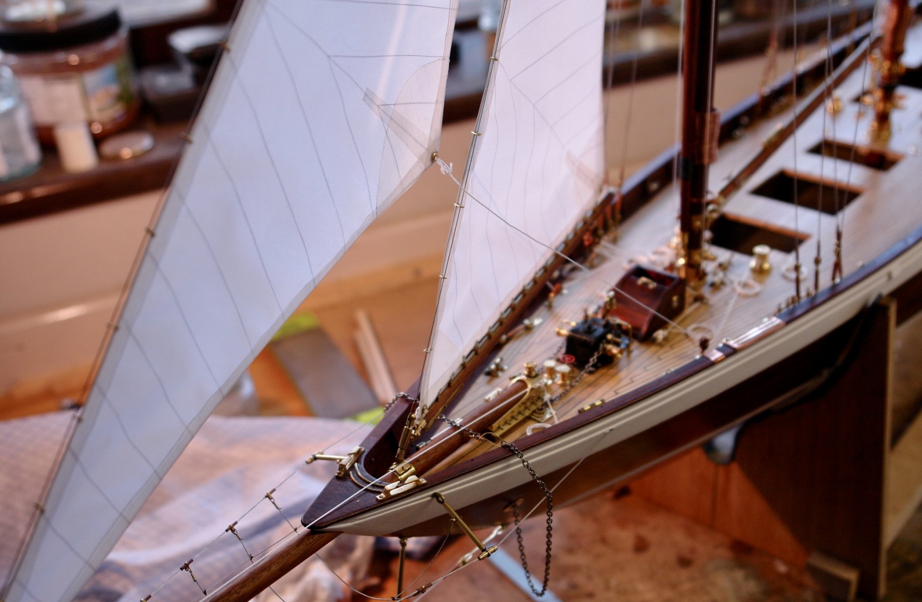
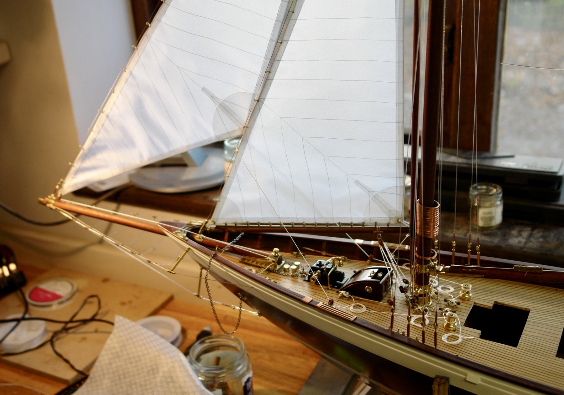
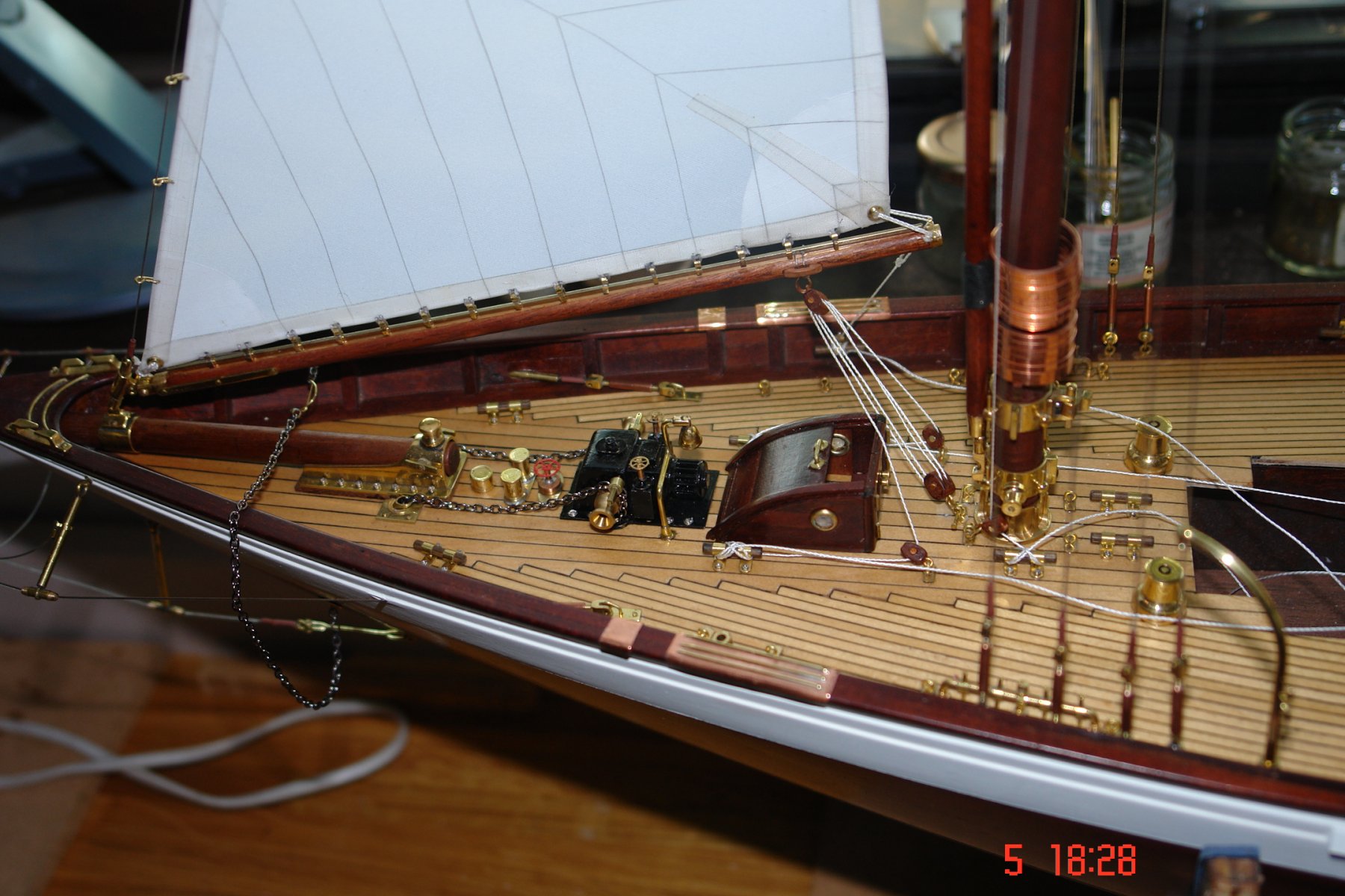
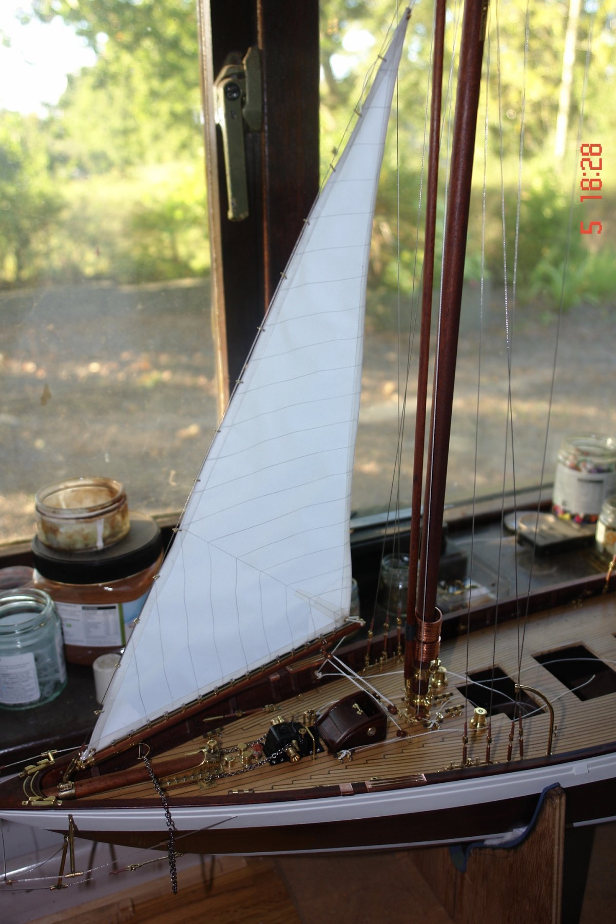
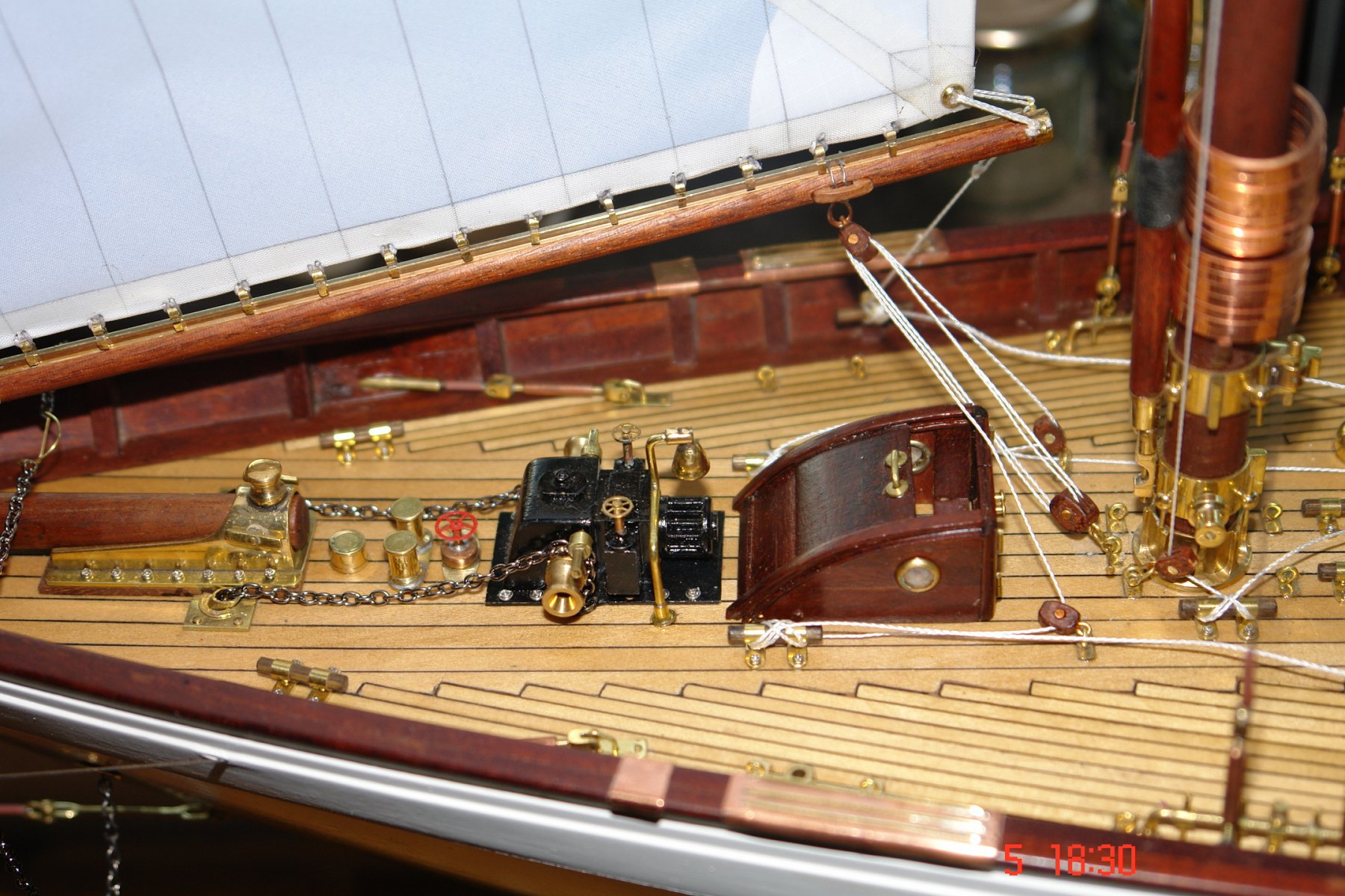
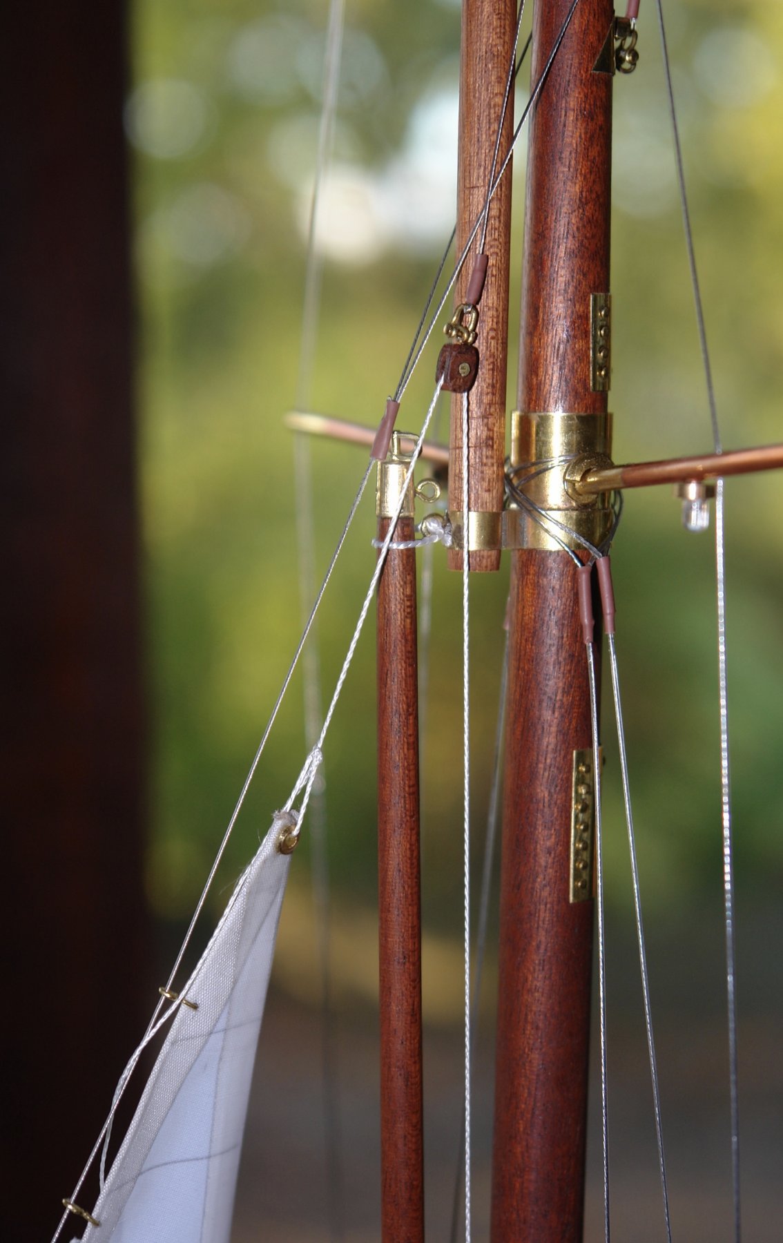
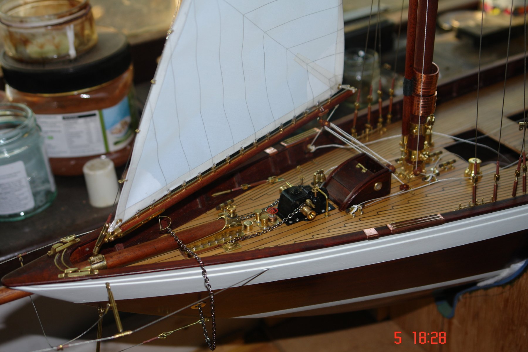
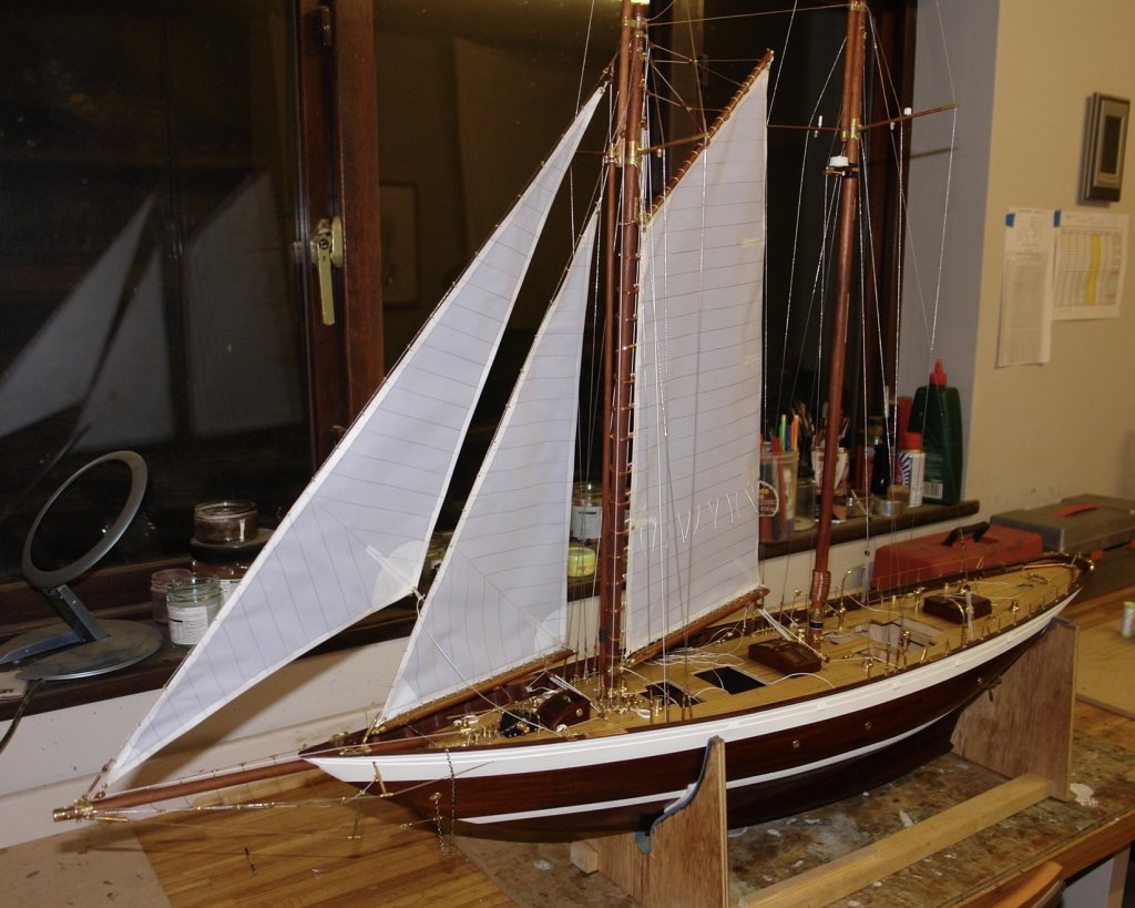
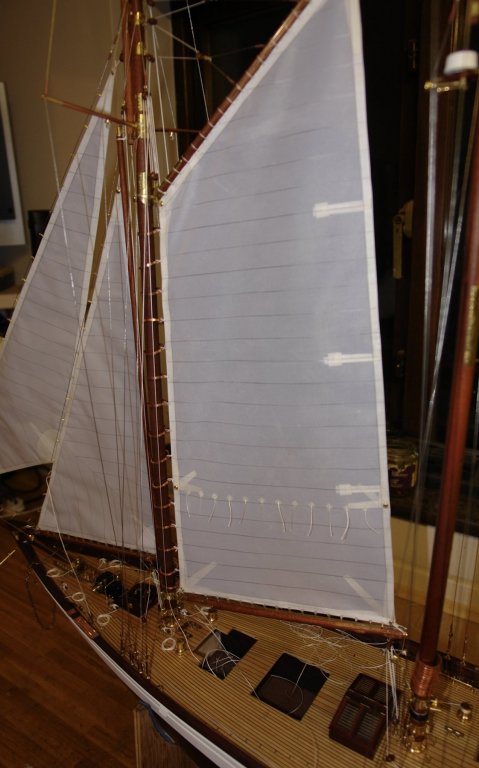
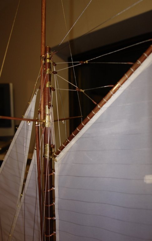
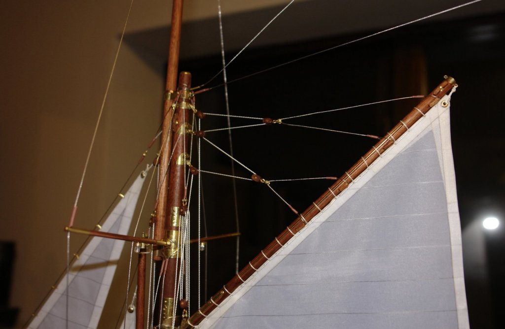
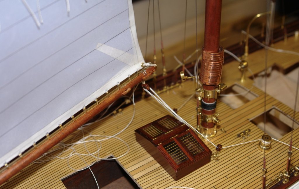
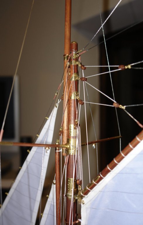
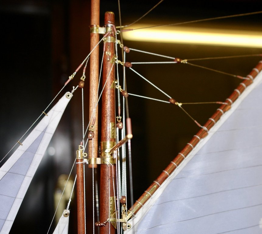
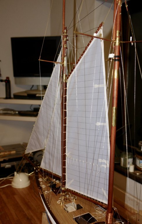
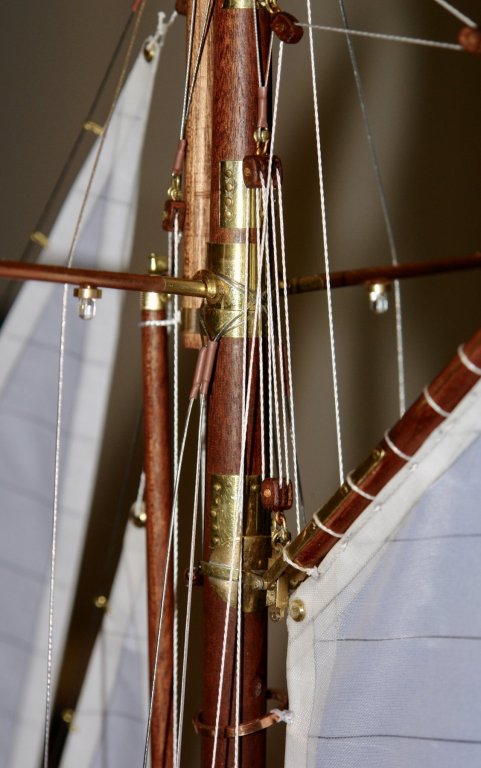
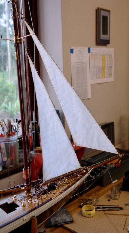
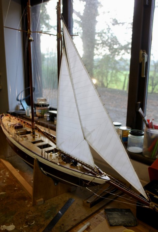
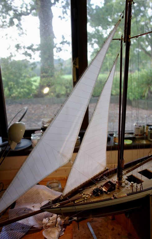
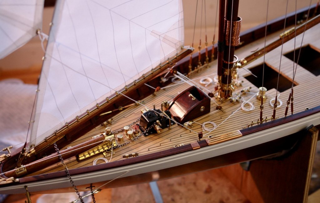
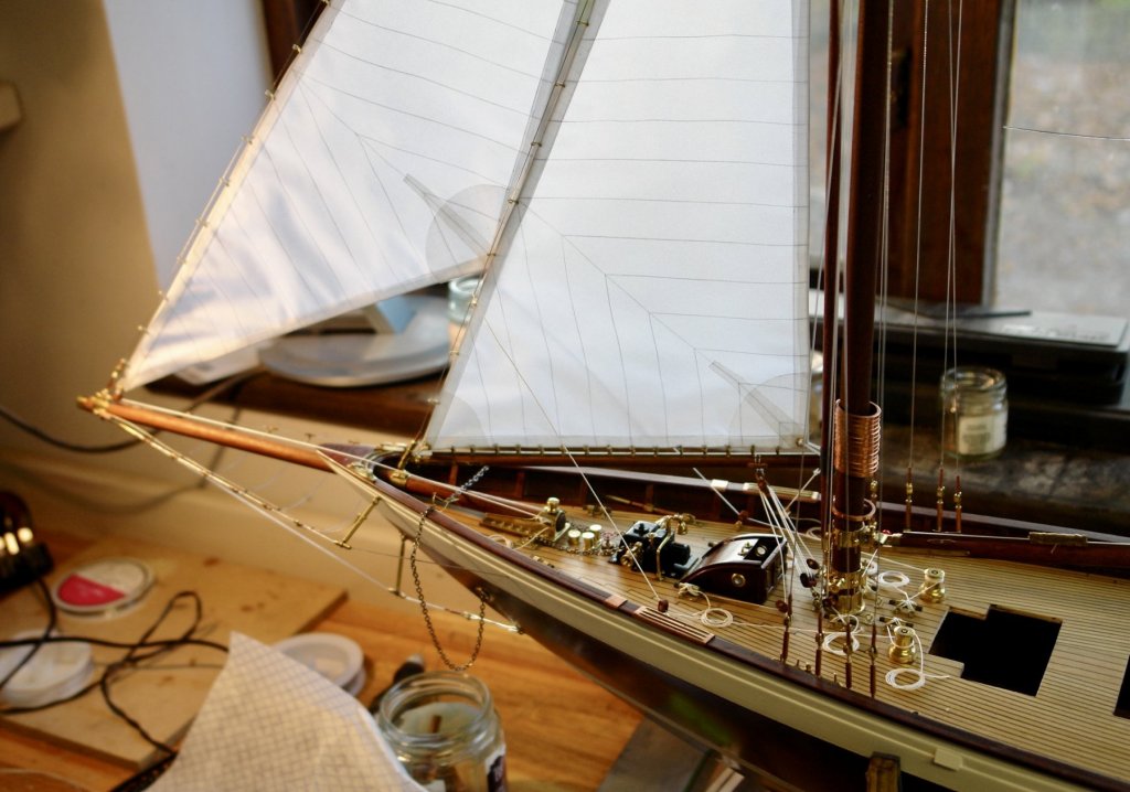
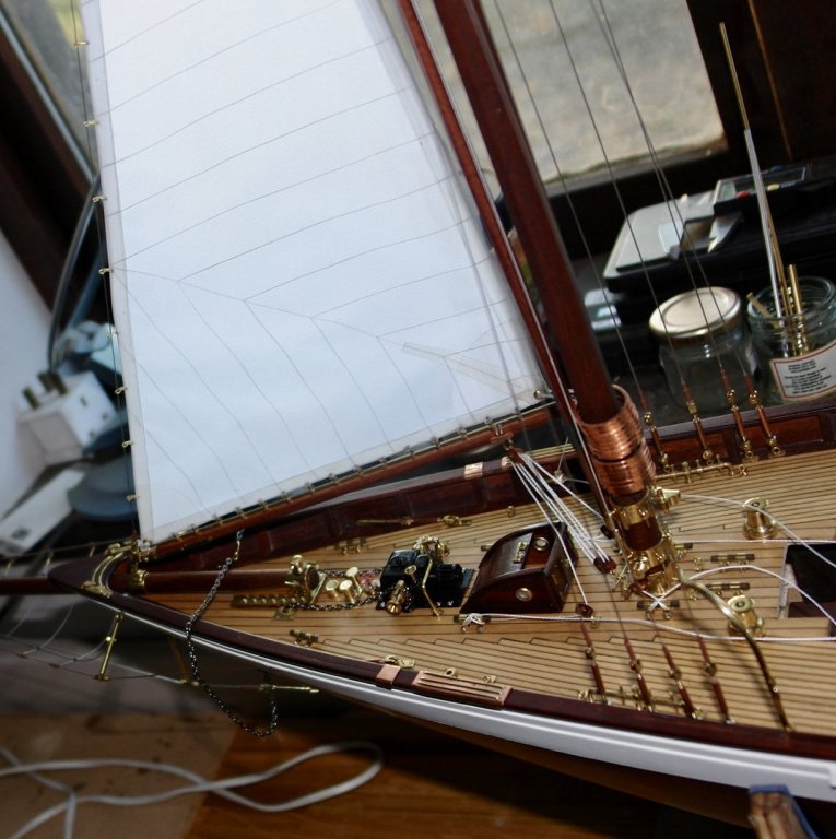
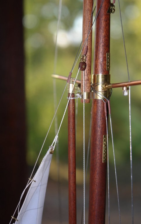
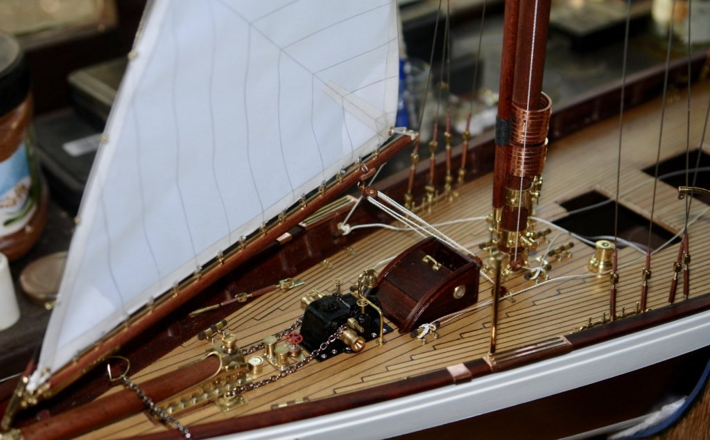
Thank you John and welcome back. I spent the last 2 days hoisting the foresail. In total the work on this sail has lasted 8 days with 3 to 4 hours spent working each day. I will try to describe some of the learning points and record what I will do different next time. The first few shots show general views. The main lines are in place but many other are still to be rigged. As I said previously the sail is about .250 short which means the saddle does not sit exactly over the mast rubbing plate. I think I can live with it. I tried to rig the gaff lift in situ but too many other lines got in the way. I took it off and rigged the blocks on the bench. Also in the following shot you can see the head of the sail is a bit full leading to the crease. I think I will be able to pull the crease out with a bit of extra lacing. I will cut the edges in this area back a little when I do the main. a The rigging of the peak halyard was likewise done on the bench. The 5 single blocks being threaded on to a single line before being offered up to the model. To pull the sail flat involved a fair amount of tension and i'm hoping that I don't wake up in the night to the twangs of parting lines or disintegrating blocks. I said in a previous post that the triatic stay was rigged in a way best suited to interfering with the peak halyard blocks. My fears were will founded and in the end I decided to re-rig it to what seems to be a much more sensible arrangement. The triatic is the line immediately above the top block in the photo below. Sewing the mast hoops to the sail in situ was a real pain. In the end I moved a lot of the halliards on to the beam to temporarily get them out of the way. Even then I ended up platting the thread around the wrong side of the stays on more than a handful of occasions. All a bit frustrating. I learned the lesson and so rigged the foresail sheets / blocks on the bench from the outset. A preventer is rigged to hold the sail over to starboard. A few other shots follow. Well thats it for a bit. As a penance for such an intensive period in the workshop I have to suffer visits to the extended family. So no more building for a week or so.


- 882 replies
-
- 18
-
-
Hi Nils The barrels look very good. How were they made?
- 692 replies
-
- 5
-
-
- eagle of algier
- chebec
- (and 2 more)
-
Hello Mike Adding photos should be quite easy. As you type your message at the bottom left hand side of the dialogue box is a paper clip and the words “click to choose files”. Click here and it will allow you to select the files on your computer which contain the images you want to post. Once selected they will upload and by clicking on them they can be imported into the dialogue box.
-
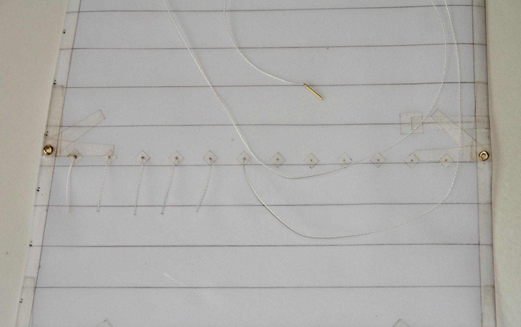
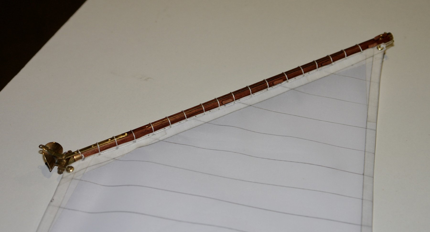
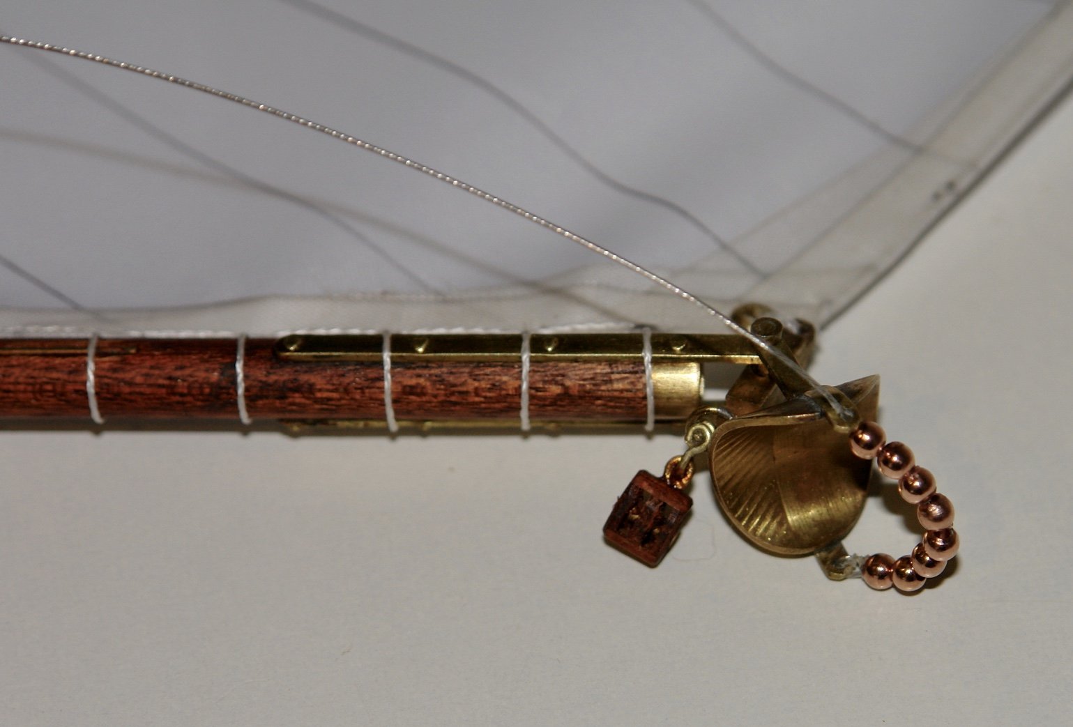
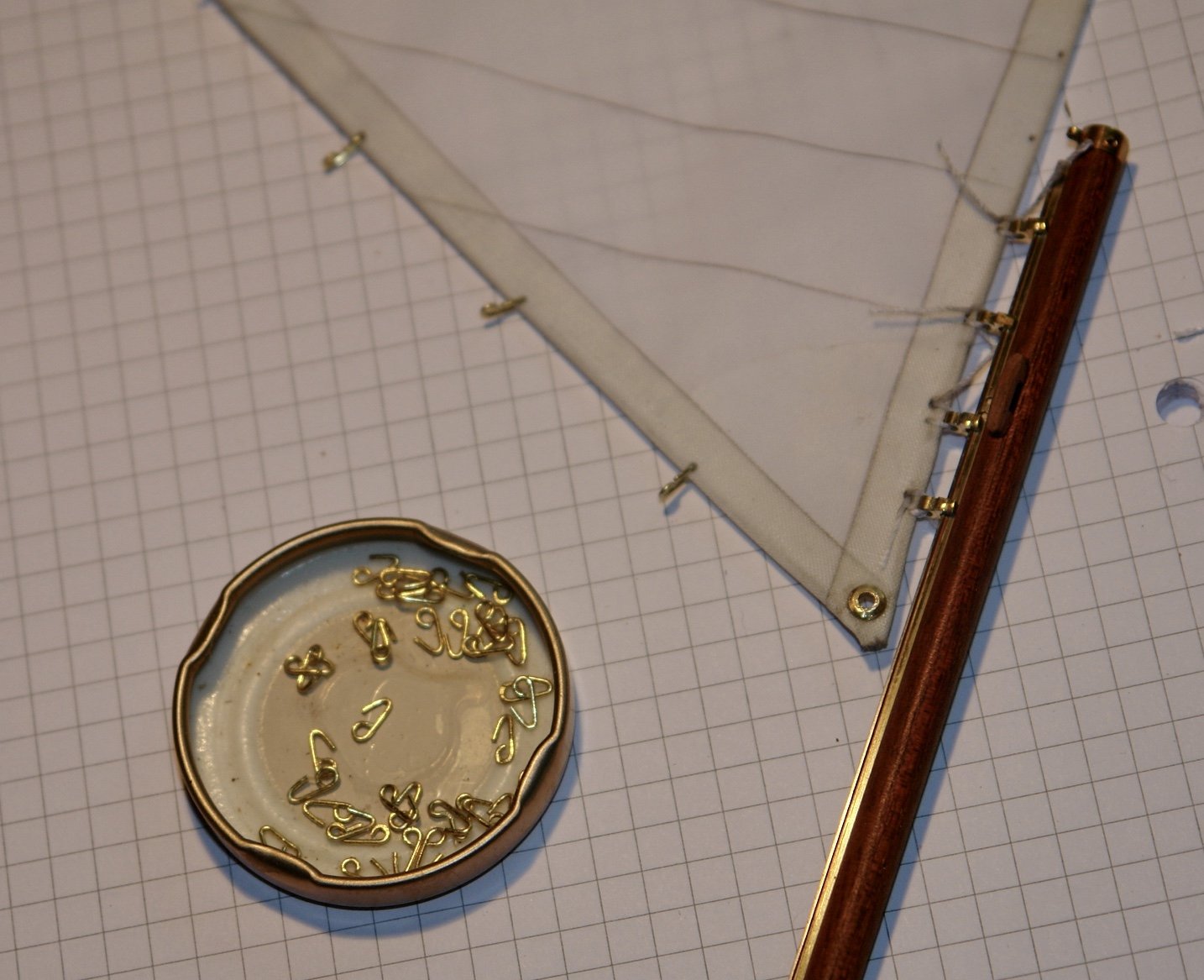
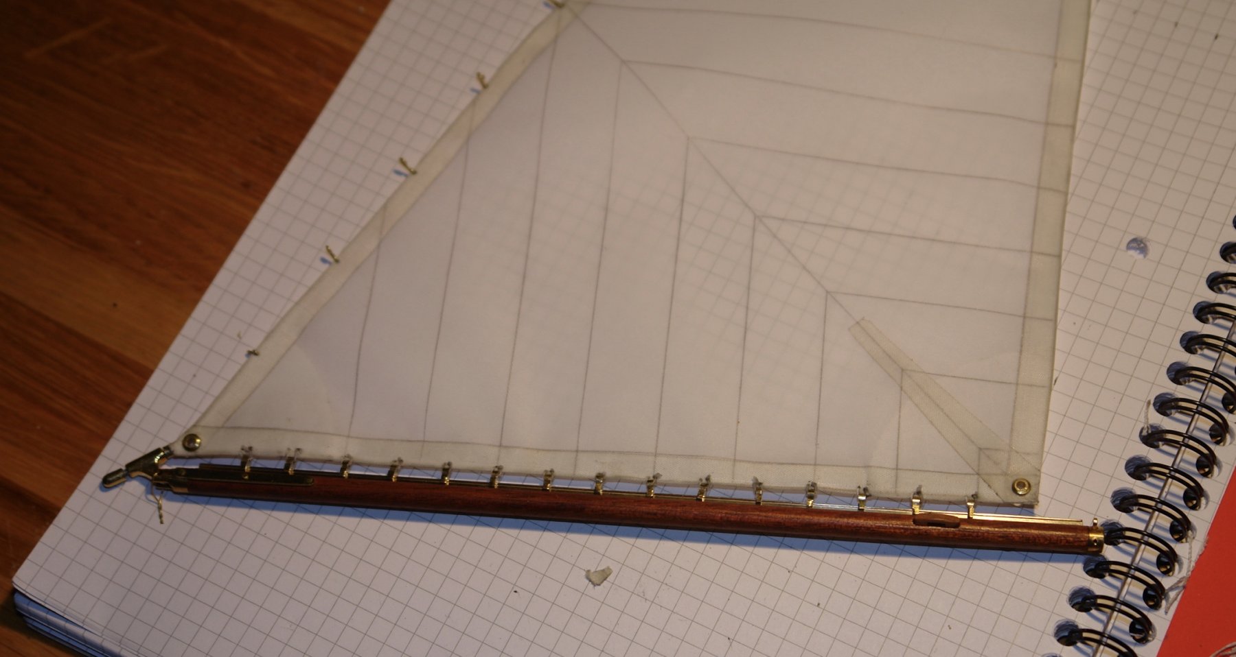
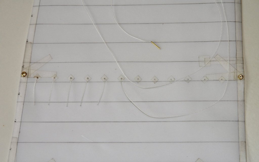
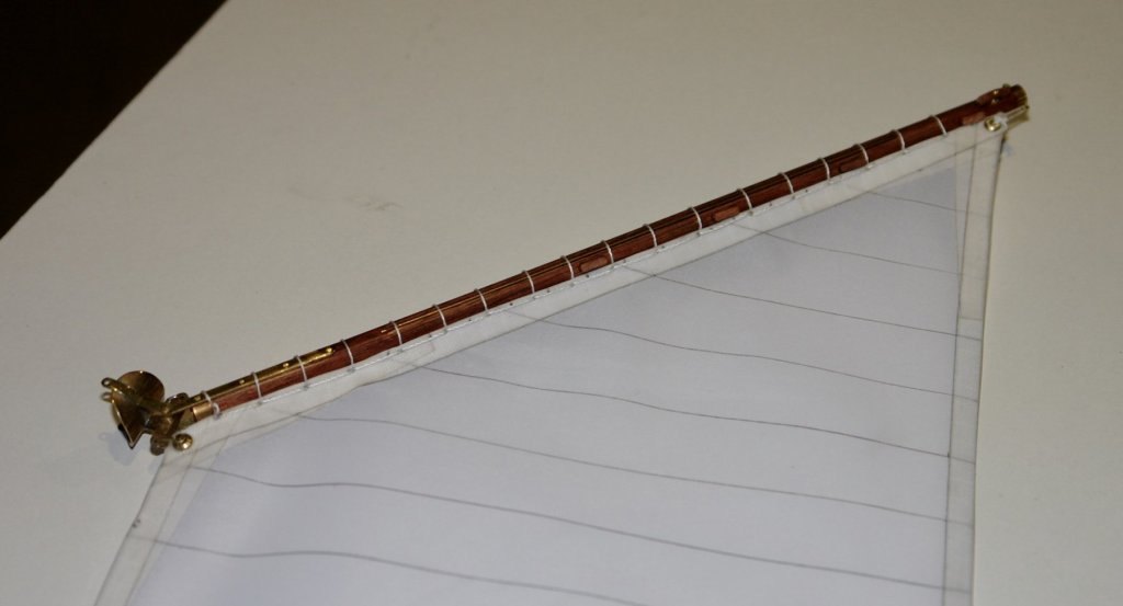
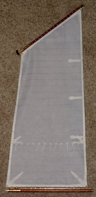
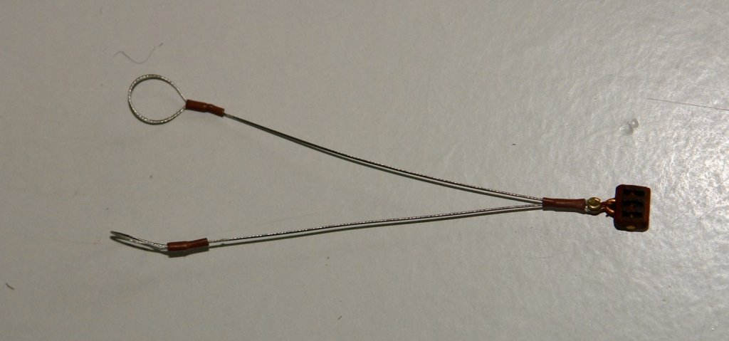
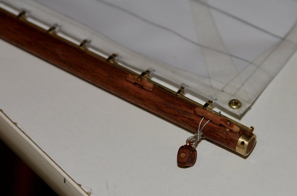
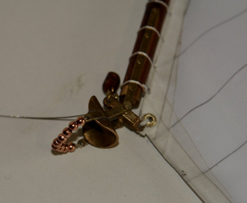
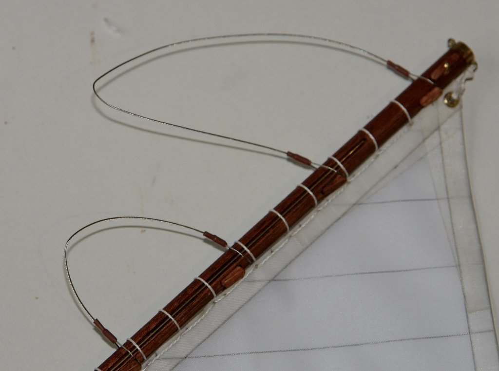
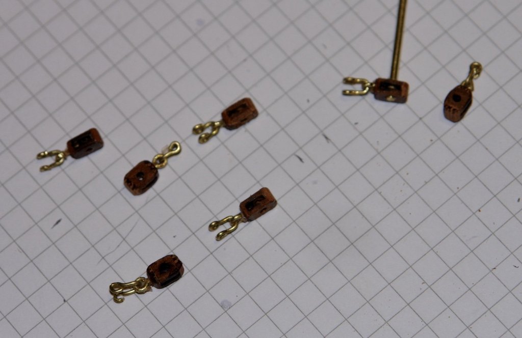
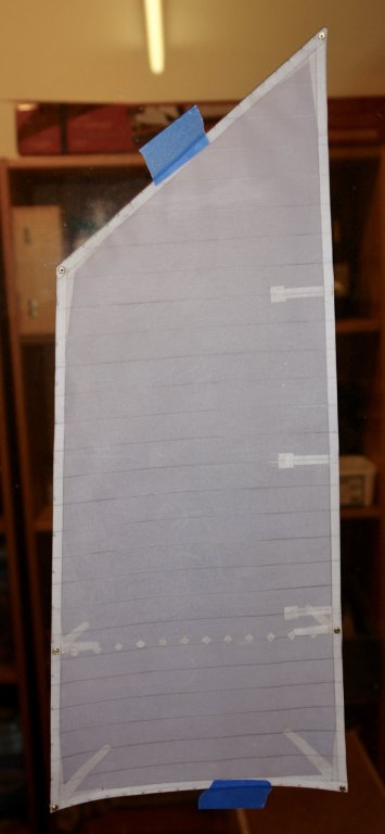
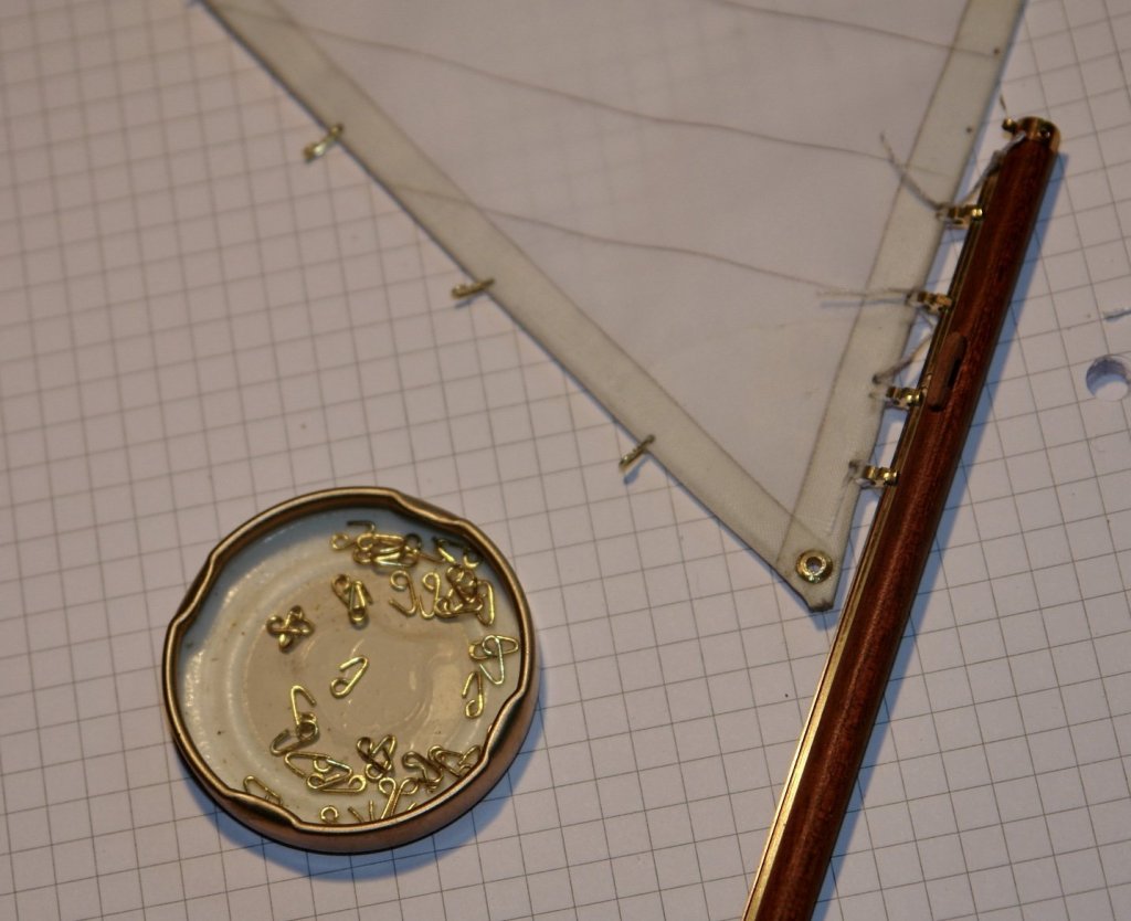
I continue to make the foresail. I'm not keeping an accurate track on time but my estimate is currently between 12 and 15 hours. I have offered it up to the mast and its about 1/4 inch short of what would be an ideal length. Given the amount of time invested I am prepared to live with the discrepancy Anyway to continue:- I put the buntlines on - threaded through the sail. I glued a small bore tube over the line and chamfered the leading edge at 45 degrees to make the threading easier - see photo. I then laced the head of the sail to the gaff. The sliders were sewn to the foot of the sail and then the sliders were gently slipped on to the boom track. I had thought I would get away without inserting battens but decided the leech would hold its shape better with them fitted. I made them from .025" brass wire inserted under rip stop tape. I then went about forming the various attachment points. The strop and the triple block for the gaff lift was made. I fitted the barrel beads - fixed at one end with the other end open for fitting to the mast. The beads are .100" diameter with a .04" hole. The double block for the gaff lift was also made and attached. Another triple block was wired on to the end of the boom to take the boom sheets. Gaff span strops were made and mounted. The single blocks were made for the peak halliard and the boom sheets 7 in all. Thats all for now.


- 882 replies
-
- 14
-
-
Metal work resourcnes
KeithAug replied to Kurt Johnson's topic in Metal Work, Soldering and Metal Fittings
Kurt You might try “Model Engineering - A Foundation Course” - Author Peter Wright. I use it often as my reference book.https://www.amazon.co.uk/Model-Engineering-Foundation-Peter-Wright/dp/1854861522 -
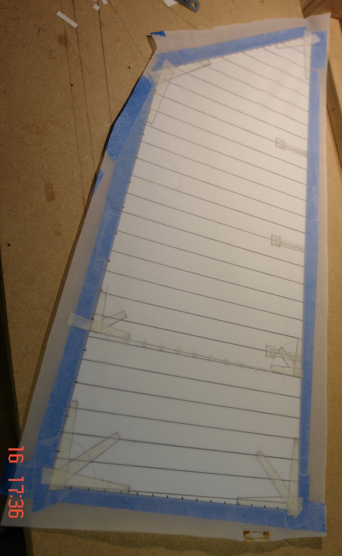
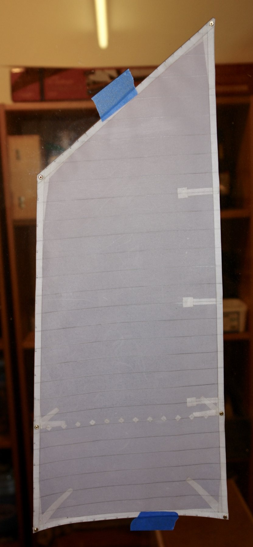
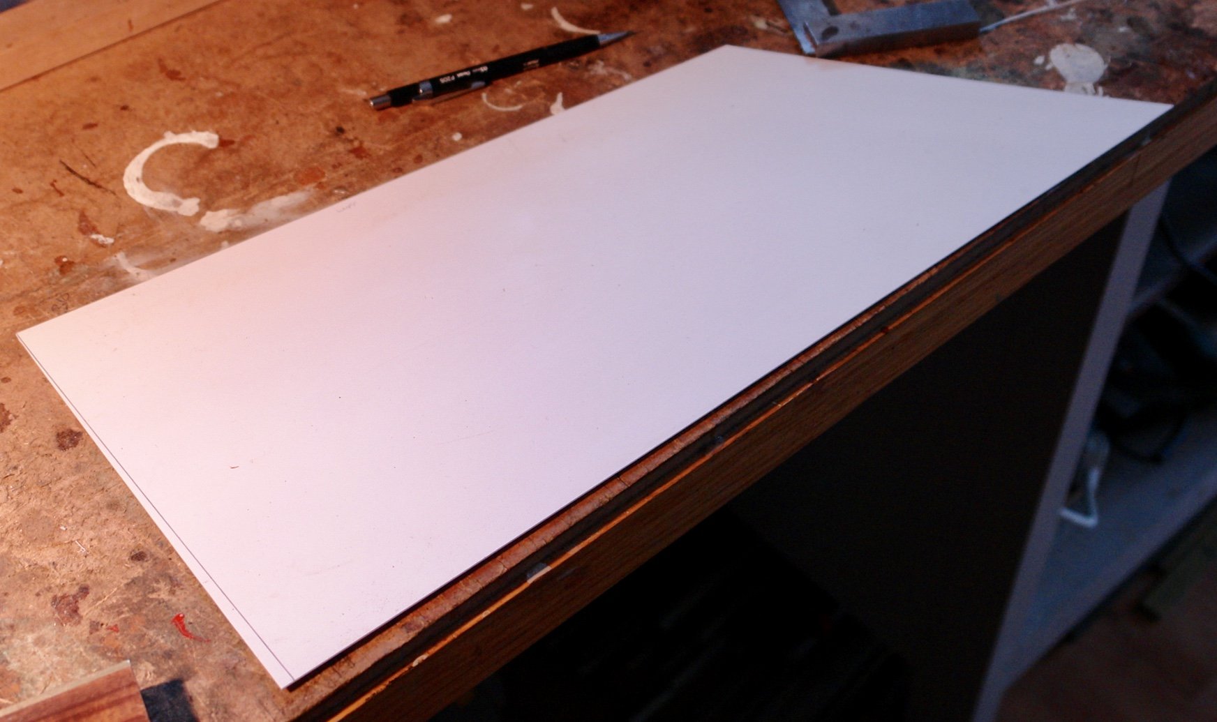
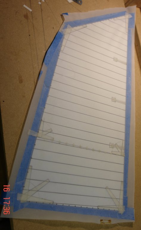
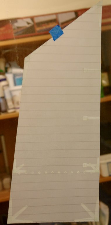
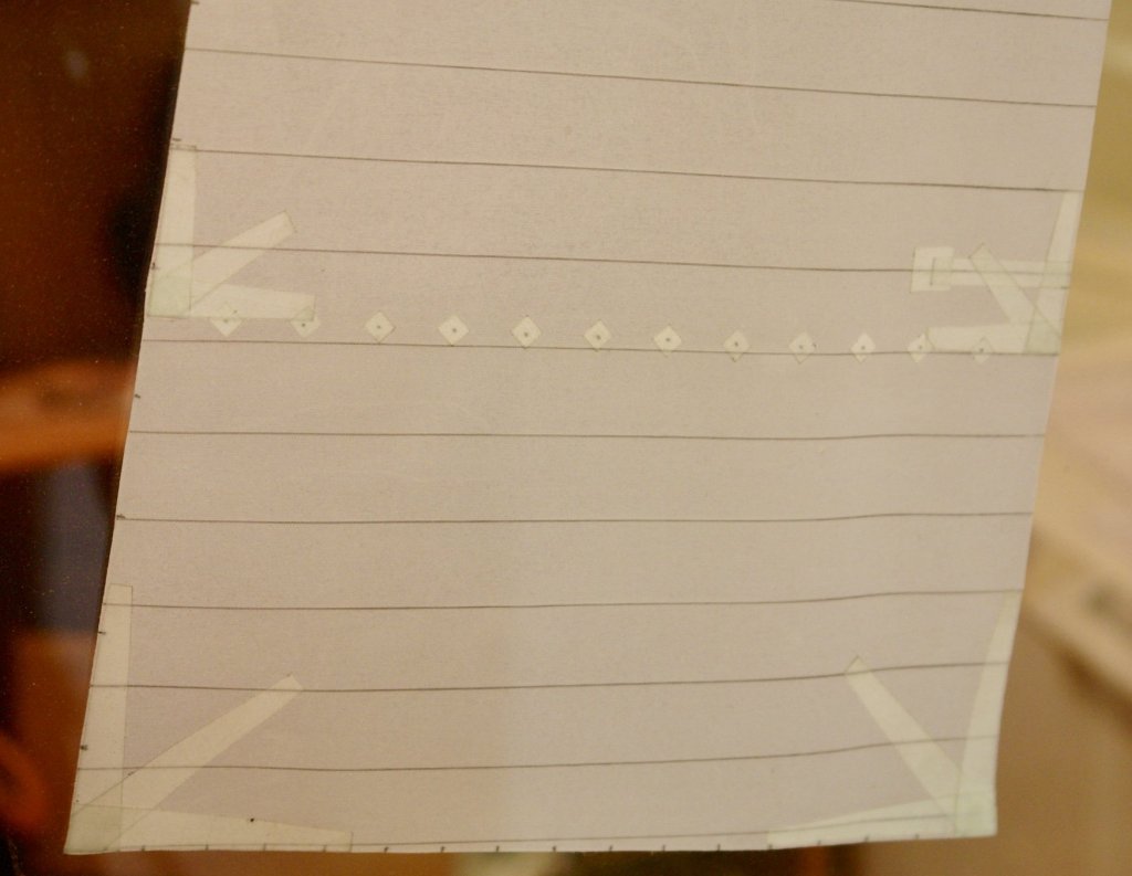
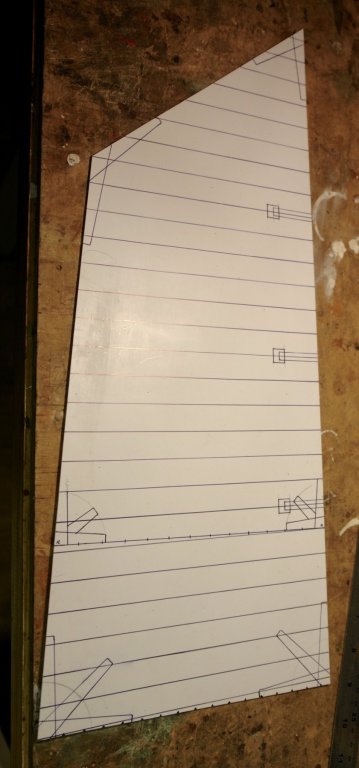
Bedford, How about could do better. When I look at what others have done it sometimes feels like this. Being a bit dissatisfied is maybe not such a bad thing. John, thank you. It is however coming up to its second anniversary and I still think I have 6 months work left. I am resisting the urge to rush and spoil something. I'm looking forward to more of your sea stories. Mark, thank you for your support. Your dedication to the forum is much appreciated by many of us. Mike, thank you for looking in and commenting. Also thank you to all who have visited. I have continued with the foresail. Its taken about 7 hours so far and I am praying that it fits well. While still on the template I attached reinforcing details at the corners and for the reefing lines. I also picked out the detail of the sail battens. I then attached the edge strips with the embedded stainless steel wire. Finally the eyes were added. It is however still not finished as I have to attach the reefing lines, sliders, boom and gaff. Sewing the mast hoops on while they are on the mast is a worry for the future.
-
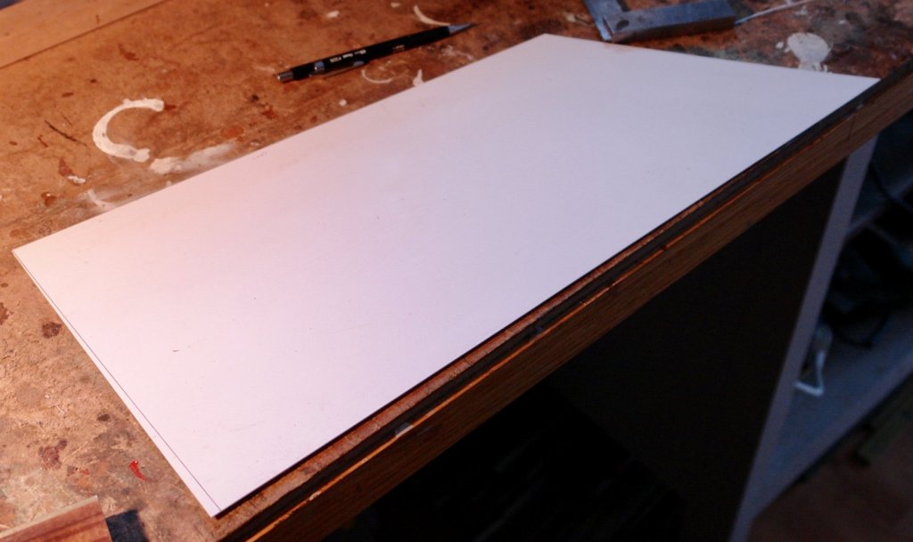
Finally I got back to the workshop and hoisted the jib. I have invested in a set of sewing needles to make into rigging tools. Unfortunately they are in the post. I am hoping they will improve my productivity. I have started to make the foresail. The pattern is complete and I'm hoping the size will be right. It is difficult to measure the exact size as allowance has to be made for mast hoops, sliders etc. I half expect that I will be making this sail twice in order to get it right.


-
Nils Looking good and such quick progress. A very happy birthday to you.
- 692 replies
-
- 4
-
-
- eagle of algier
- chebec
- (and 2 more)
-
Adrian, Today I spent a interesting hour visiting Cromer and the current RNLI lifeboat and so I was prompted to revisit your beautiful build. I look forward to watching you finish it.
- 184 replies
-
- 3
-
-
- ruby & arthur reed
- lifeboat
- (and 1 more)
-
A bit drastic. I thought it was a pretty creditable attempt.
- 83 replies
-
- 3
-
-
- melvin
- blue devil
- (and 2 more)
-
As another week away with family comes to a close I feel humbled to reply to all of you who have visited and left such kind comments. Denis, Nils and Pawel, nice of you all to take the time to visit and leave comments. Richard, thank you once again for visiting and leaving your message of encouragement. Michael, thank you for leaving your house move for long enough to catch up. Tom, Thank you for looking in. Noel, Thank you for taking the time to read through my log and for your conversion to the beauty of modern yachts. It is true that, relative to many vessels featured in this forum, Altair is a relative newcomer at a little under 90 years old. She is however based on designs current in the first decade of the 20th century and was somewhat dated compared with her contemporaries built in the 1930's. To all of you who have visited and hit the like button many thanks. I hope to get back on the build over the coming weekend. I find enforced separations from the workshop leave me anxious to get home.
-
Kevin, I think the MDF will give you much greater rigidity. Have you considered 1/8" ply and rejected it? The build is looking good.
-
Neil - a bit of a long shot - Did you serve on the Blue Funnel Line and if so did you come across Captain Michael Tomlinson?
-
Neil Deans marine have a good selection of cargo vessels. You may find something here. http://deansmarine.co.uk/shop/index.php/cPath/10_20
-
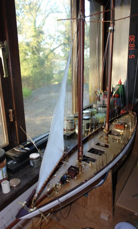
Thank you Kees and Nils. I spent a bit of time hoisting the staysail. I think I may have to invest in some rigging tools. Suggestions would be most welcome. I want to set the sails close hauled on a port tack. The natural action of the sheets and blocks is to hold the booms aligned fore and aft on the centre line. To hold the booms to starboard I need to rig preventers which is a bit unusual for this point of sail. I will console myself by assuming the helmsman has has too much grog and the crew as a result are nervous about the possibility of an unintended pirouette. This is not as far fetched as it sounds, a very long night in the Wide Mouthed Frog and a next day hangover while plugging the tide through the Sound of Luing produced just such an event. Setting the sail was a slow process, primarily because I had to make a few more blocks as well as finishing off some of the foredeck detail. Here are a few photos:-


- 882 replies
-
- 14
-
-
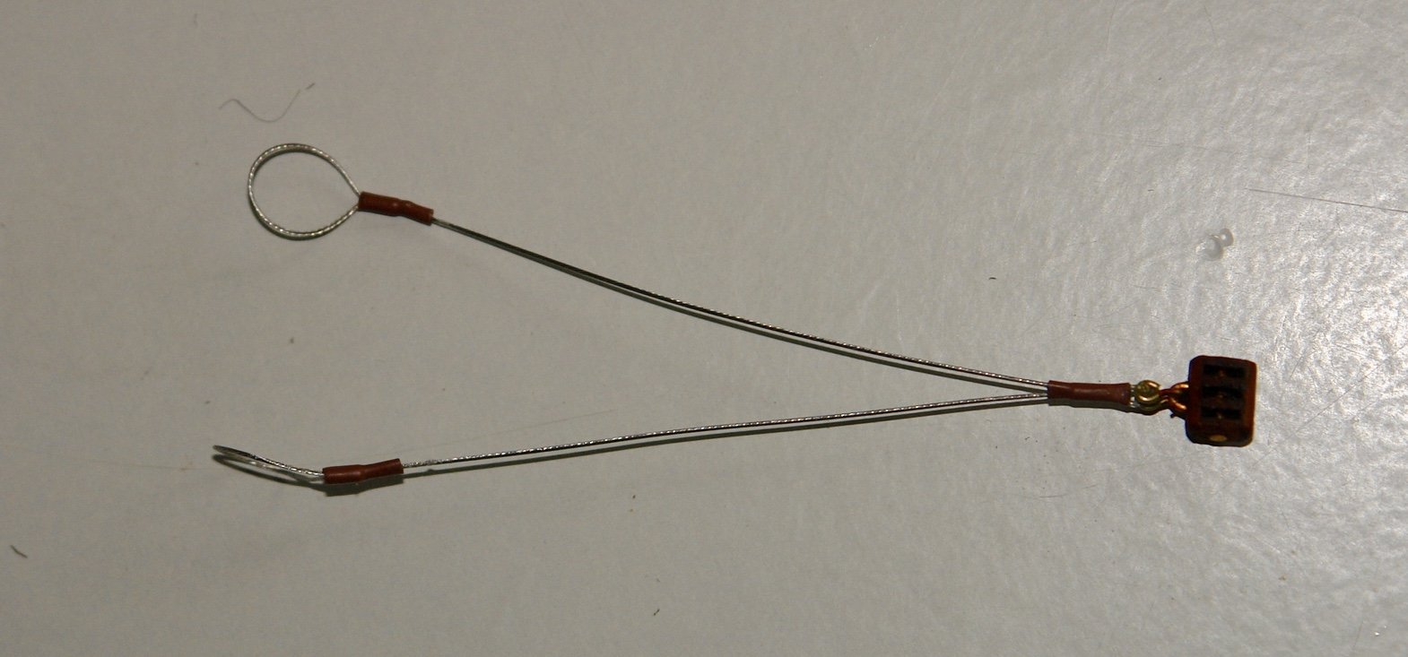
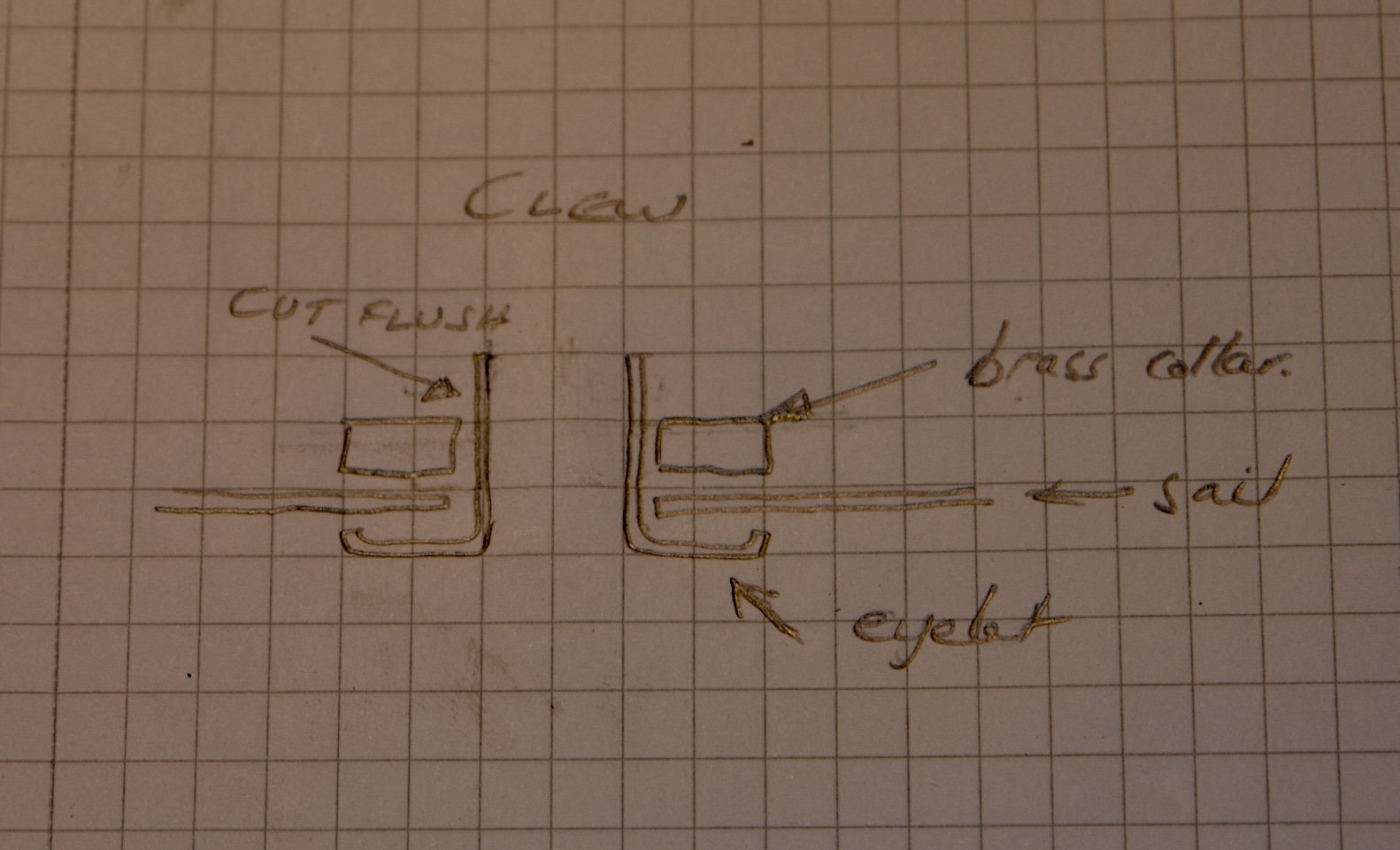
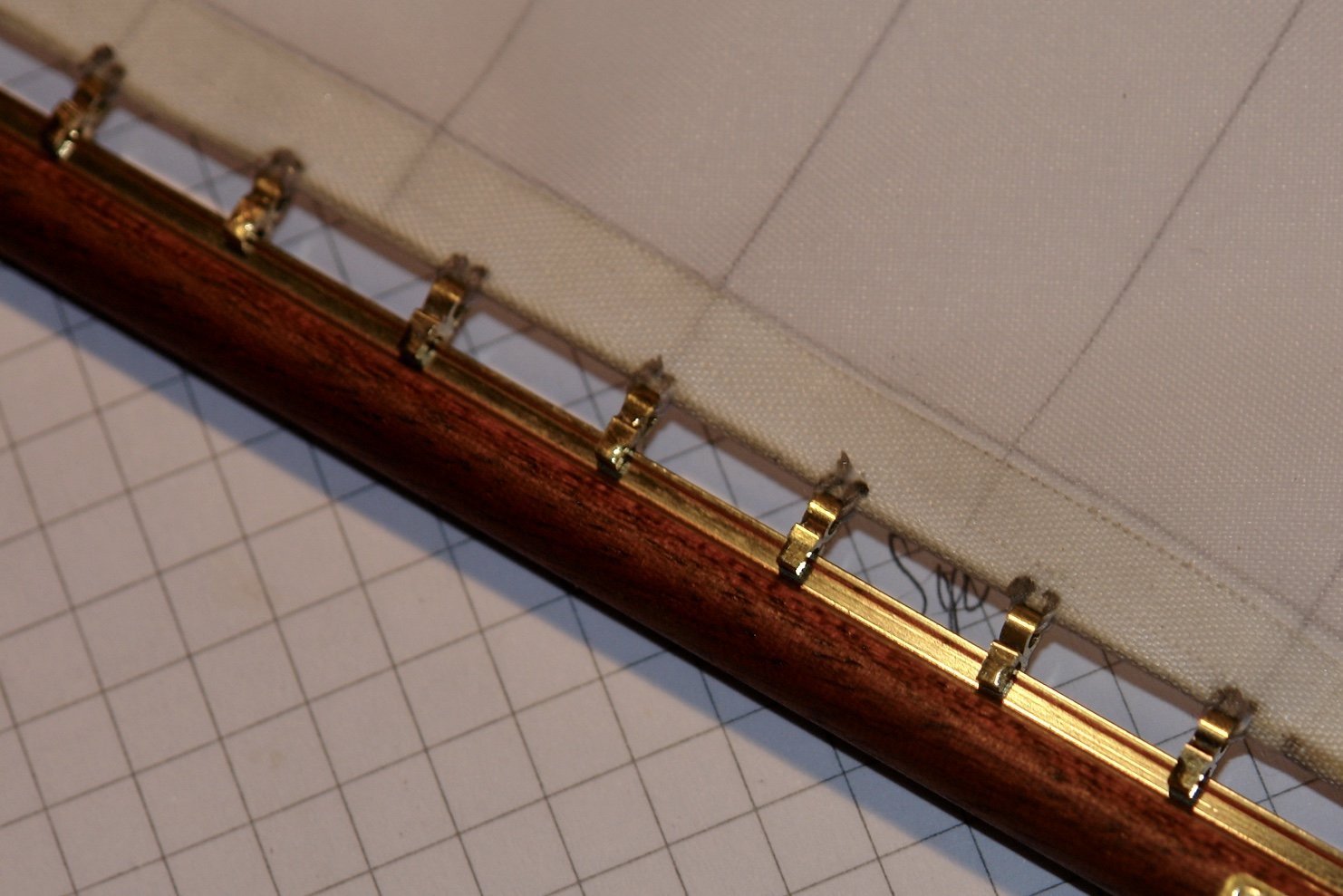
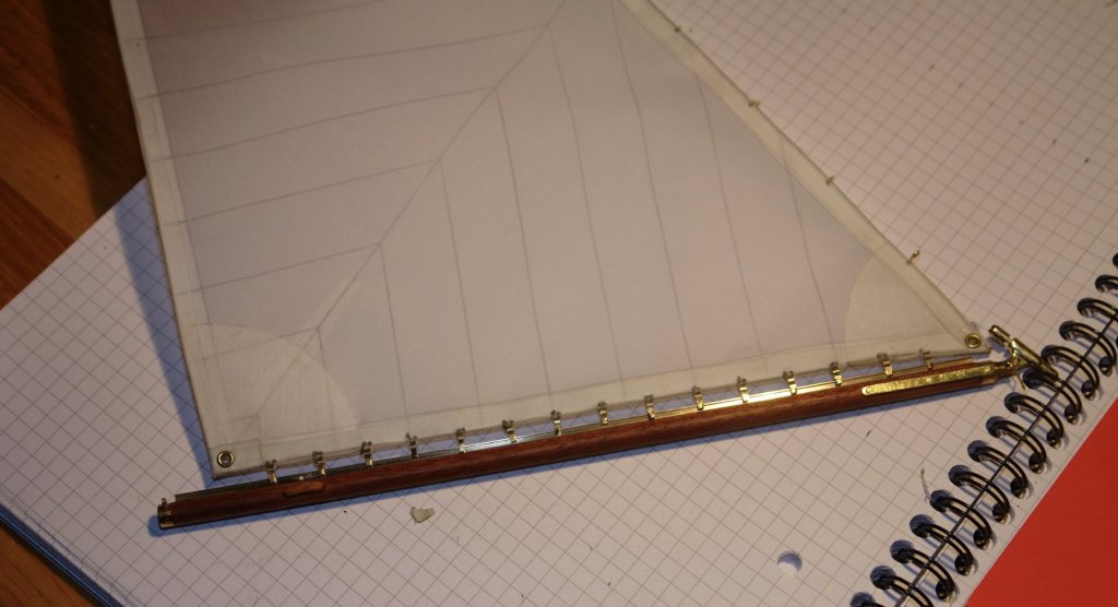
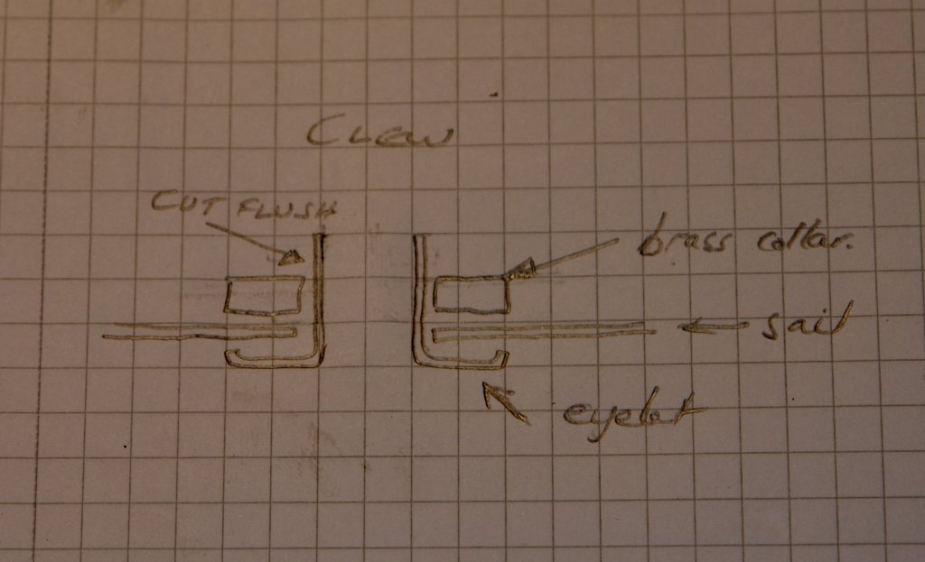
A small update. I decided to try insetting separate wires into each edge of the sail rather than making a triangular hoop as previously described. This worked better as I could get the wires more taught and hence straighter. The penalty was lack of edge reinforcement at the corners. A small penalty which I don't think will matter. I decided to complete the staysail to test how it would look. Rings were inserted (tack head and clew). They were made from eyelet washers but rather than splay the end I put a machined brass ring on the shank as per sketch and glued it with CA. I spent a few hours last night sat in my chair making hanks out of .015" brass wire. These were inserted through the sail (behind the edge wire) and crimped in place. I then started sewing the sliders along the foot of the sail. When I went to school boys did woodwork and metalwork and girls did needlework and cooking. I fear I may have missed an important part of my education. I did a test after attaching 4 to make sure they would slide on. Once attached the sliders were eased on to the staysail boom. All went well. A close up to show the sliders / attachment stitching.


- 882 replies
-
- 12
-
-
Hellmut, An interesting description of your workshop. I hope you get many years of pleasure out of it and that over the years your children come to value what you make.