KeithAug
-
Posts
3,986 -
Joined
-
Last visited
Content Type
Profiles
Forums
Gallery
Events
Everything posted by KeithAug
-
 Nils, nice rudder work. I’m constantly surprised how small the rudders are on some sailing ships.
- 692 replies
-
- 5
-

-
- eagle of algier
- chebec
- (and 2 more)
-
Jon An interesting parallel furrow we plough. I spent today rigging the main boom on Altair. Not quite as complicated as Blue Nose. How about a cocktail stick rather than a tooth pick.
-
Hmmmm! Glad I decided to have my masts fixed. This all looks very interesting and complicated. Good luck Jon.
-
Jon, I just spent a pleasurable hour catching up with you build. Your rigging is looking very professional.
-
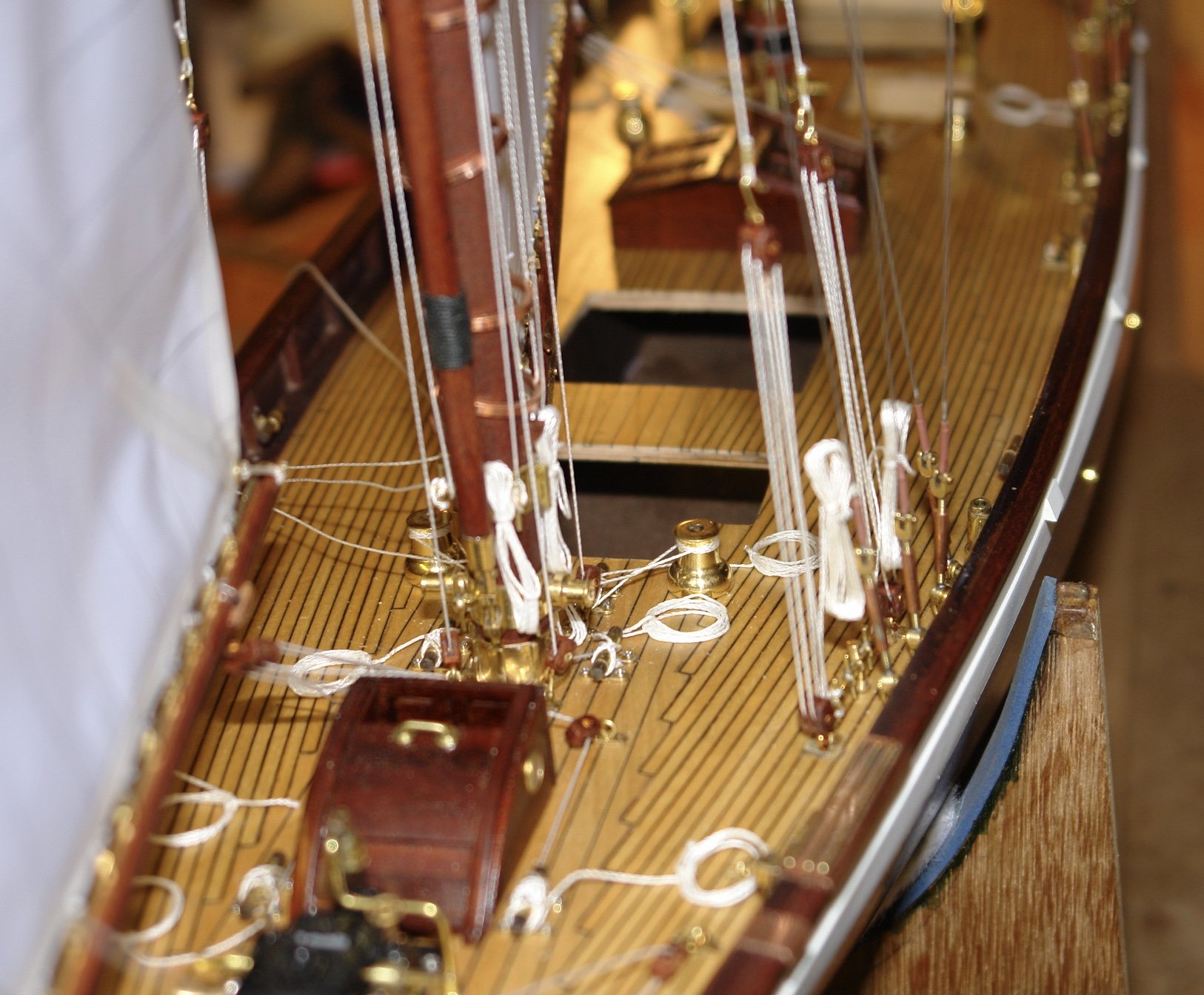
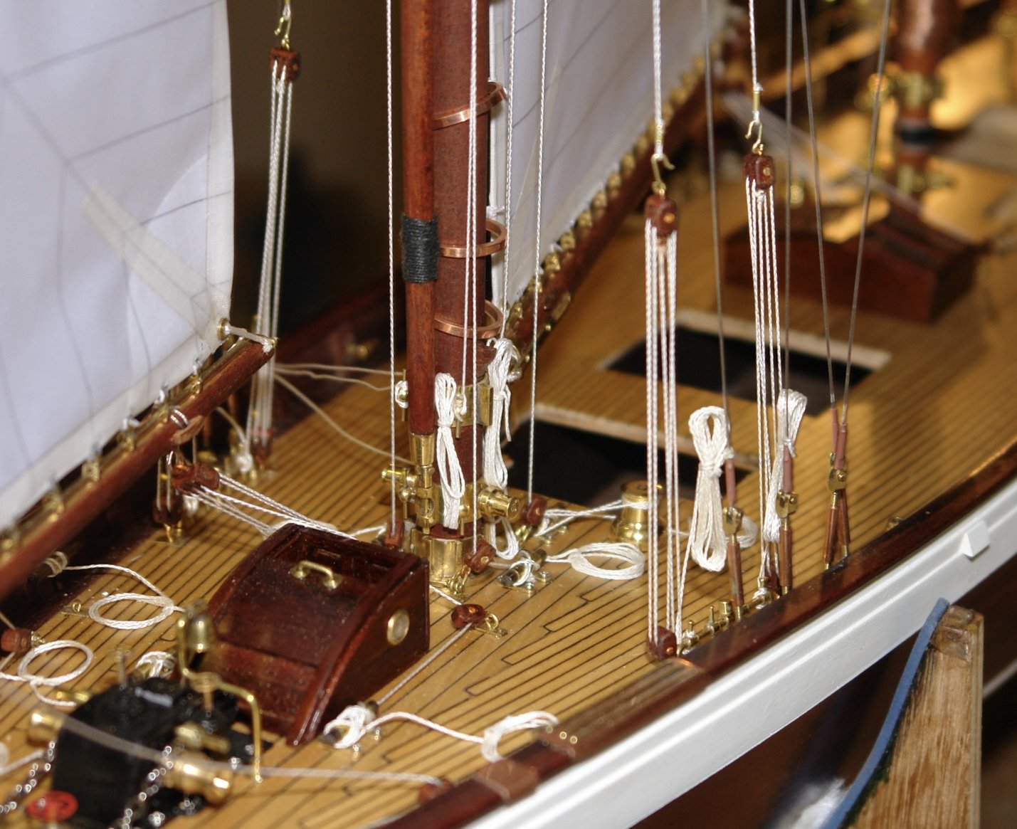
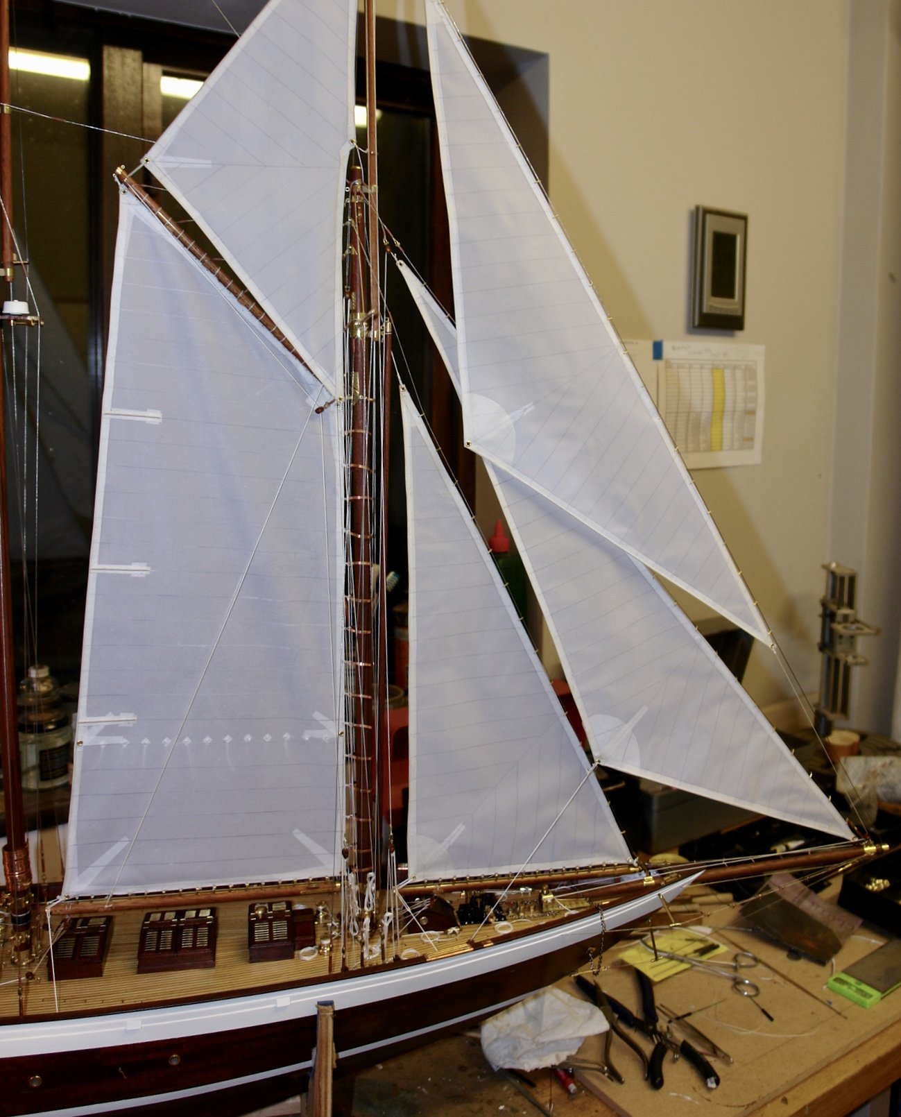
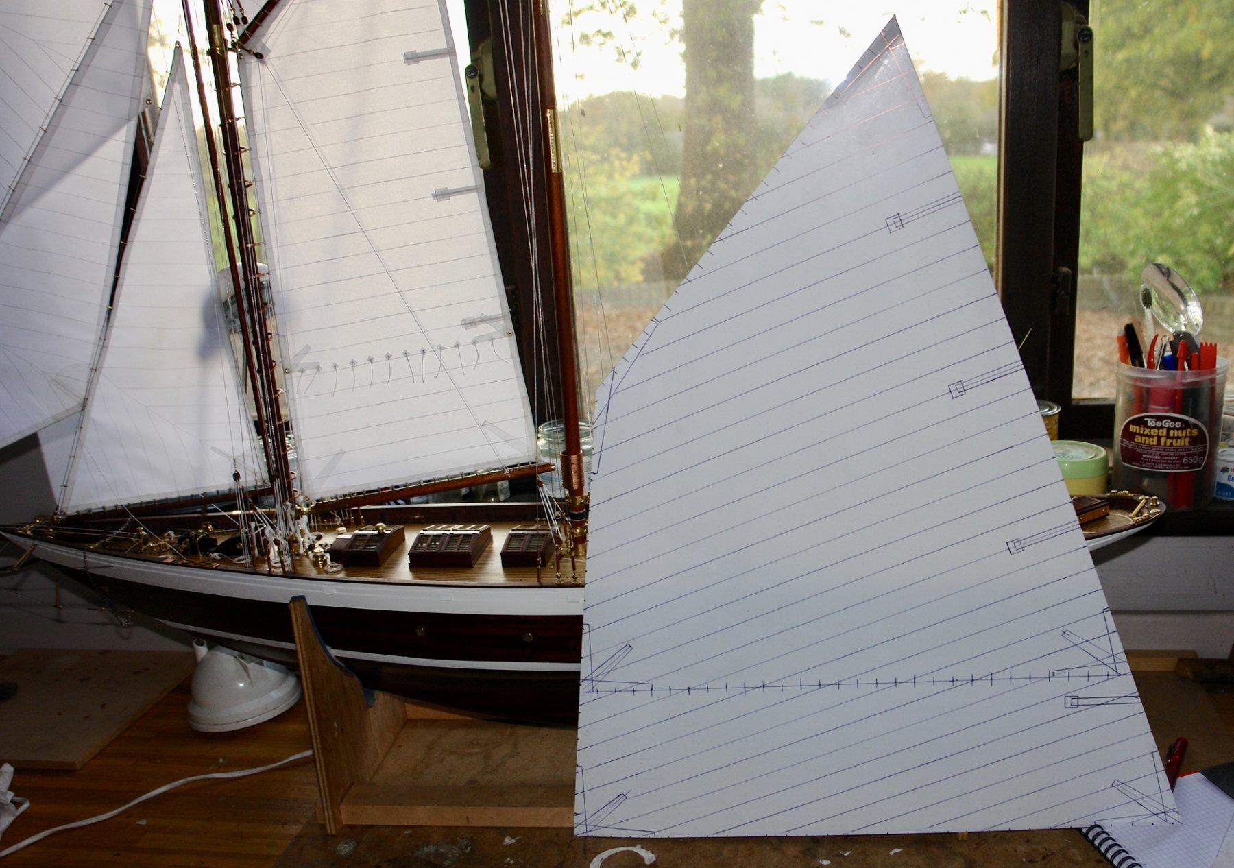
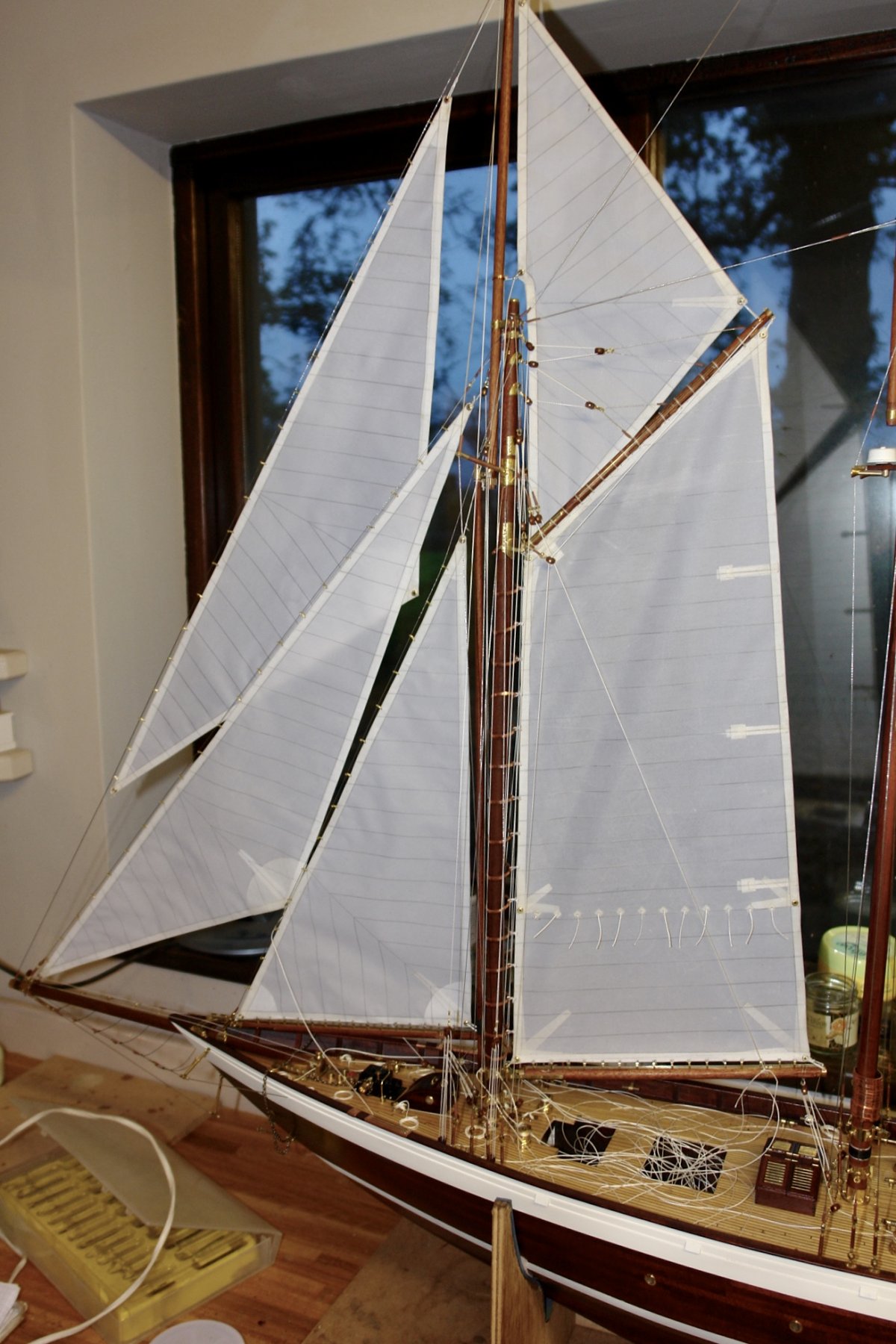
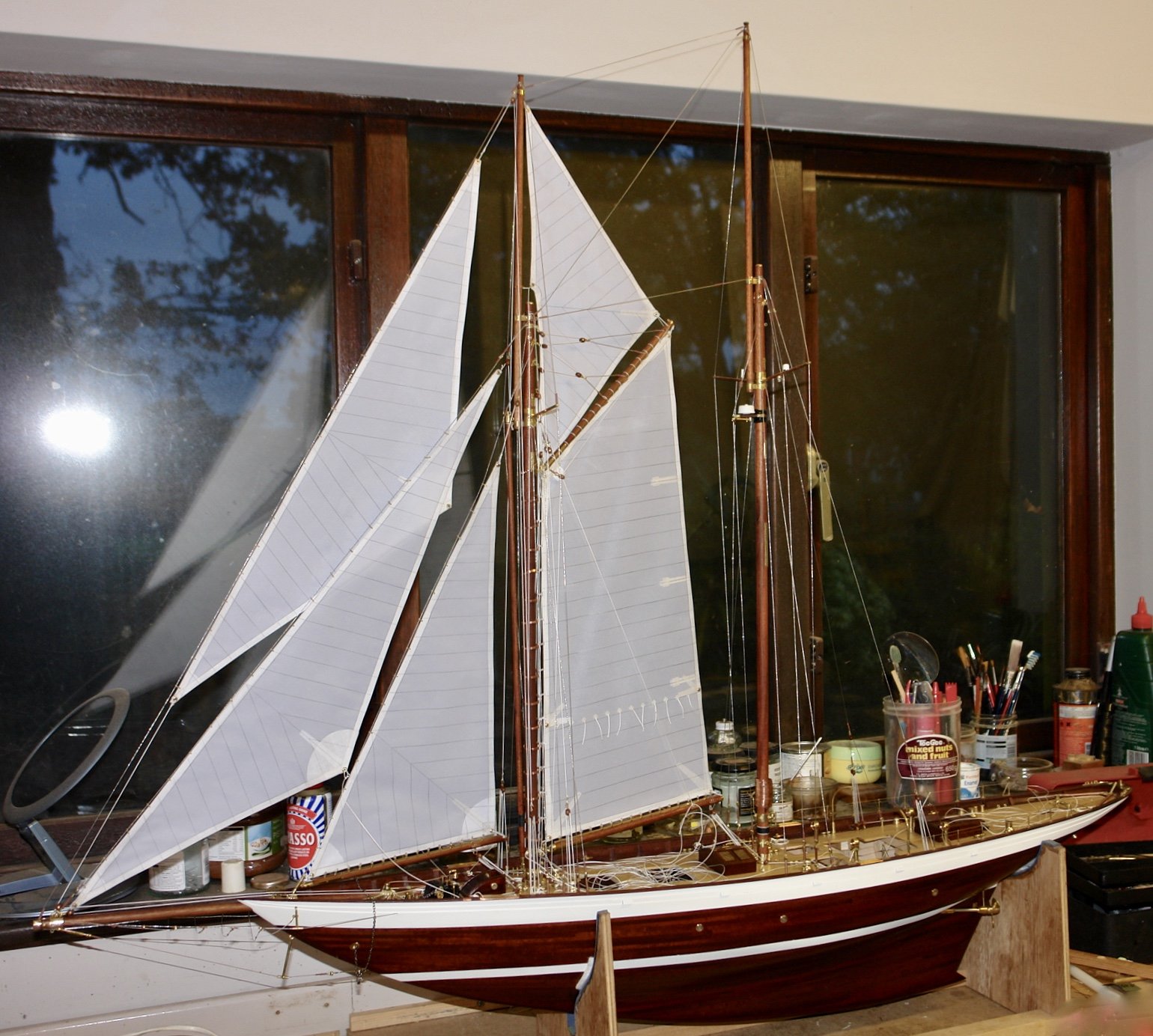
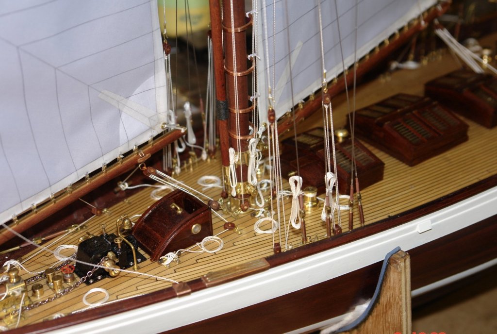
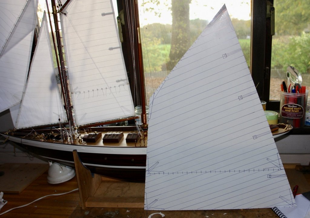
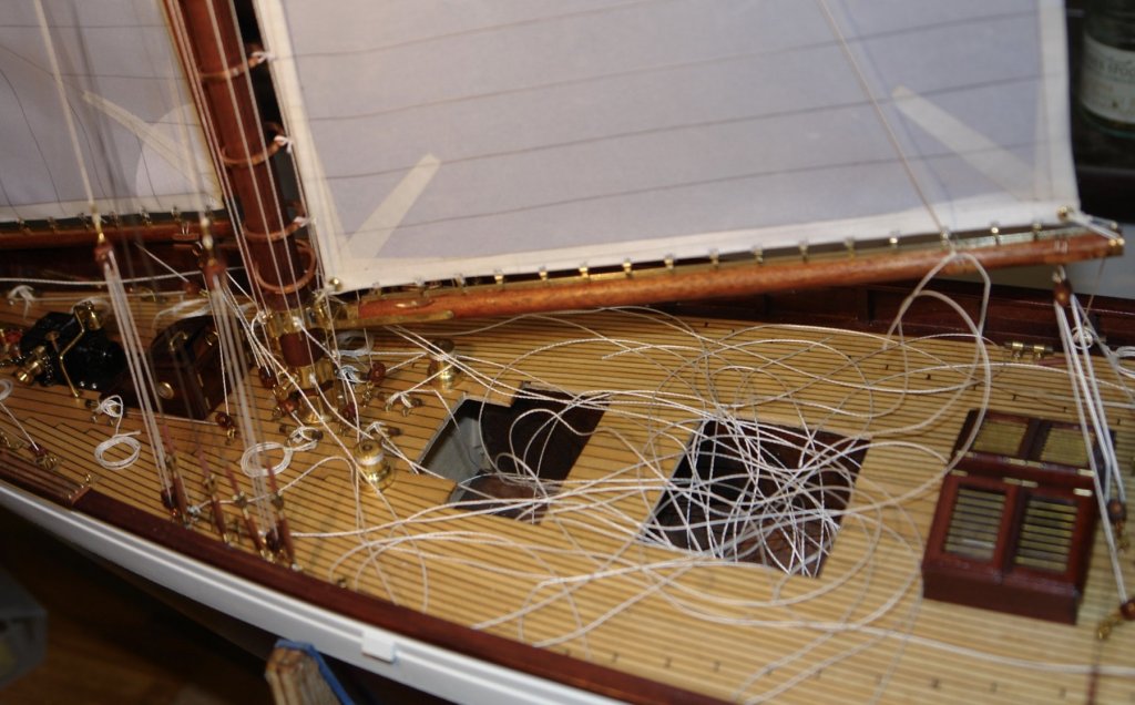
Mike, Thank you. Hello Dan, it feels like a big learning curve for me. I have never sailed or rigged a gaff rigged vessel before so I seem to be taking a lot of time checking and rechecking what I am doing. I hope most of it right but I guess some of it comes from my imagination. A brief (mostly pictoral update) follows:- I got round to tidying up the rats nest of tails and she is now all "Shipshape and Bristol fashion". I then spent several hours making the template for the rather large mainsail. I have marked on all the seams, batten pockets, reinforcing, buntlines, slider, mast hoop and gaff lacing positions, much as I did with the foresail. I offered the template up to the mast a couple of times and trimmed it to get it to what seemed to be right. I feel more confident with the sizing than I did with the foresail, however as the say "Confidence often comes before a fall" - time will tell!


-
What is the trade name / type of resin and silicone you are using Nils. I have never tried resin casting but would like to try it some time. The planking looks very neat.
- 692 replies
-
- 4
-
-
- eagle of algier
- chebec
- (and 2 more)
-
Per, Kees, John, Richard. Thank you for looking in and commenting. Richard, I see you too have sleep problems. Internet at 4.30am !!!!!!
-
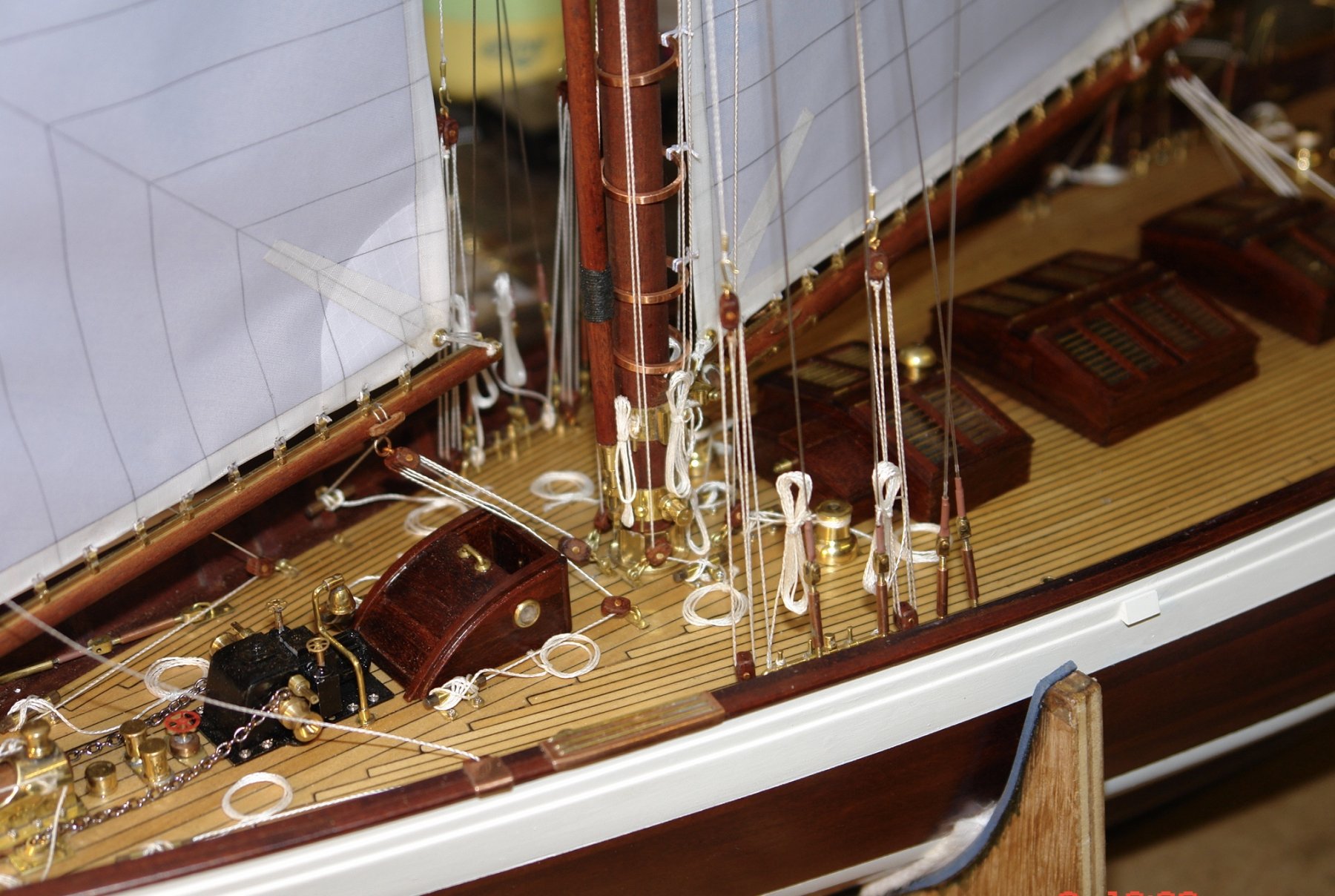
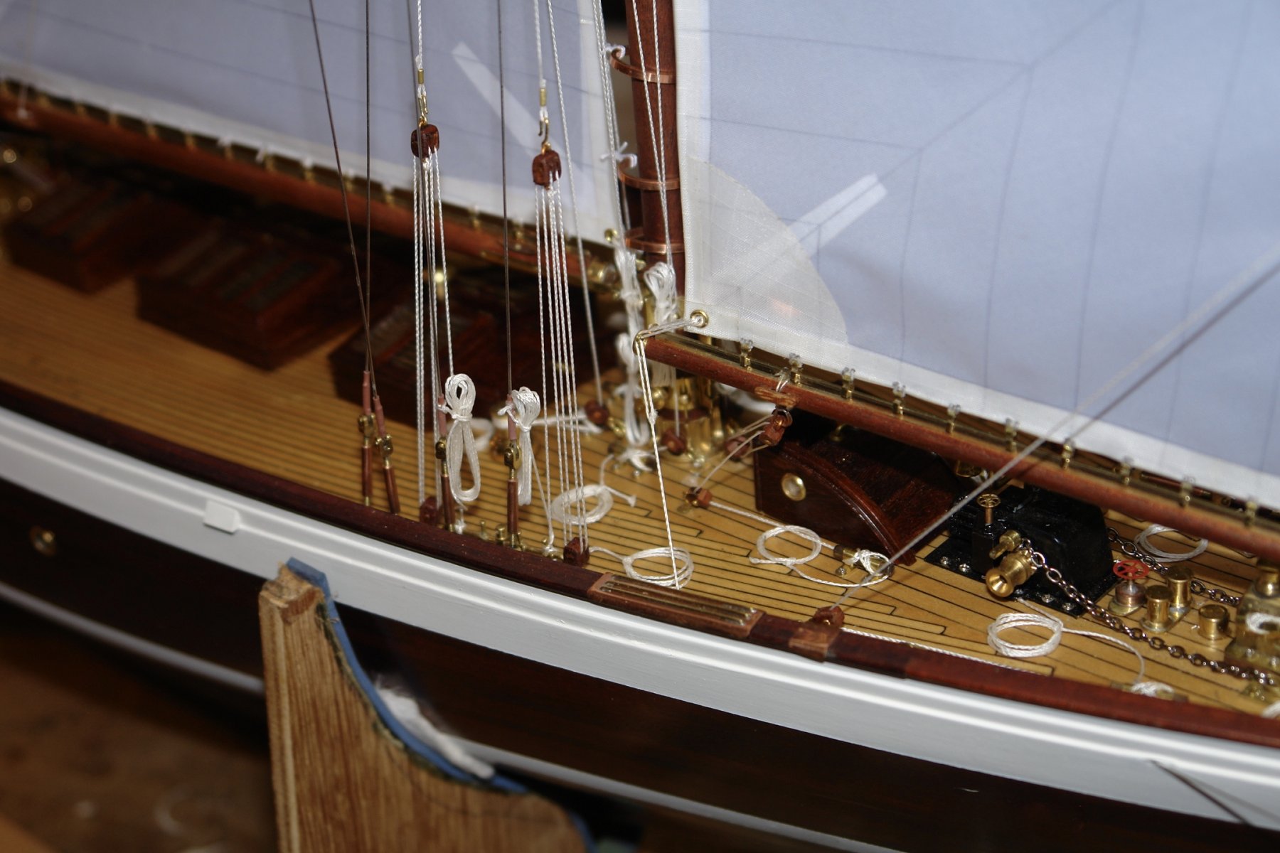
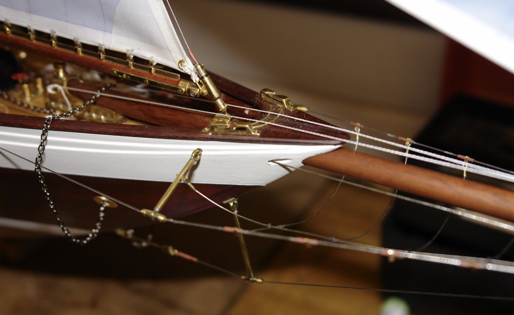
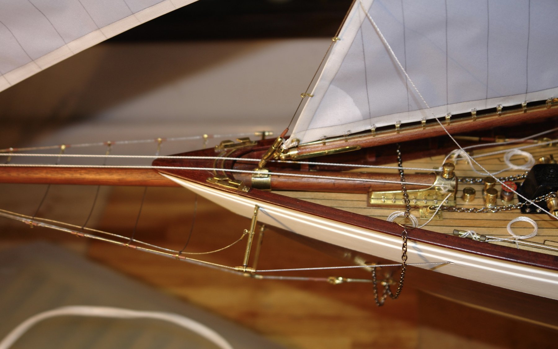
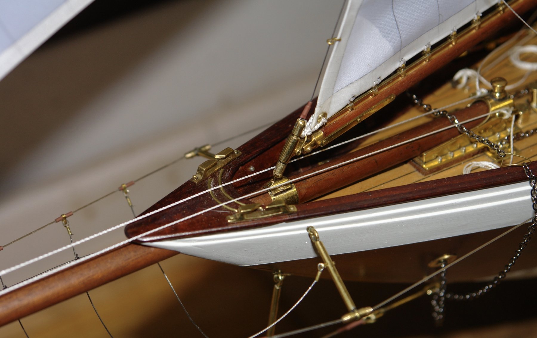
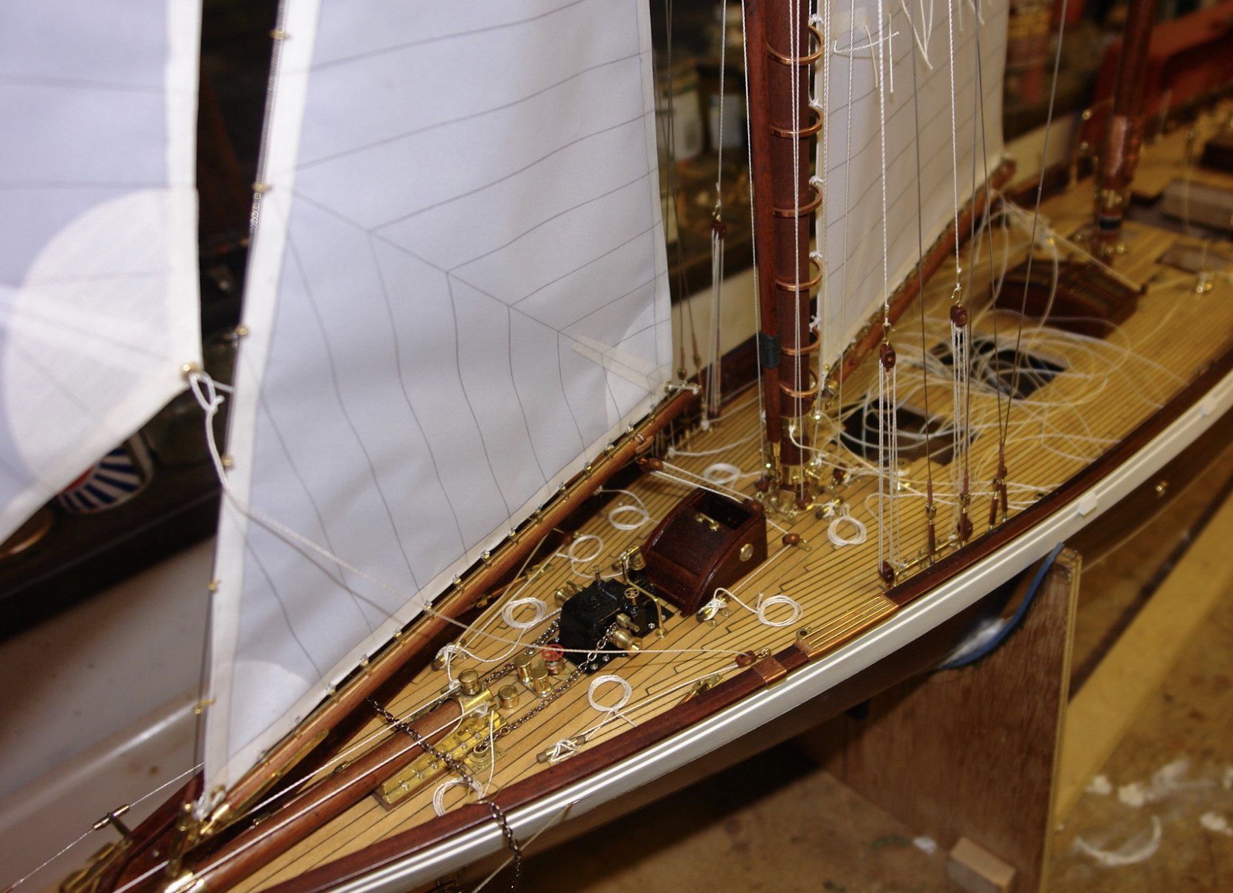
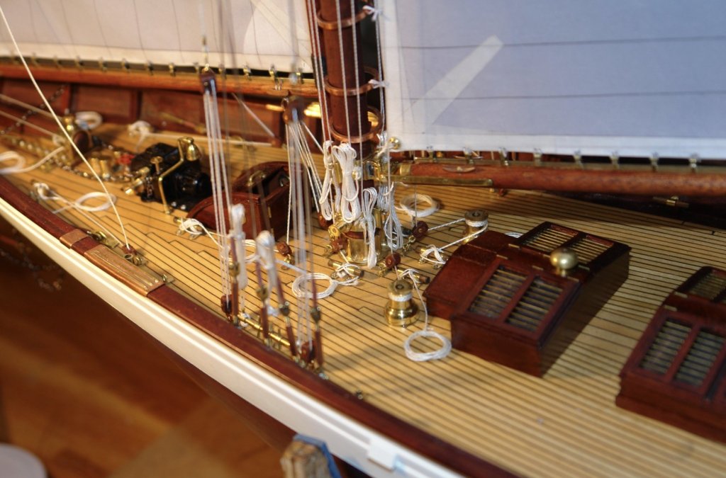
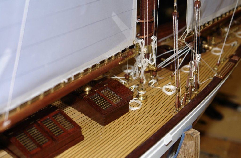
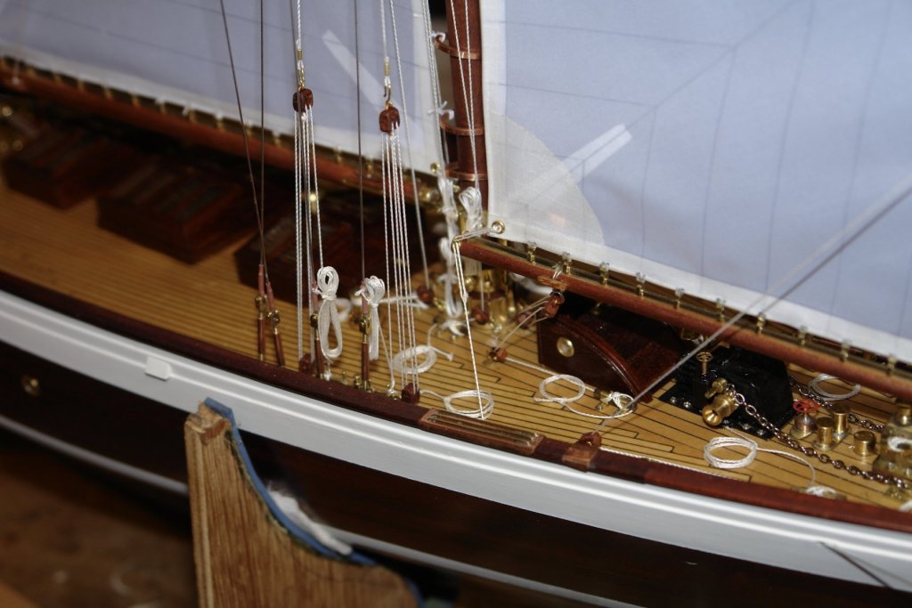
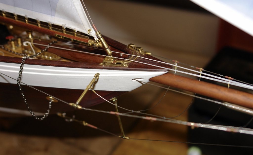
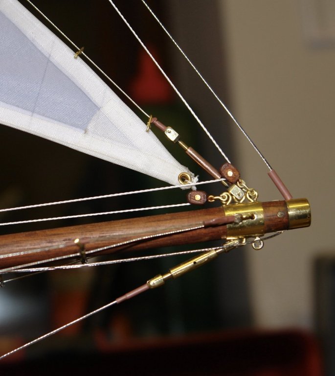
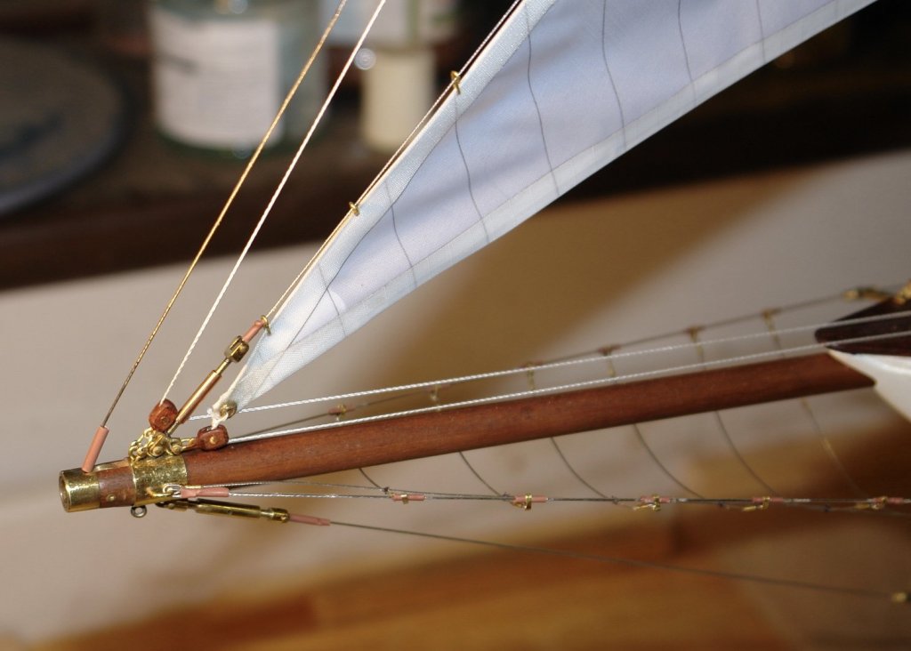
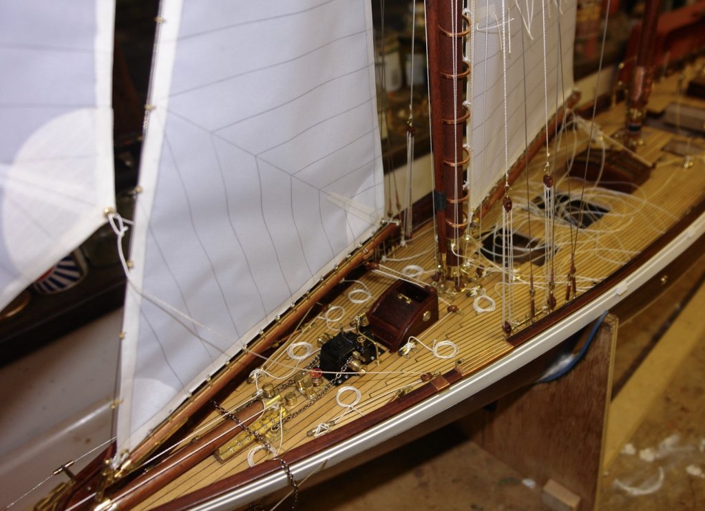
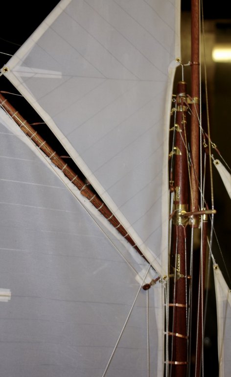
Thank you Nils. And so on to the flying jib. I had to rig the stay first. The stay starts on the deck with a turnbuckle which lays alongside the bowsprit. It then passes through a hole in the bow (fortunatlely spotted and bored some time ago). Then it passes round a sheave before heading off on a long journey to the head of the fore topmast. I am having to be careful with tension. The masts are still flexible in the fore and aft direction and therefore prone to bowing. The problem is the lack of main topmast backstays, left off pending rigging of the mainsail and main topsail. The two lines passing through the blocks at the end of the bowsprit are attached to the tacks of the jib and flying jib. These pass over the rubbing strips on the bow and are anchored on to the cleats on the bowsprit foot. By this stage I have a real rats nest of tails on the deck ready for a good tidy up. But at least the flying jib is aloft and flying nicely. I have not however attached the flying jib sheets as yet. They land on the deck well aft and I don't want them to get in the way of rigging the mainsail.


- 882 replies
-
- 16
-
-
Saw blades for Byrnes saw
KeithAug replied to mikeaidanh's topic in Modeling tools and Workshop Equipment
Kevin I should have added that I try to preserve my Byrnes TCT blade by doing roughing operations with this TCT blade:- https://www.amazon.co.uk/gp/product/B018RSRT82/ref=oh_aui_detailpage_o06_s00?ie=UTF8&psc=1 Don't be fooled by the claimed thickness as this is the thickness of the disc. The Kerf is 1/10". That said it cuts cleanly if you don't mind wasting a bit more wood. The bore is 20mm so you still need a spacer. -
Saw blades for Byrnes saw
KeithAug replied to mikeaidanh's topic in Modeling tools and Workshop Equipment
Kevin I agree with Ed re the use of carbide blades - I only use them for cutting larger stock (3/8 inch and above hardwood). Jim has reducers available and the implication is he will make the size you want for $5. Might be worth adding it to your order. Alternatively I can make one and send it to you. -
Lovely job Mark. I get the impression that much of your brass work is hand made without the use of machine tools. Am I correct? Do you have machine tools Lathe / Mill etc?
-
Kevin, you are not the first and will not be the last - been there, done that! I am enjoying following the build.
-
Saw blades for Byrnes saw
KeithAug replied to mikeaidanh's topic in Modeling tools and Workshop Equipment
Mike this UK supplier has a large range, but again you will need a spacer. I have good experience of this supplier. https://www.chronos.ltd.uk/cgi-bin/sh000001.pl?WD=saw slitting diameter 80mm&PN=Metric_HSS_Slitting_Saws.html#aSS1003 -
Saw blades for Byrnes saw
KeithAug replied to mikeaidanh's topic in Modeling tools and Workshop Equipment
Mike It depends on what type of blade you want. If it's slitting saw blades then I uses this for most of my work - particularly slitting off planks for hull and deck planking. https://www.amazon.co.uk/gp/product/B00AUB66C0/ref=oh_aui_detailpage_o01_s00?ie=UTF8&psc=1 I also have 0.6mm and 1.0mm versions of the same blade - from the same supplier. You can get similar blades with coarser teeth but I find 108 teeth are best for most uses. Bear in mind the shaft on the byrnes saw is 0.5" diameter while these blades have 22mm bores. I made up a spacer (on the lathe) from an off-cut of 25mm aluminium bar. If you are looking for carbide tipped blades then the only source I have found for small kerf (.040") blades is Byrnes Model Machines. If you want any more details of the spacer I am happy to supply. -
Thanks for the story Dan, very interesting. I Sometimes have to remember the scale of this build - just to remind myself how detailed your work is.
- 287 replies
-
- 4
-
-
- michelangelo
- ocean liner
- (and 1 more)
-
Its all going rather well Nils. I enjoyed your untwisting solution. The build is going so quickly i will be soon asking "what next". .
- 692 replies
-
- 4
-
-
- eagle of algier
- chebec
- (and 2 more)
-
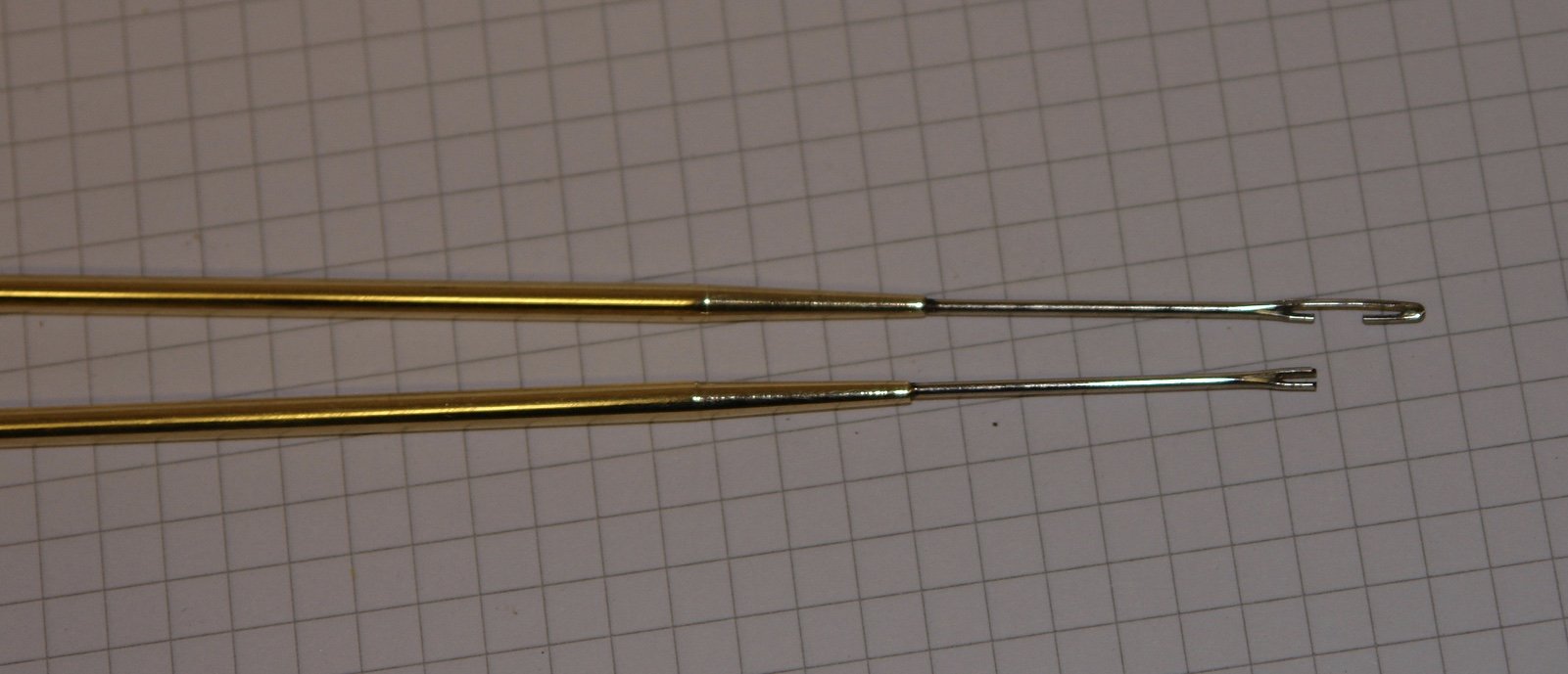
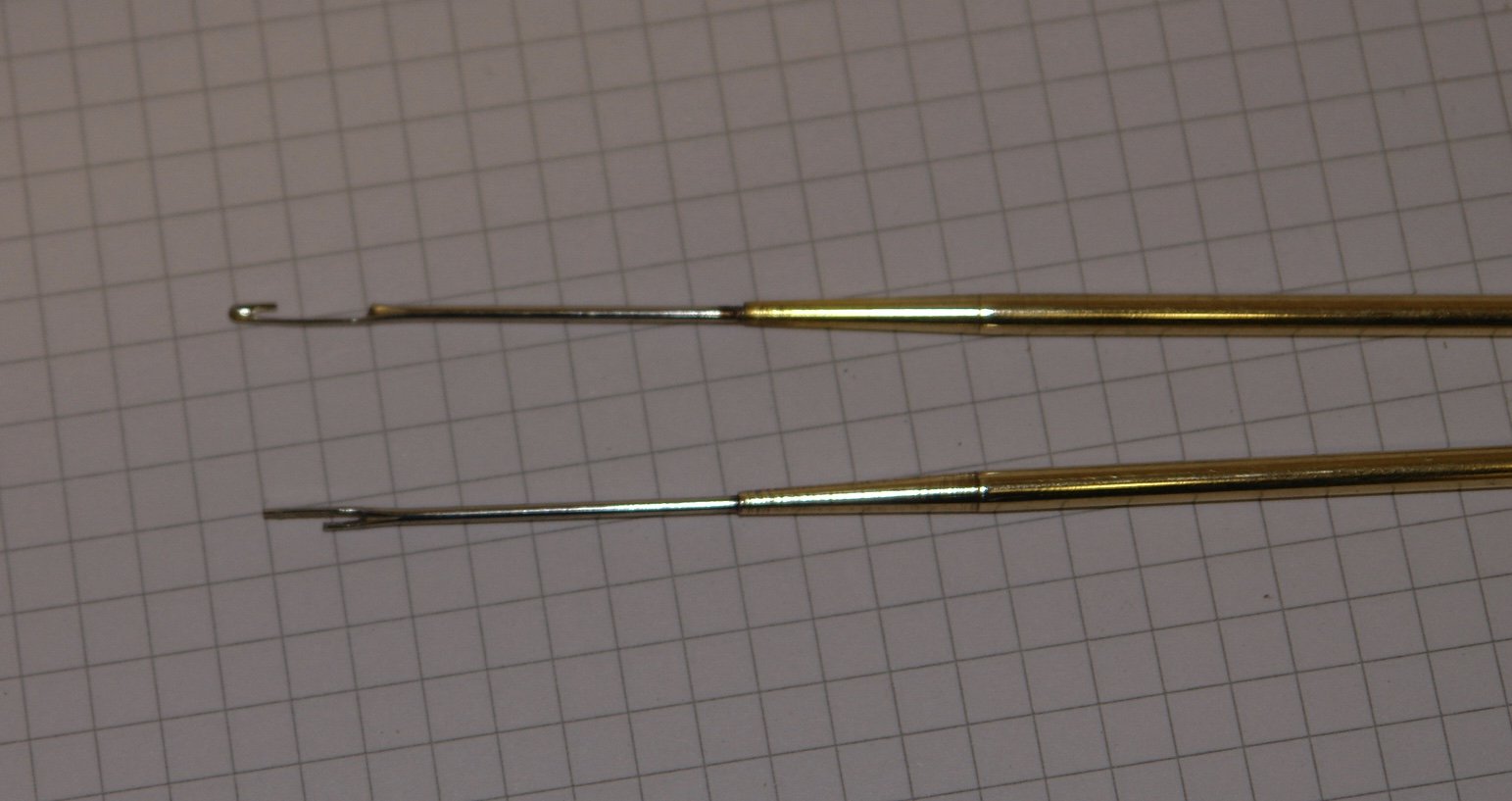
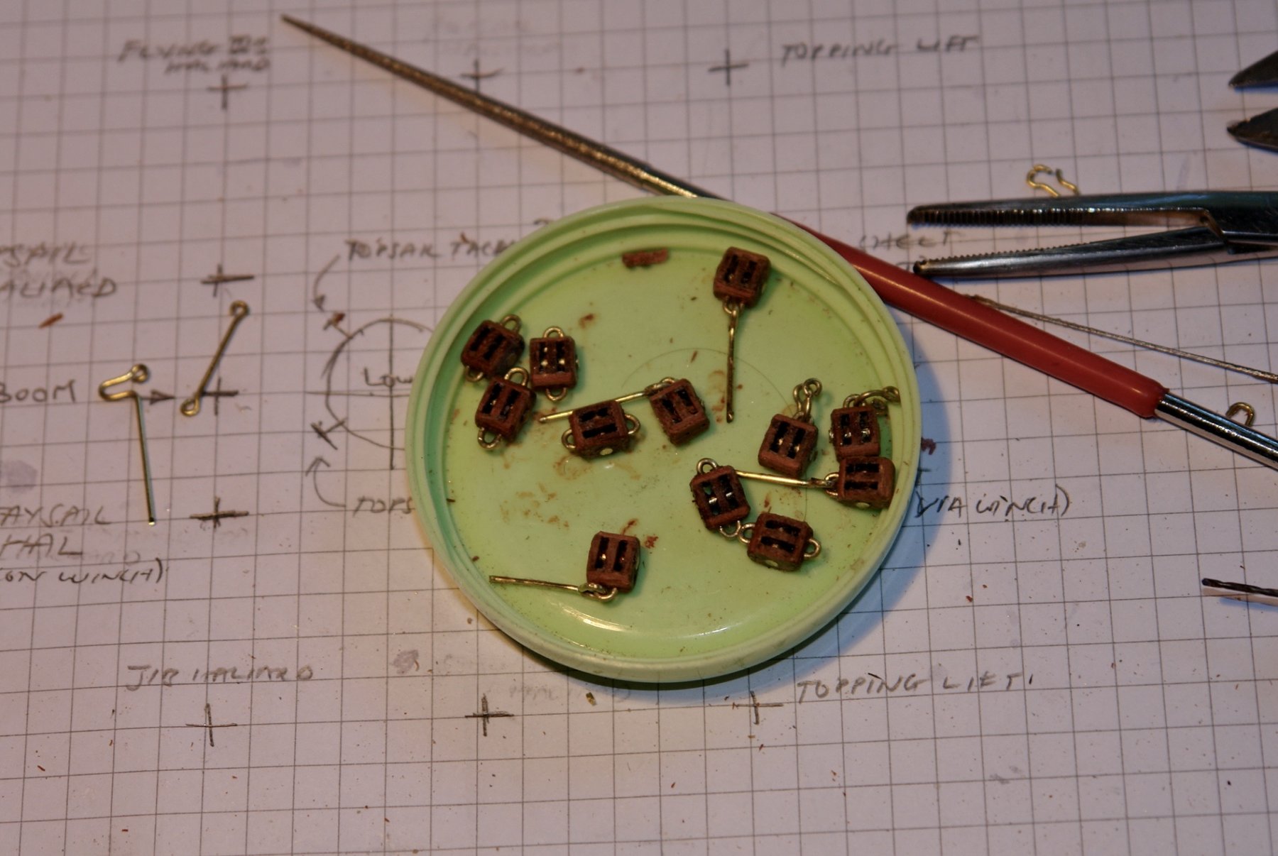
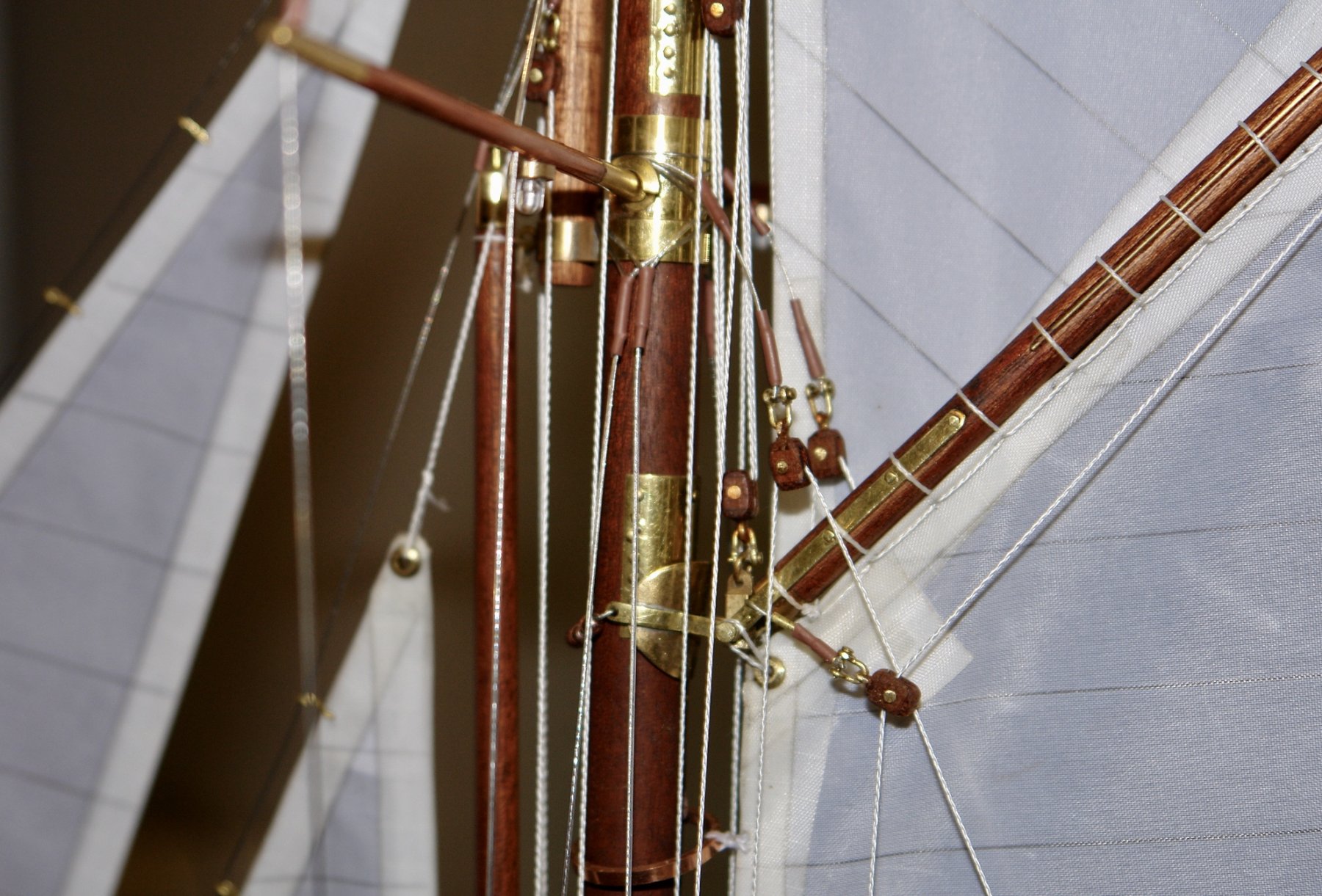
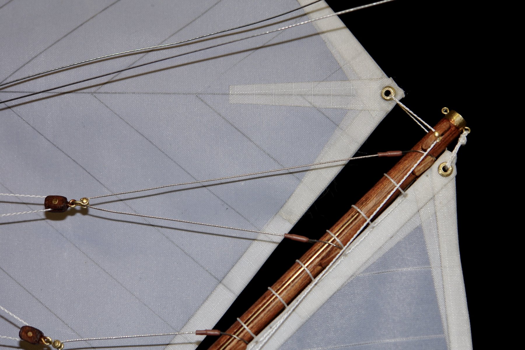
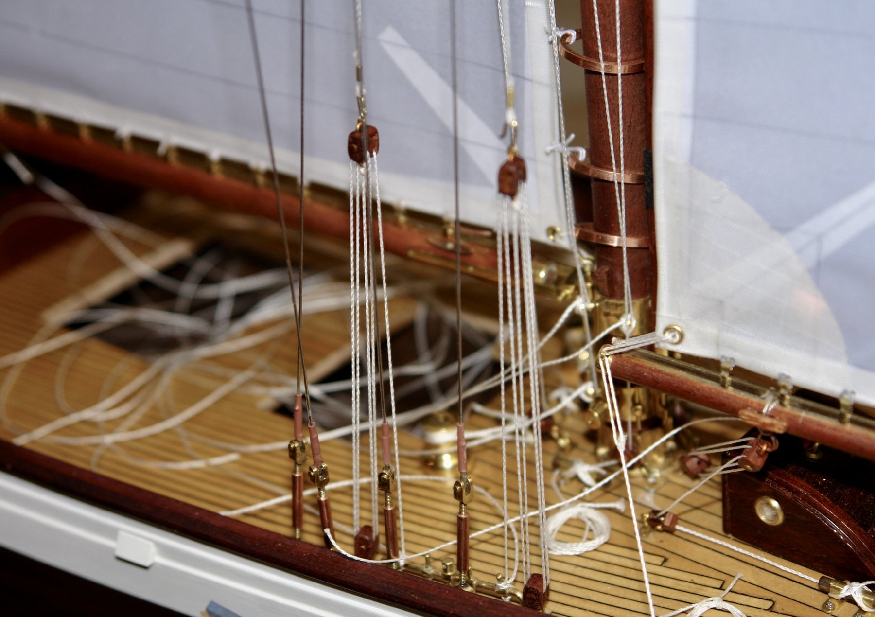
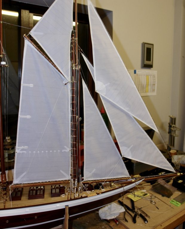
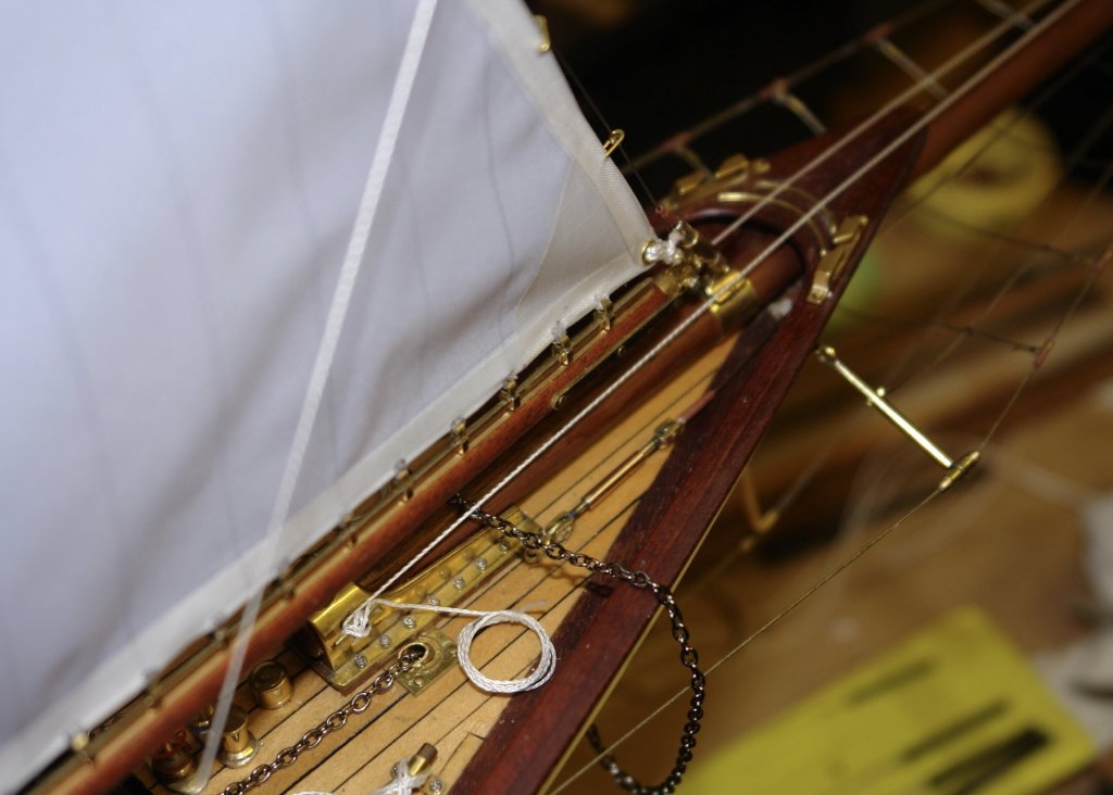
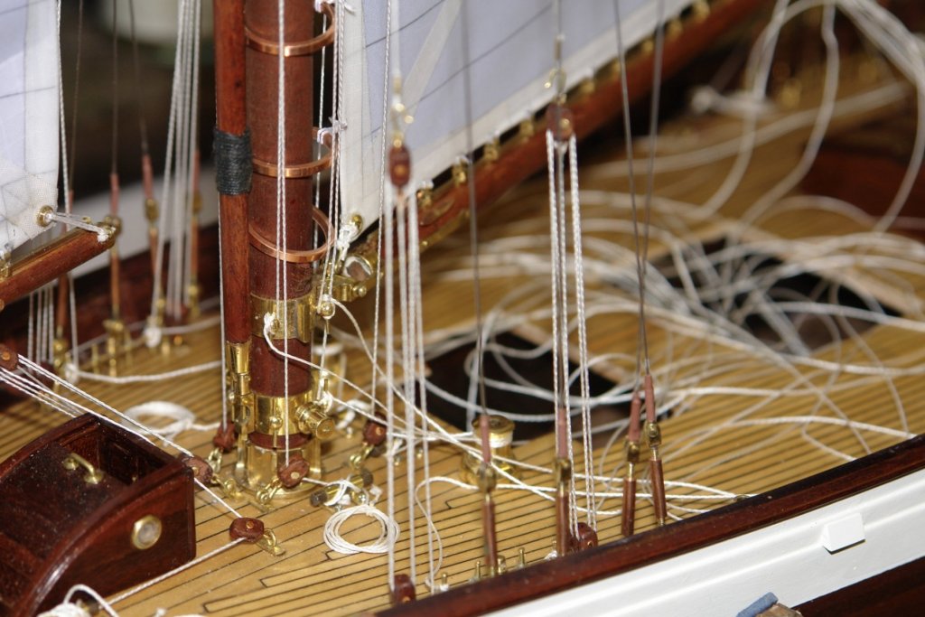
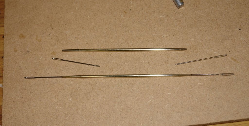
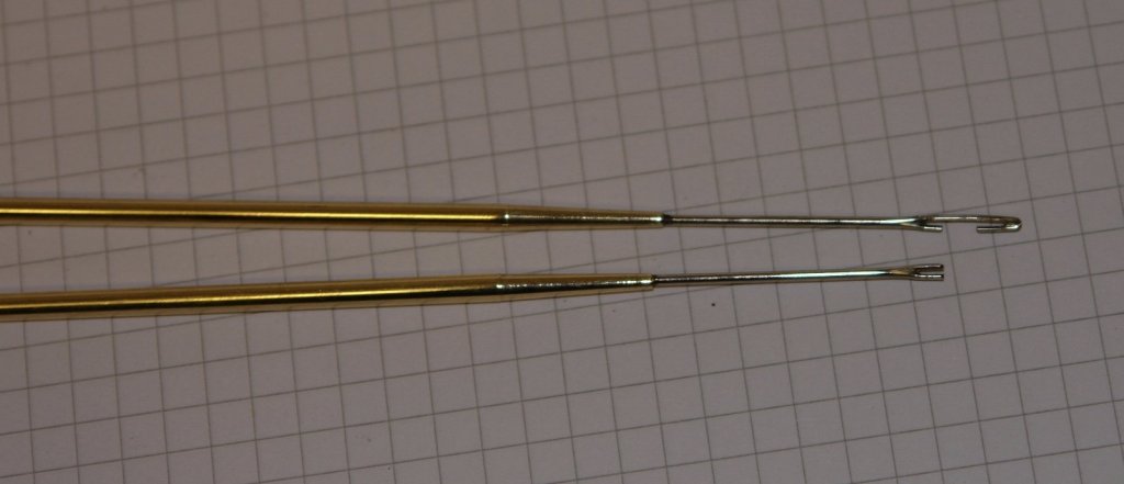
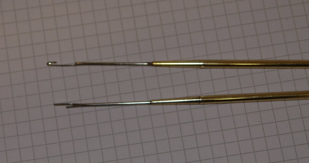
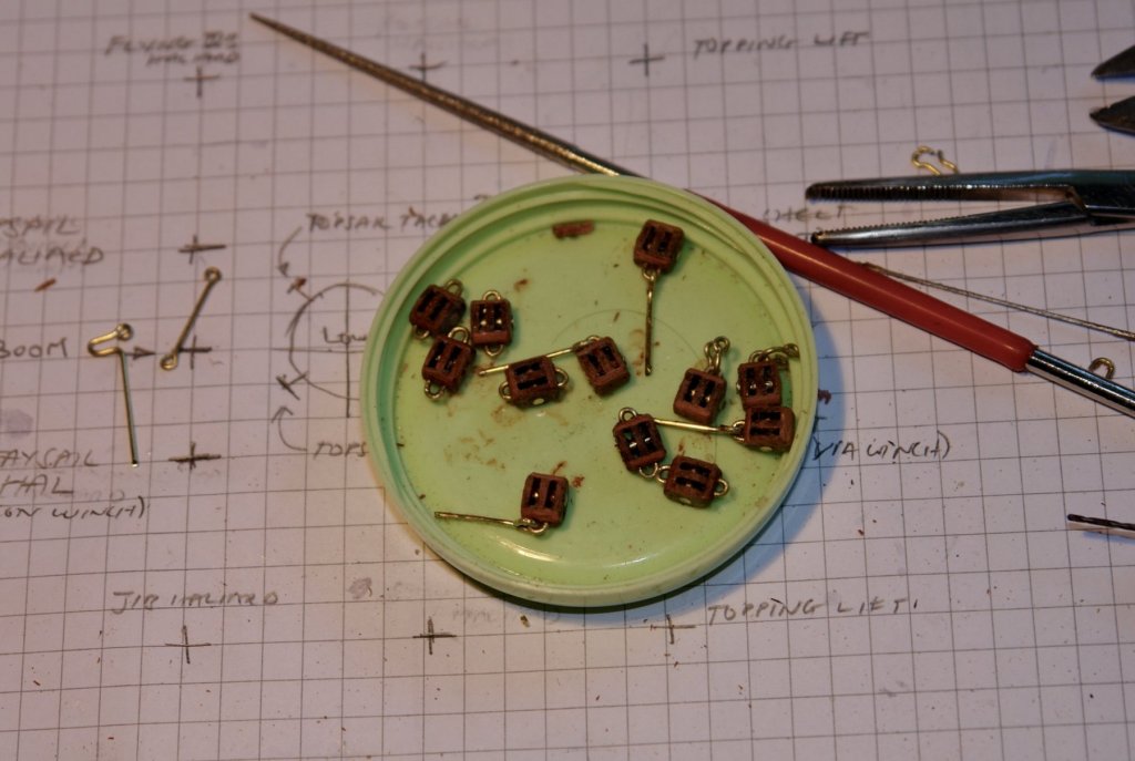
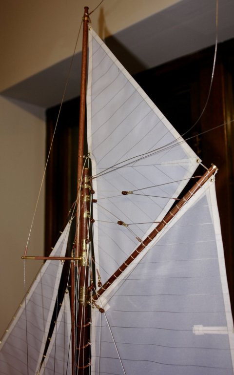
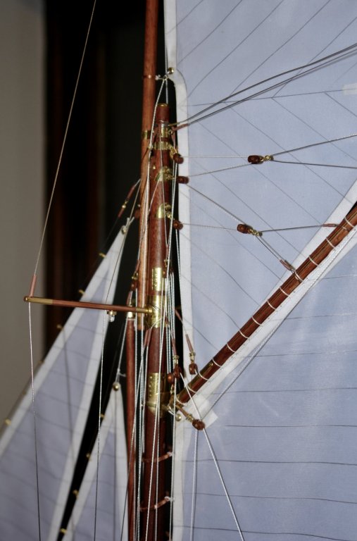
Nils / Frank Thank you for visiting and for your supportive comments. After a bit of a layoff I returned to sail making and rigging. The next step was the fore topsail. I took a while to sort out how the various sheets and halyards attached to the deck. The plans had rudimentary sketches of the mast and deck with the lines numbered to cross reference them. This would have been good had some numbers not departed the mast to be lost in the ether while others departed the mast as one line only to arrive twice at the deck. I decided the best bet was to generally follow the plan but make changes to create a sensible arrangement. My starting point however was to make some rigging tools out of 1/8" brass rod and sewing pins and a bit of solder. I am making blocks as I need them. I always seem to be needing a lot more! The fore topmast is triangular cut away at the luff to clear the lower mast The sail was made as previously described with wired edges. The sheets on the topsail are pass through sheaves at the end of the gaff, are led to blocks at the top of the luff, before going through blocks at the deck and on to deck winches. I was reading the Gaff Rig Handbook by Leacher which said this arrangement often blocks caused chafing of the sail. I reinforced the sail with patches behind the pulley (I would have done this if it had been my boat). See photo below. The topsail halyard and some of the other halyards are led to twin double blocks at deck level. Tacking of the topsail must be a real drag as its path is obstructed by a number of standing rigging and other lines. I suspect that it would have been set up correctly on the dominant tack and just allowed to sit inefficiently against the stays on the other. The alternative seems to be re-rigging the sail on every tack which seems to be a bit of a chore. Next I will move on to the flying jib.


- 882 replies
-
- 14
-
-
Please help! What to buy.
KeithAug replied to semorebutts's topic in Metal Work, Soldering and Metal Fittings
My recommendation would be use soft solder where you don’t need significant strength. This would mean 99% of a static display boat fittings. Solder paste is best for fine work. It’s more easy to control where you put it and hence less to clean off once the joint is made. Lead or lead free isn’t a big deal in my experience, I have never found much difference between either. Like Mark my preferred heat source is a small propane torch. The heat is instantaneous and you don’t need to touch the work to apply it. I use the torch for about 90% of my soldering work. I use a soldering iron only where I need to be really precise about where the heat is going, e.g. when making a series of joints in close proximity without the following joint melting the previous one. When the component to be soldered is thin (e.g. photo etched parts) a torch is likely to distort or melt it, in this case a soldering iron is better. A alternative option which is less aggressive than a torch but does not involve touching the work is a hot air soldering gun, many modellers swear by them as the soldering temperature can be adjusted facilitating the use of different melting point solders. I just use the same paste flux that I use for plumbing. It works fine. -
She is such a cute little boat. Such nice lines and a lovely build.
-
Hello John It was a bit of an informed speculation. A few years ago we sailed into the small port at the north end of the Greek Island of Kea. We moored stern to in the pack of boats which included a couple of very large motor yachts. After mooring my pal and I went for a walk along the quay. As we passed one of the motor yachts our attention was drawn by loud music and flashing lights. The yacht had a huge lounge, closed at the back by large bi-folding doors. These were drawn open revealing within a mega tv screen, bar, disco stage and dance floor. Arranged around the dance floor was an array of armchairs, loungers, and seating pillows. Prostrate on the furniture were several very large and balding Greek men dressed in Bermuda Shorts and shirts. As they smoked their cuban cigars and drank their martini cocktails their guts strained for freedom and were restrained from escape only by the herculean efforts of a few gallant buttons. On the dance floor, seductively swaying to cat strangled wailings of some latter day greek diva, were a group of scantily clad young women who were of varied ethnic and exotic origin. My friend caught my gaze with a knowing smile, but this was immediately dashed by my comment:- "Isn't it nice when grandparents give up their weekends to take their granddaughters on a nice cruise". Thank you for taking the time to follow my build and for your comments.
-
John In my experience the ladies you are talking about are more likely to frequent luxury motor yachts with twin 5000 hp diesels, a sun deck, sauna and swimming pool. More than likely manned by overweight and aging millionaires with fat wallets and a short expectation of remaining life.