KeithAug
-
Posts
3,986 -
Joined
-
Last visited
Content Type
Profiles
Forums
Gallery
Events
Everything posted by KeithAug
-

Hello all from Staffordshire England
KeithAug replied to Smudger2501's topic in New member Introductions
Hello Smudger DarkOps stuff looks like fun and should get you off to a good start. I look forward to seeing your builds. -
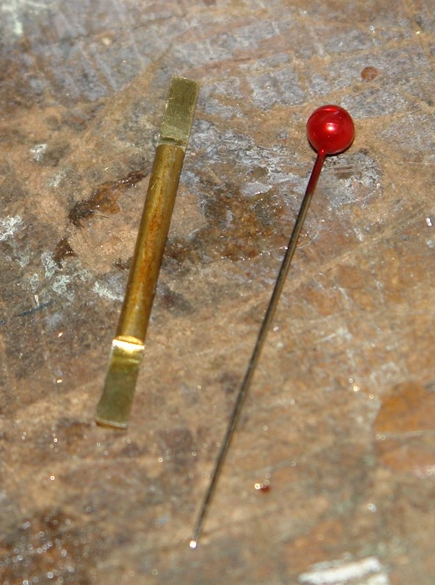
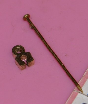
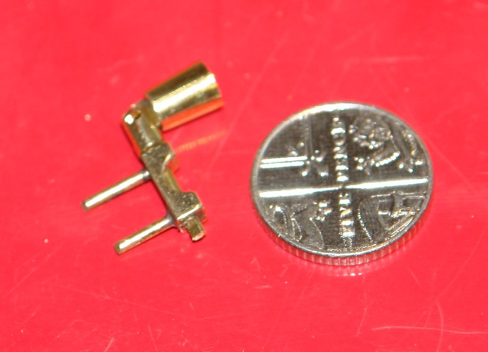
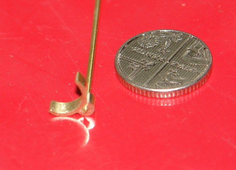
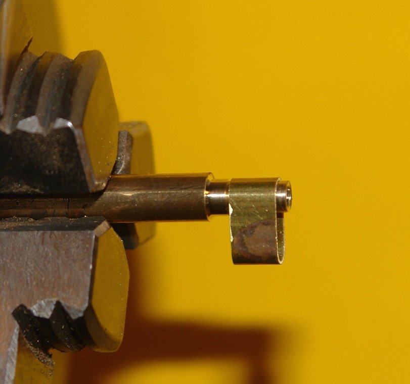
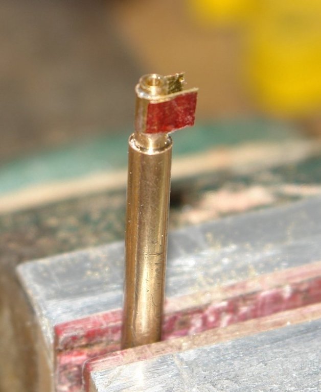
I bit the bullet and now have a slider. The pin is 3/4" long. The "T" of the track fits in the slotted hole and the sail attaches to the ring. I'm going to bed a little less daunted.
-
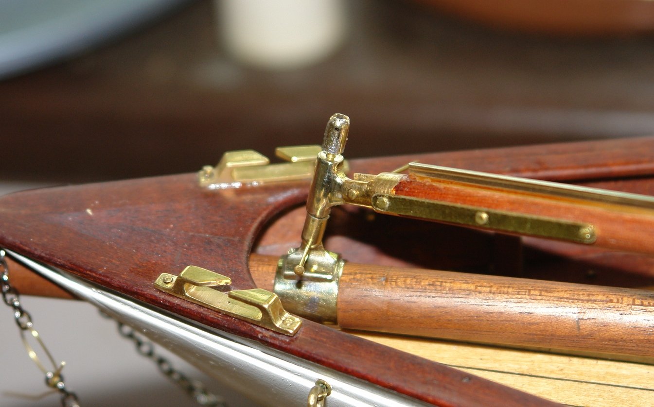
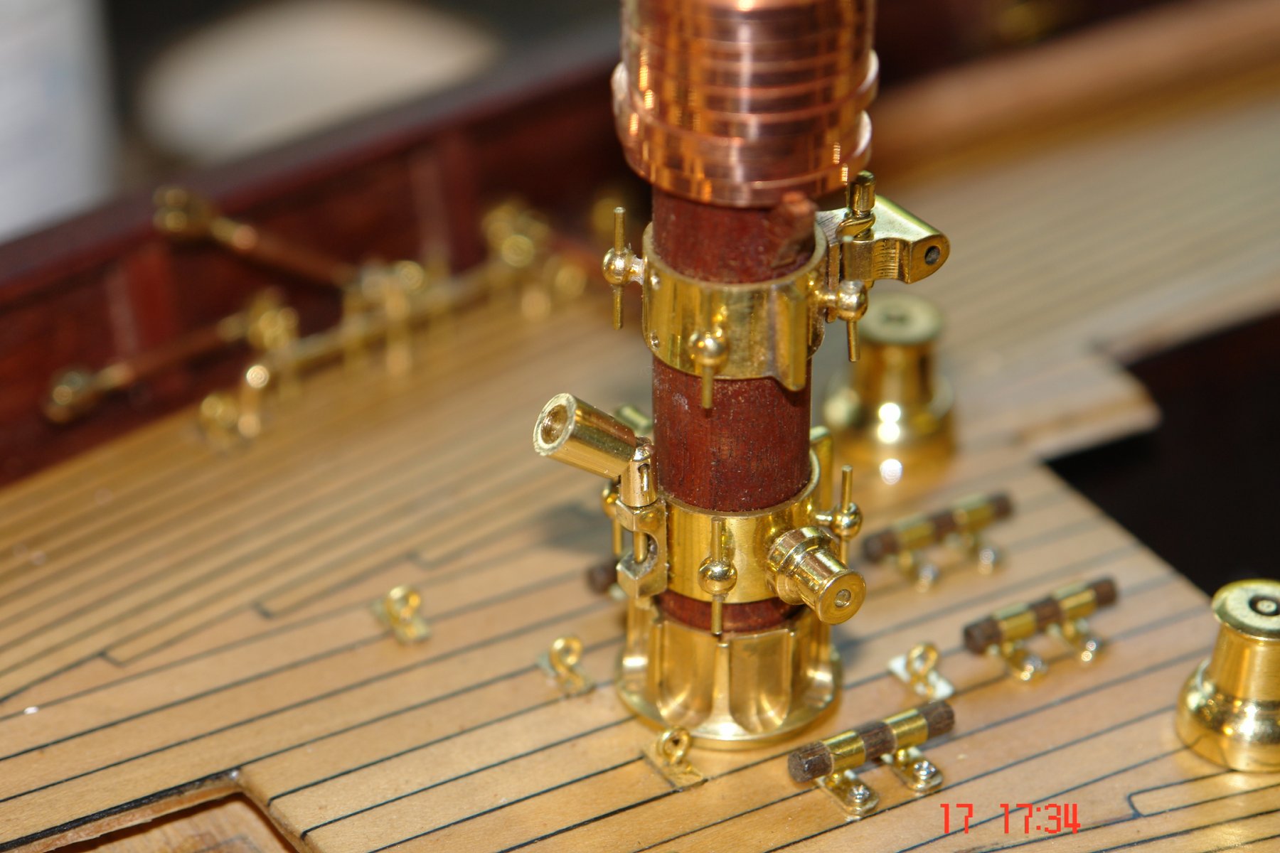
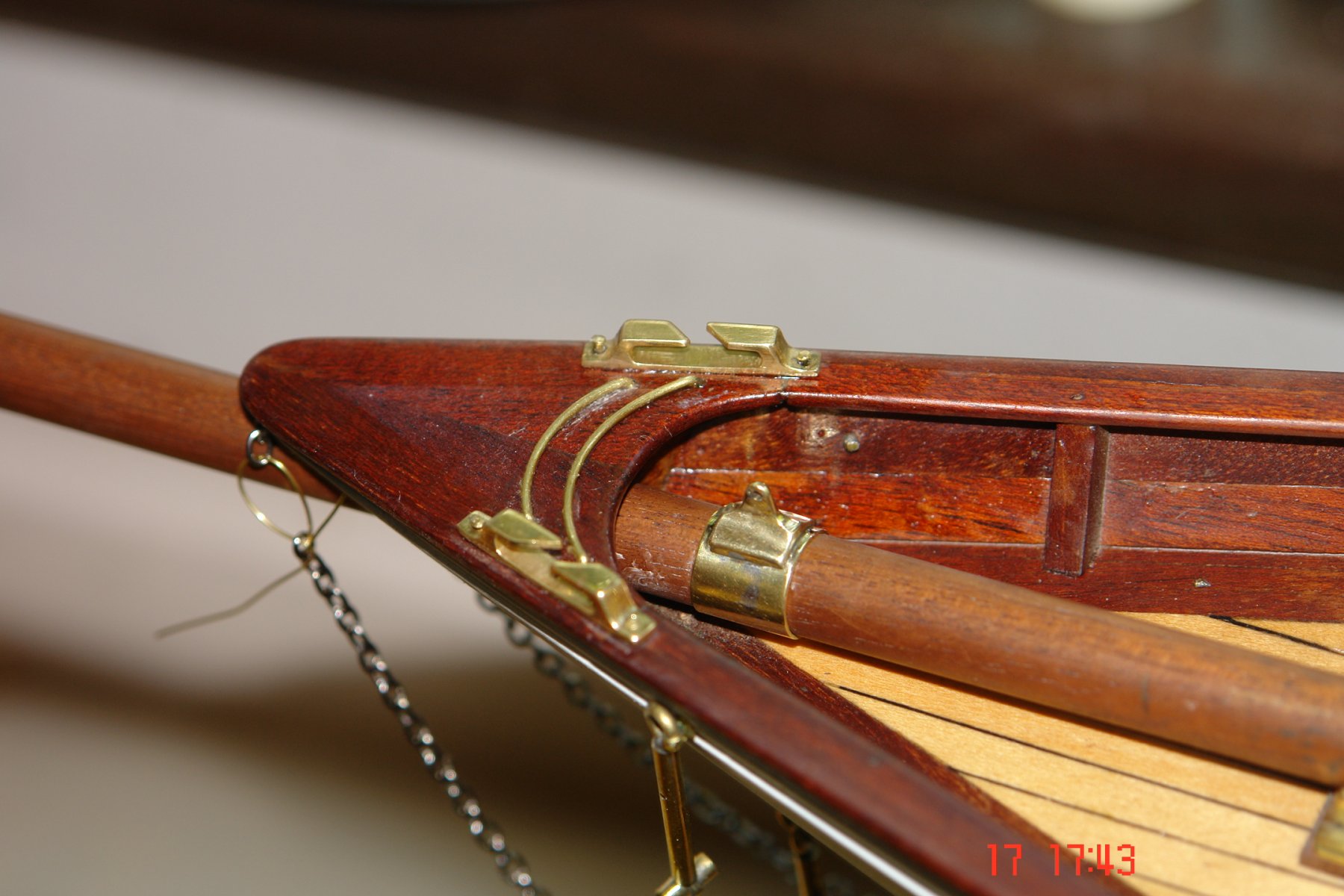
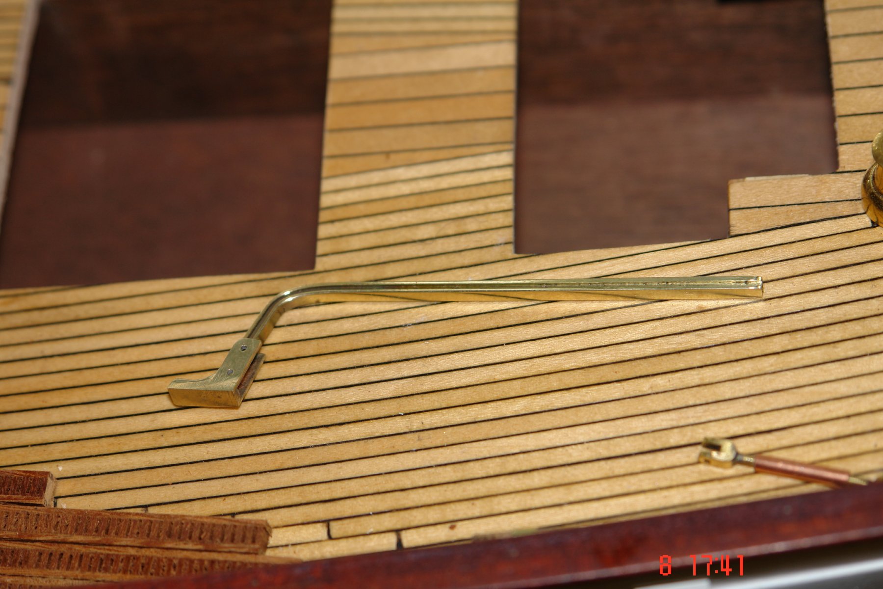
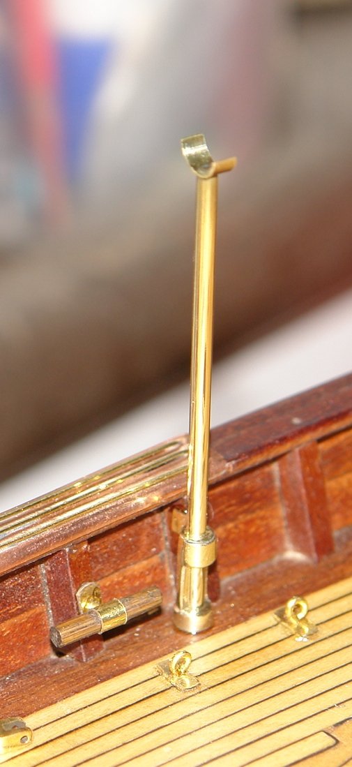
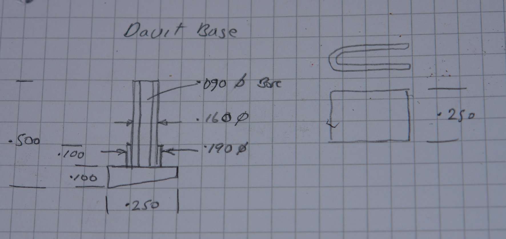
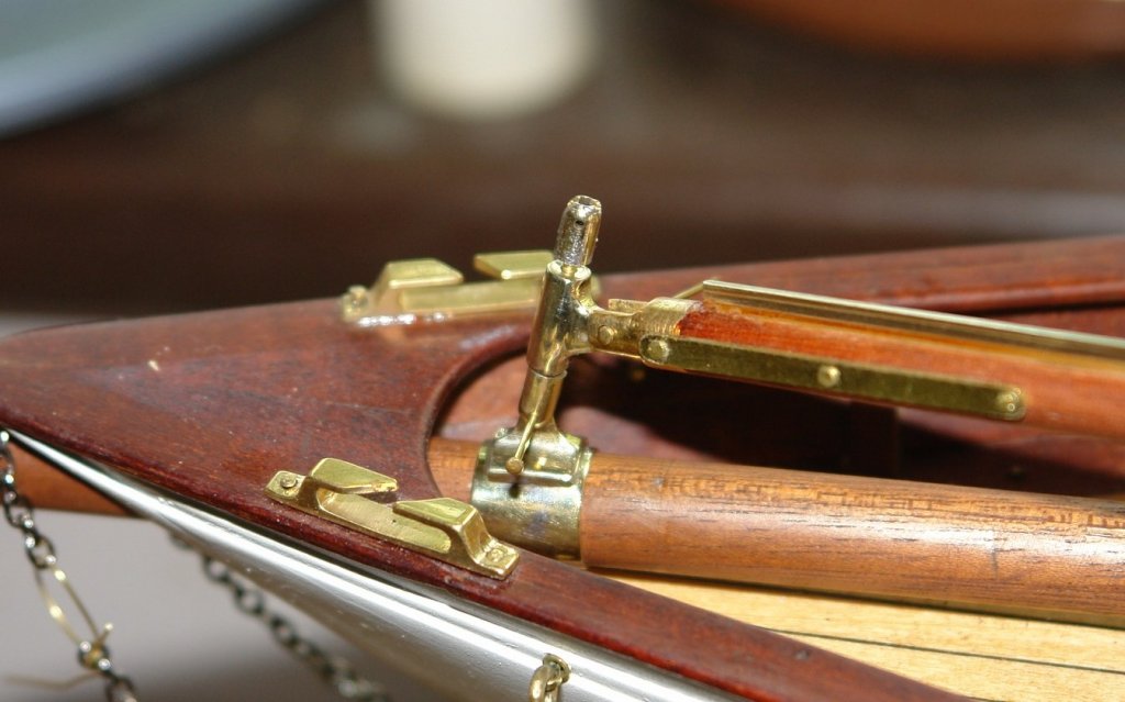
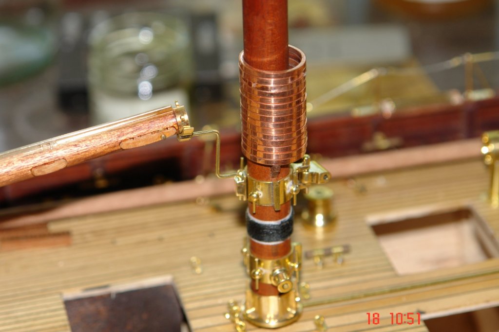
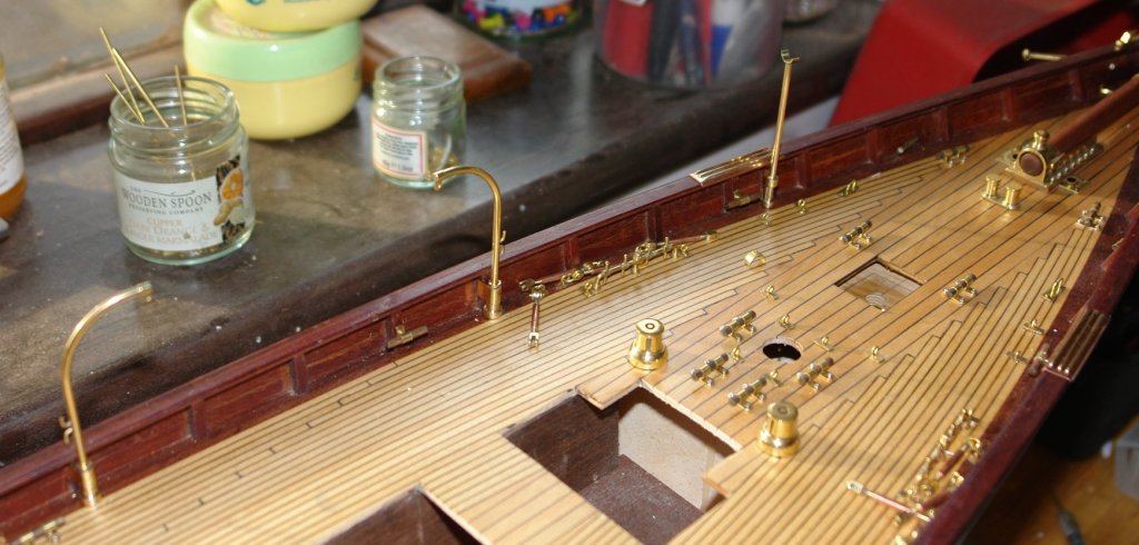
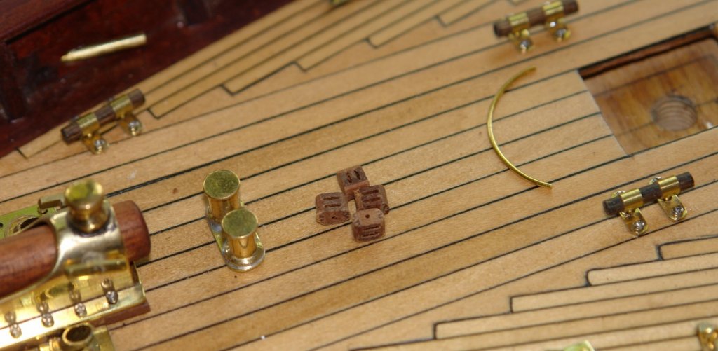
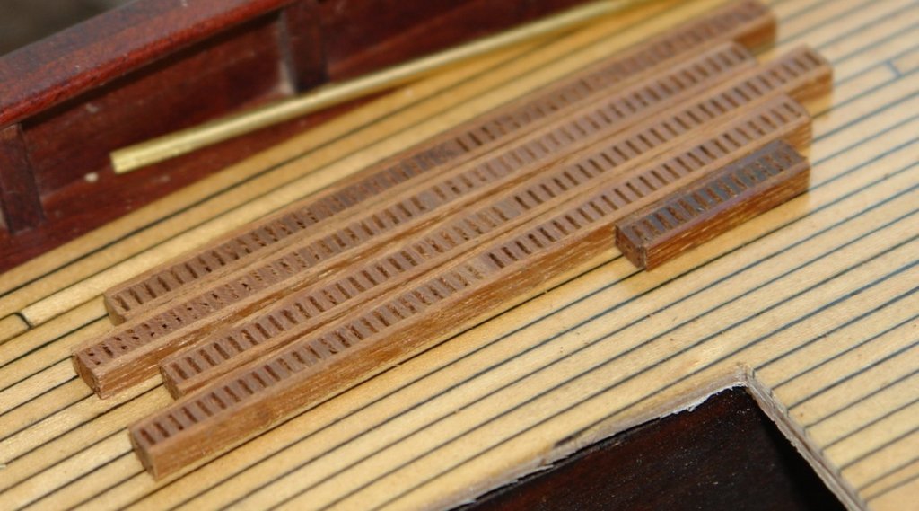
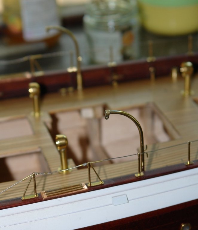
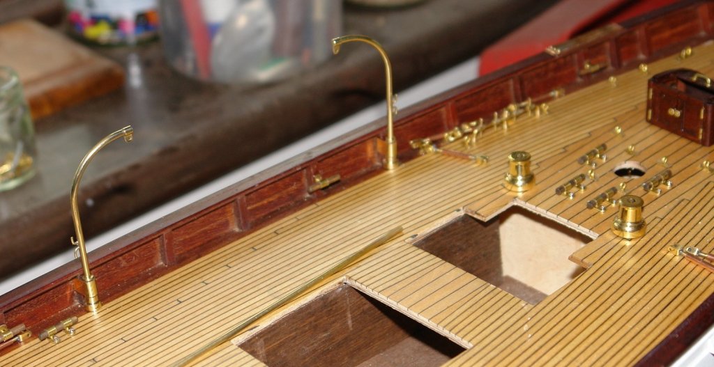
Michael, I now flip between metric and imperial quite naturally. I find that I quite like scheming out small parts in metric, which I usually convert back to imperial when its time for machining (my lathe and mill are imperial). I don't usually do the conversion very accurately, finding 1mm = .040" being good enough for most purposes. I try to use imperial when I post updates. Thank you for the anchor comment. I am coming to the end of the deck fittings, just mopping up the few that remain in an attempt to avoid getting on with making the 60+ sliders. Anyway here are a few bits: The mounting for the staysail boom. The gooseneck for the spinnaker boom - attached to the foremast. The rail protection at the bow. The foremast boom crutch - mounted on the main past. The semicircular support was made out of 3/8 inch tube with a 1/8" drilled bar (scalloped on one side) soldered on. The only deck fittings left are protective strips adjacent to the stern fairleads and the port and starboard navigation lights. And then its those pesky sliders.


-
Mark, John. Thank you for your interest and feedback, also thank you to.all who have visited. Tom, I started an engineering apprenticeship with Rolls Royce (Jet EngineDivision) before they packed me off to Univesity to do a Mechanical Engineering Degree. Thereafter most of my career was spent behind a desk pushing a pen. I had to retire to relearn how to make stuff.
-
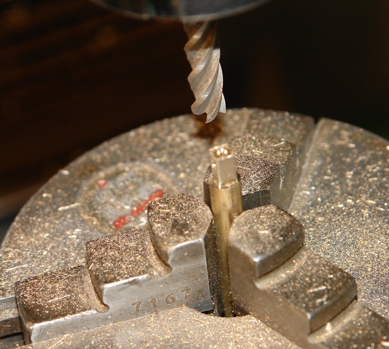
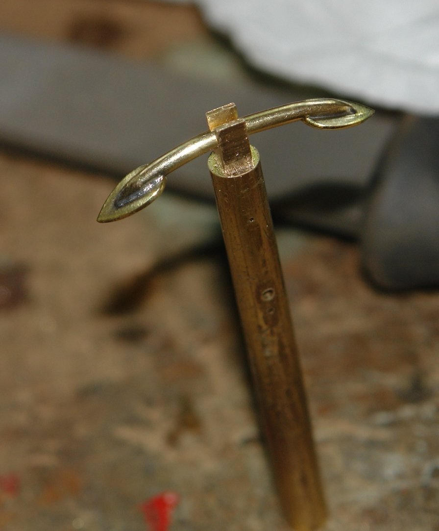
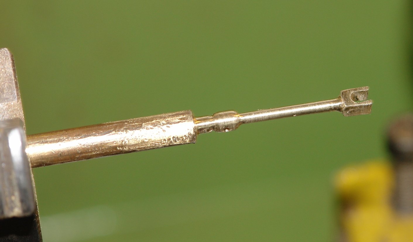
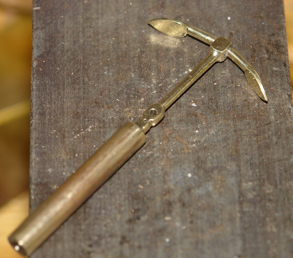
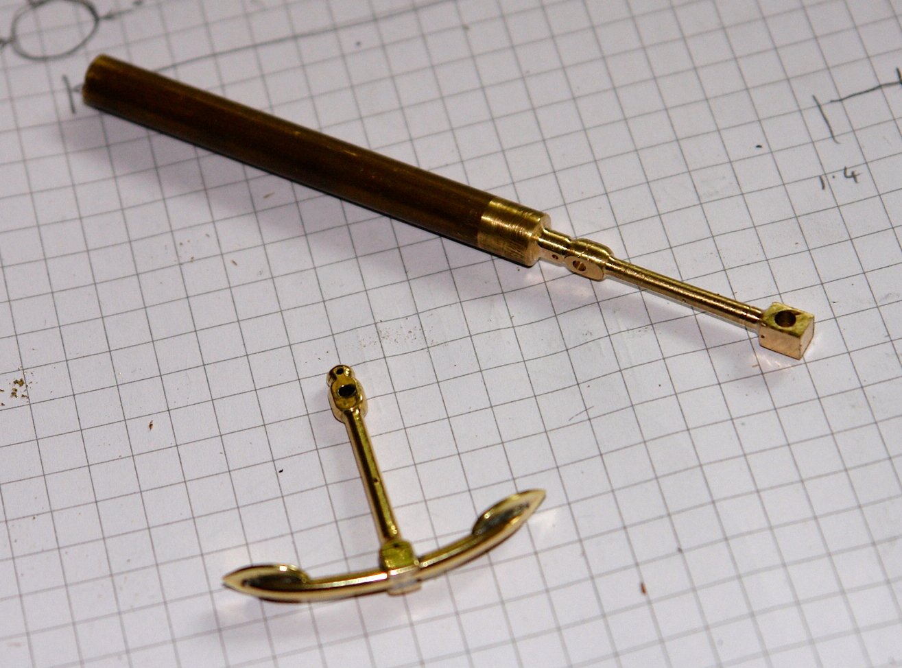
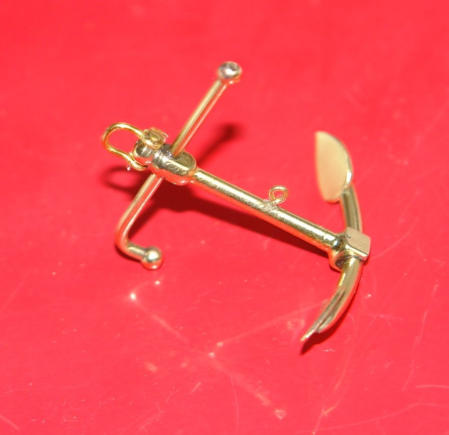
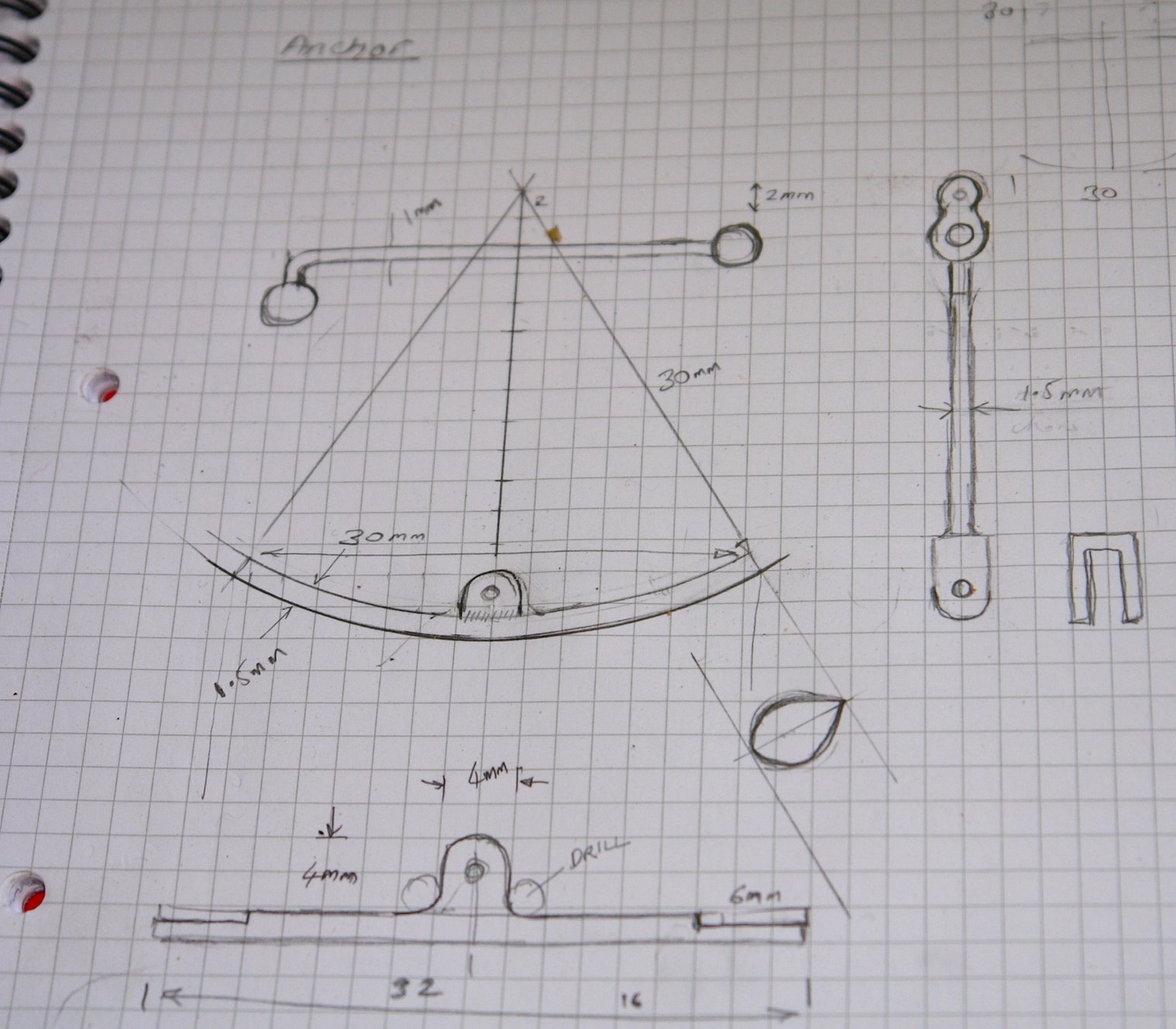
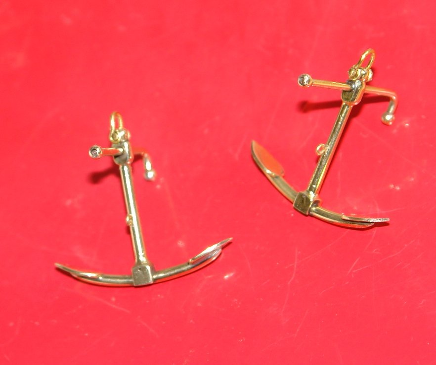
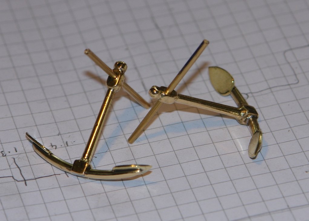
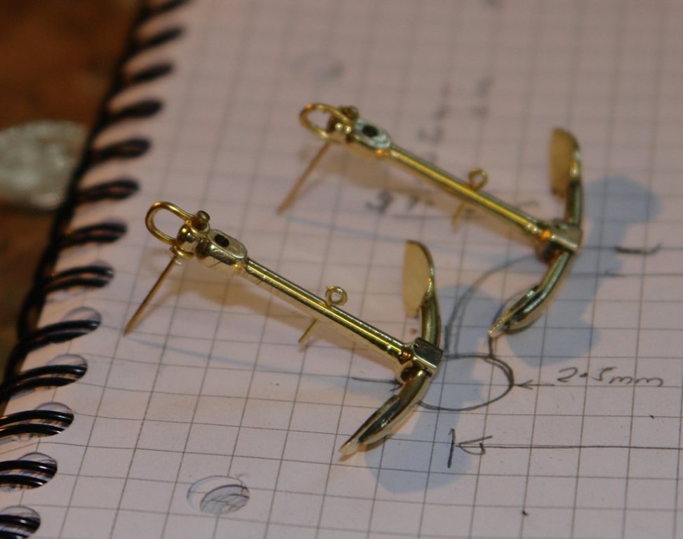
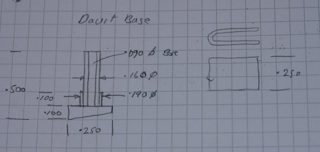
Bedford - thank you. So to continue with the anchor build: I did a bit more sketching to define the shank. I made the shank from 1/4 inch round bar. I initially drilled the various holes along the centre line and then squared off the end to form the bracket which joins the shank to the arm. The bar was held vertically on the rotary table and the square was cut with the side of the end mill. The slot was cut with a jewellers saw, cutting down to the the previously drilled cross hole. The bar was then transferred to the lathe and turned down to the appropriate diameters. The bar was then transferred to the mill and flats were machined where the stock passes through. The arm and shank were then soldered together. The anchor was then separated from the bar and polished up. The stock was made from 1/6 inch wire and the ends were turned down to mount the spherical balls (brass beads). The bead on the angled end was soldered on before the shank was passed through the stock and soldered in place. The final ball was then soldered on. I used toolmakers clamps to ease handling during soldering. Finally I mounted the handling eye and shackle - made from wire. For a distraction I made the ships bell - sometimes I can't be bothered with profile tools so I improvise turning the lathe saddle and cross slide hand wheels in unison to create the desired shape (sometimes with more success than others).


- 882 replies
-
- 10
-

-
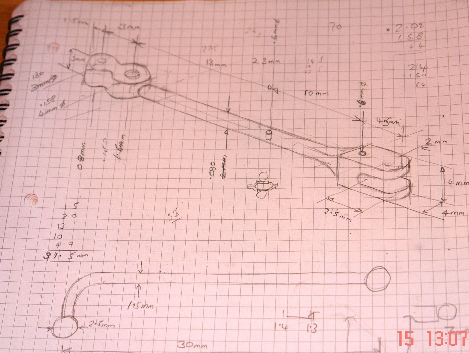
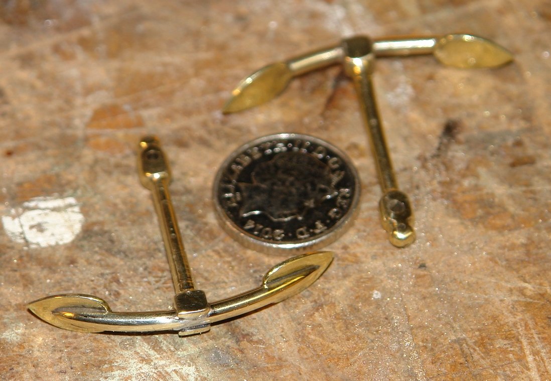
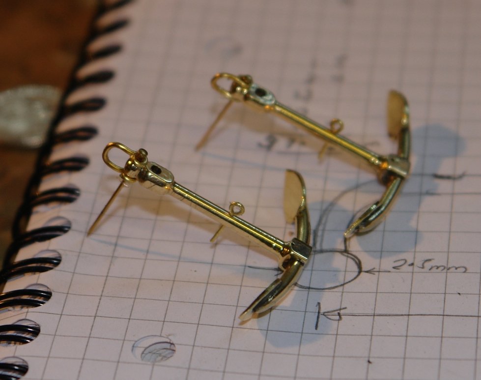
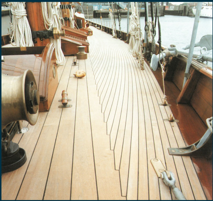
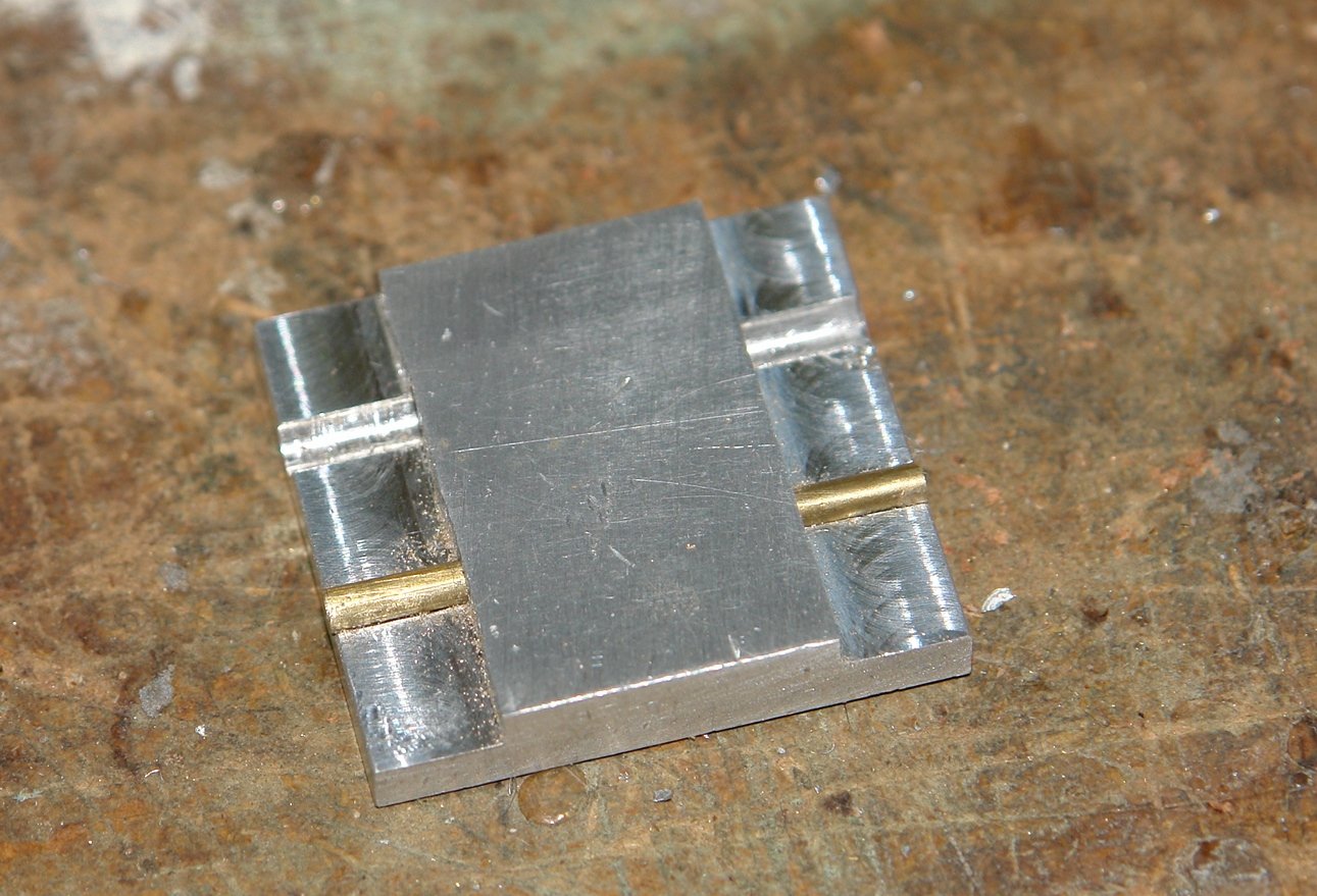
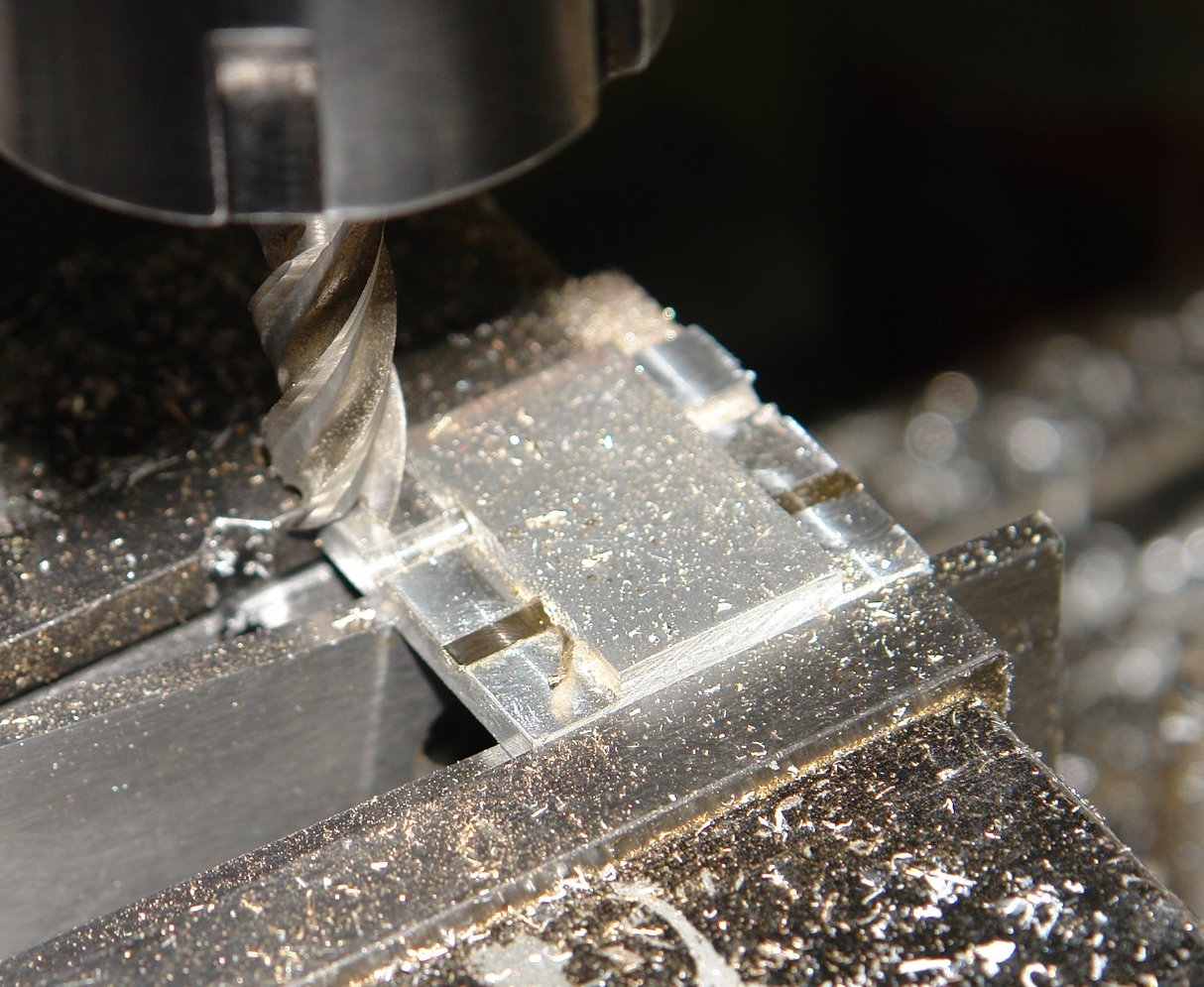
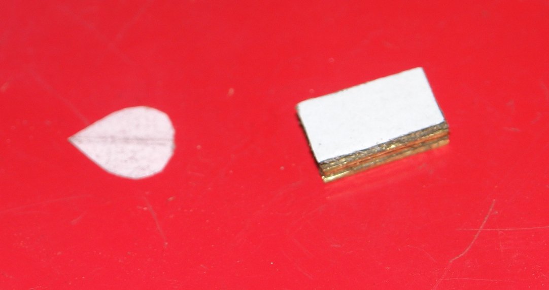
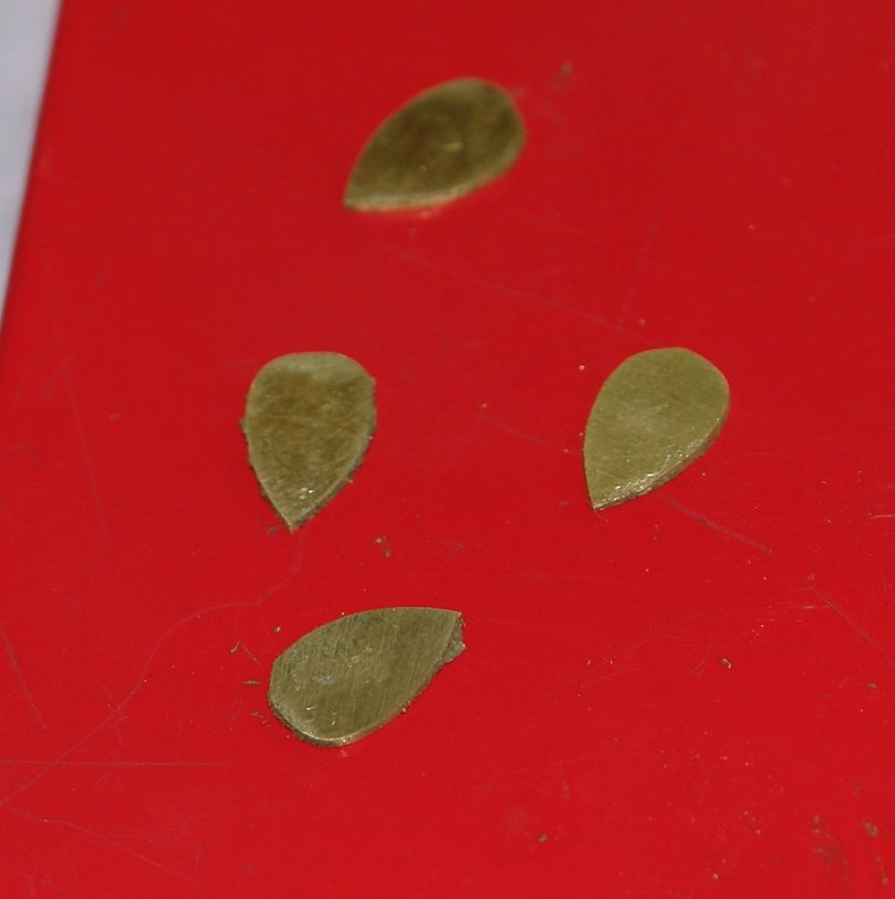
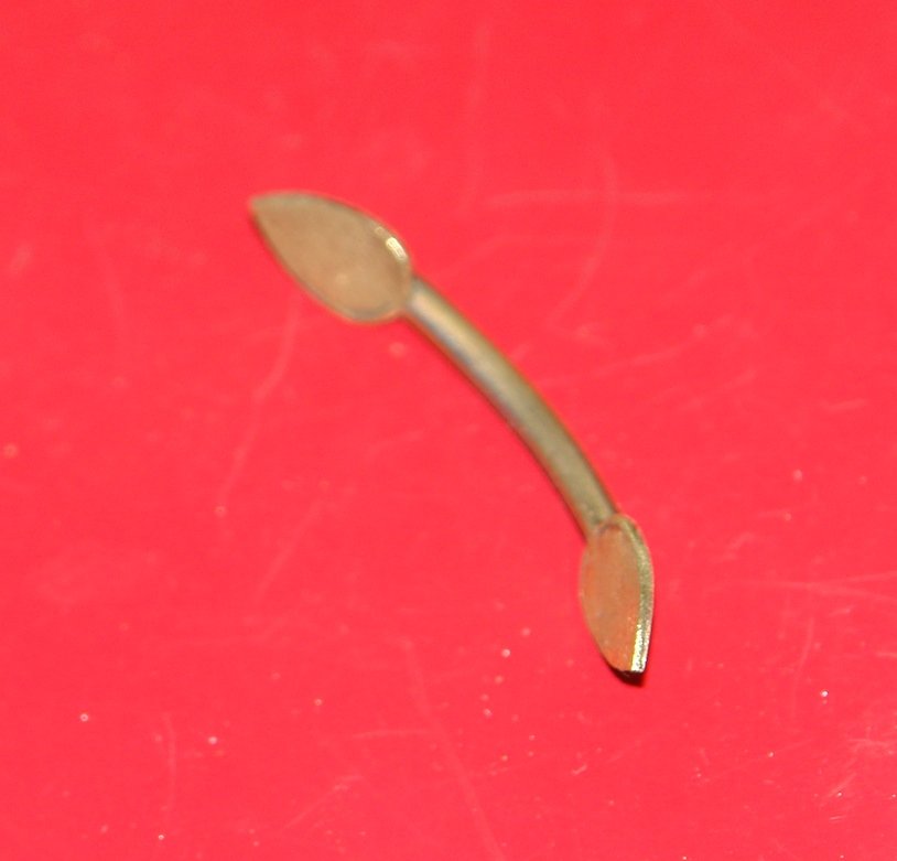
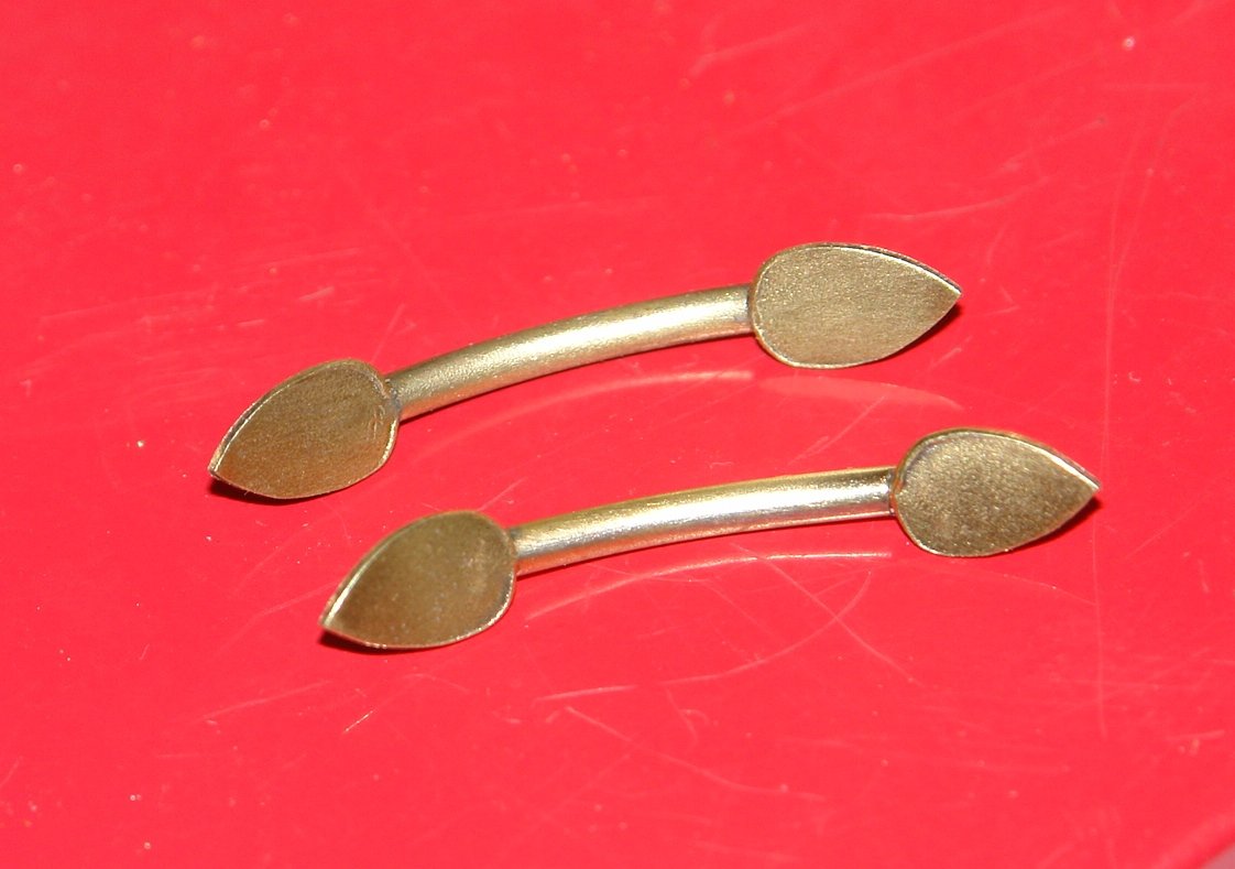
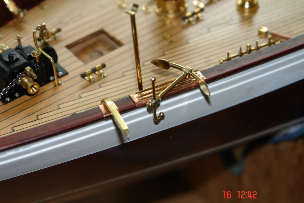
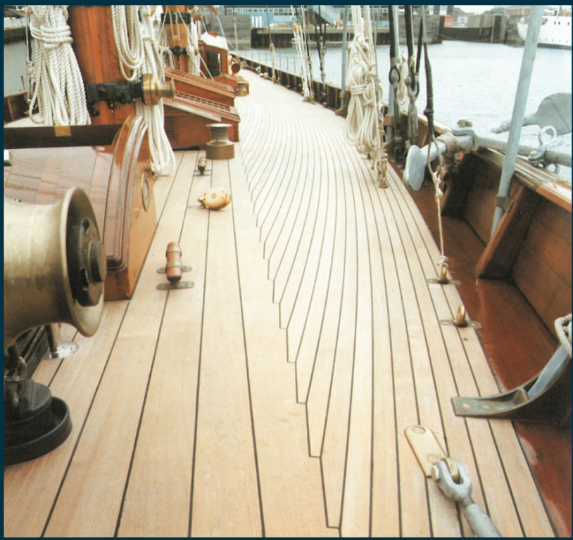
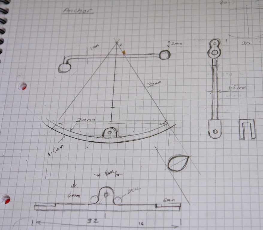
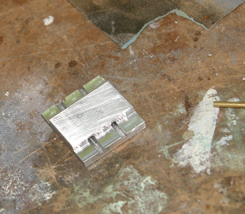
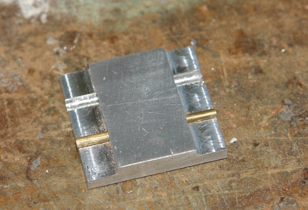
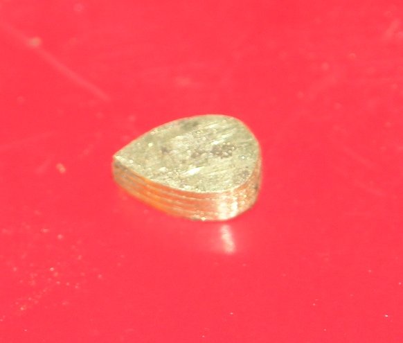
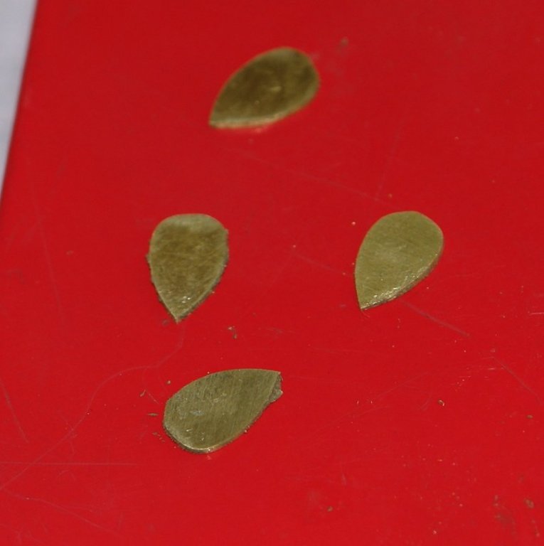
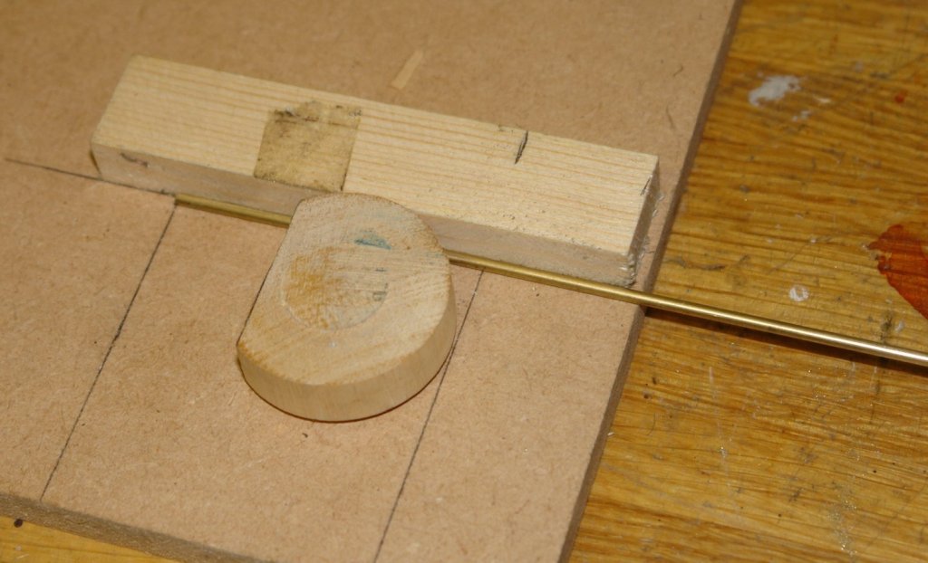
Michael, thank you. i'm looking forward to hear about the development of your new workshop. And so to continuing the build: I decided to have a go at the pair of fisherman's anchors which sit on the rail. I'll start with a couple of images showing how far I have got and then go back over the method. This may take a couple of posts. The anchors are a little under 1.250" high. I had fairly little to go on. The plan dimensions and details were rudimentary but I did have a partial image of the anchor on the rail. I started with a sketch which mapped out my initial thoughts. I modified it a bit as I went along. I started with the arm and the flukes. The arm was made out of 3/32" brass rod with recesses cut away at each end to take the flukes. Milling flats on slender rod required as simple holding jig made from a piece of scrap aluminium. The brass was cut to length and glued with CA into the jig to support it while milling, I heated the jig with the blowtorch to remove it. The flukes were made from 1/32" brass sheet. 4 square blanks were initially cut and then held together with double sided tape. A template of the fluke (which was about 1/4" long) was made by folding paper and cutting the half profile by eye. I had a few goes before being happy. The fluke "stack" was then shaped by jewellers saw and file. If I had to do it again I think I would cut the profile from a solid bar and then slit off the individual flukes using the slitting saw. I assembled the flukes and arm with the arm straight. To hold the components in position while soldering I clamped the 3 pieces to a thin steel strip - slightly bowed to provide spring clamping. Once soldering was complete I cleaned up the assembly on the brass brush wheel on my polisher. I found an old bit of dowel the right diameter to act as a former for the bending. The initial bend was by thumb pressure followed by gently tapping with a hammer. I had annealed all parts before soldering to make the bending easier. I'll stop now and pick up the story again tomorrow.


-
Mark & John - Thank You. Tom - fellow builders are always welcome to call in. Coventry is about 140 miles away but it is blocked off from West Sussex by a black hole called the M25 London Orbital Motorway. On a good day the journey time is about 3 hours and on a bad day time is warped and swallowed without trace. Thank you for your comments on my log, enjoy your trip.
-
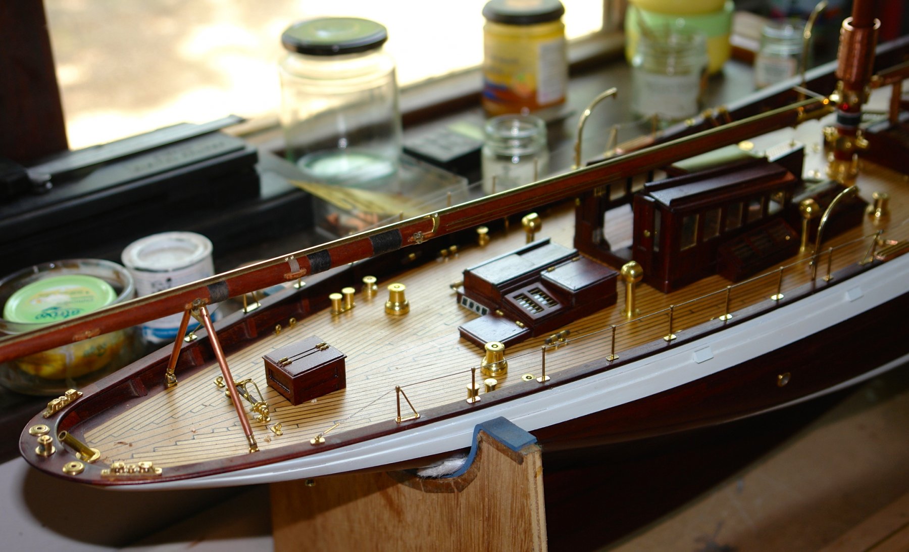
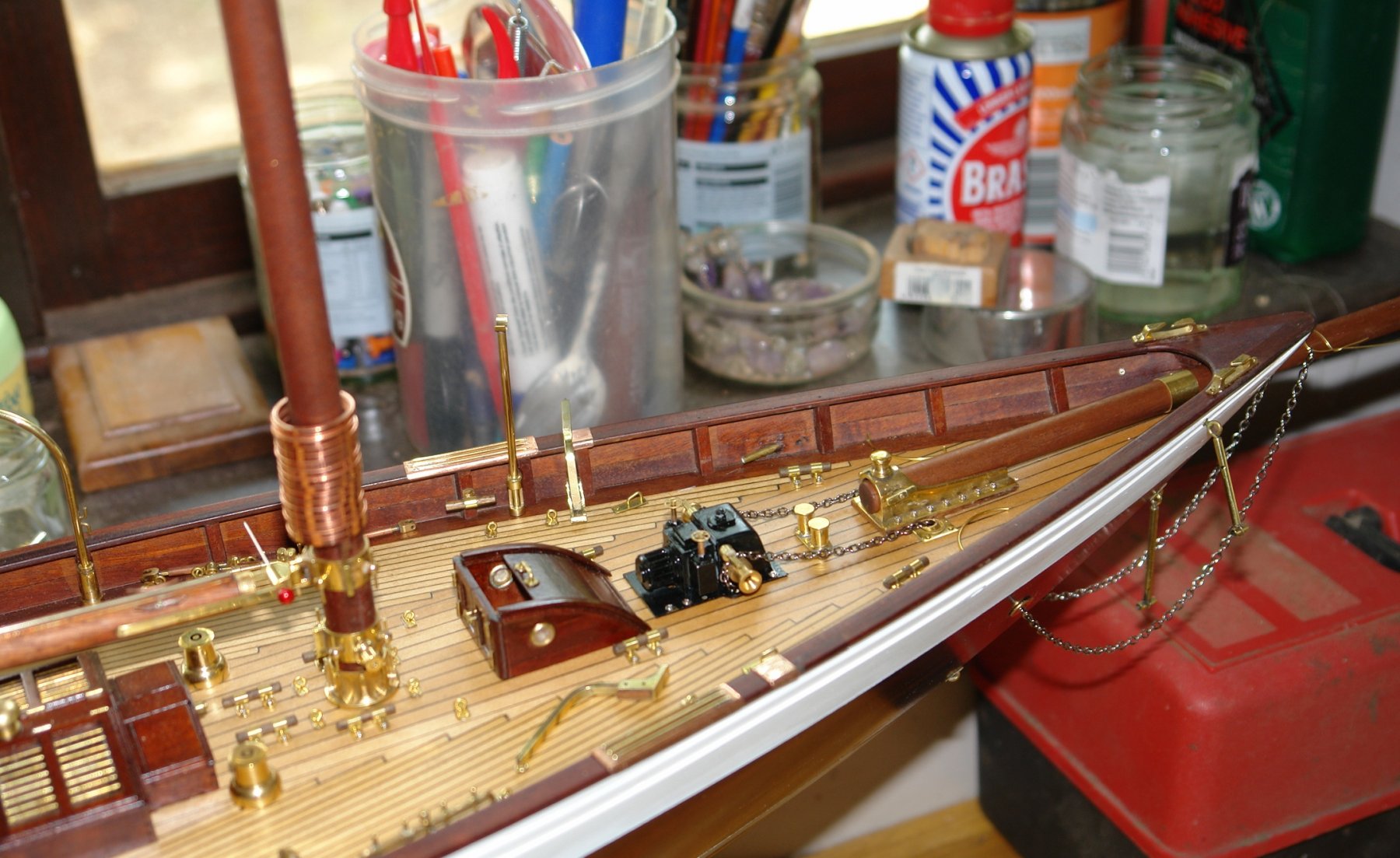
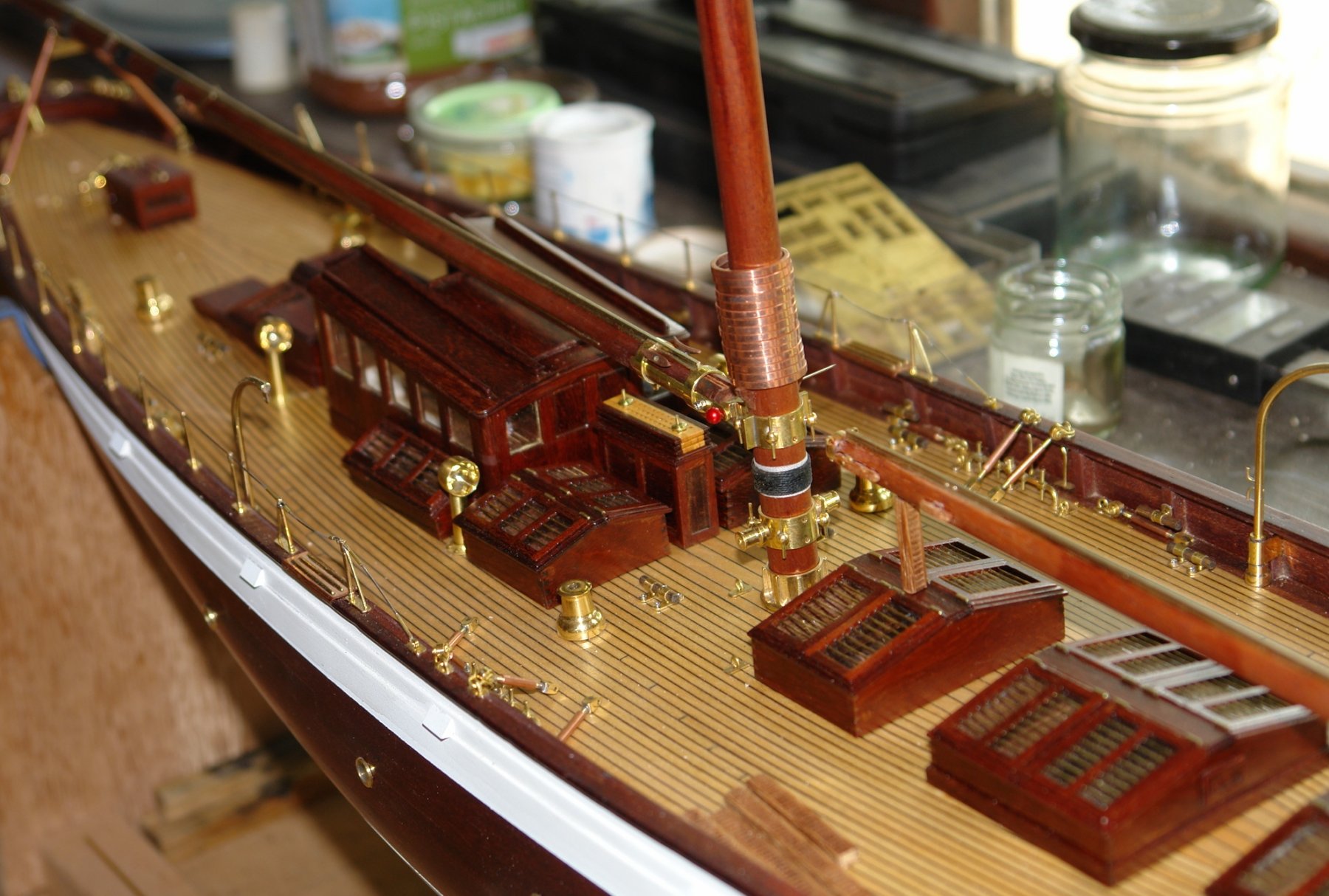
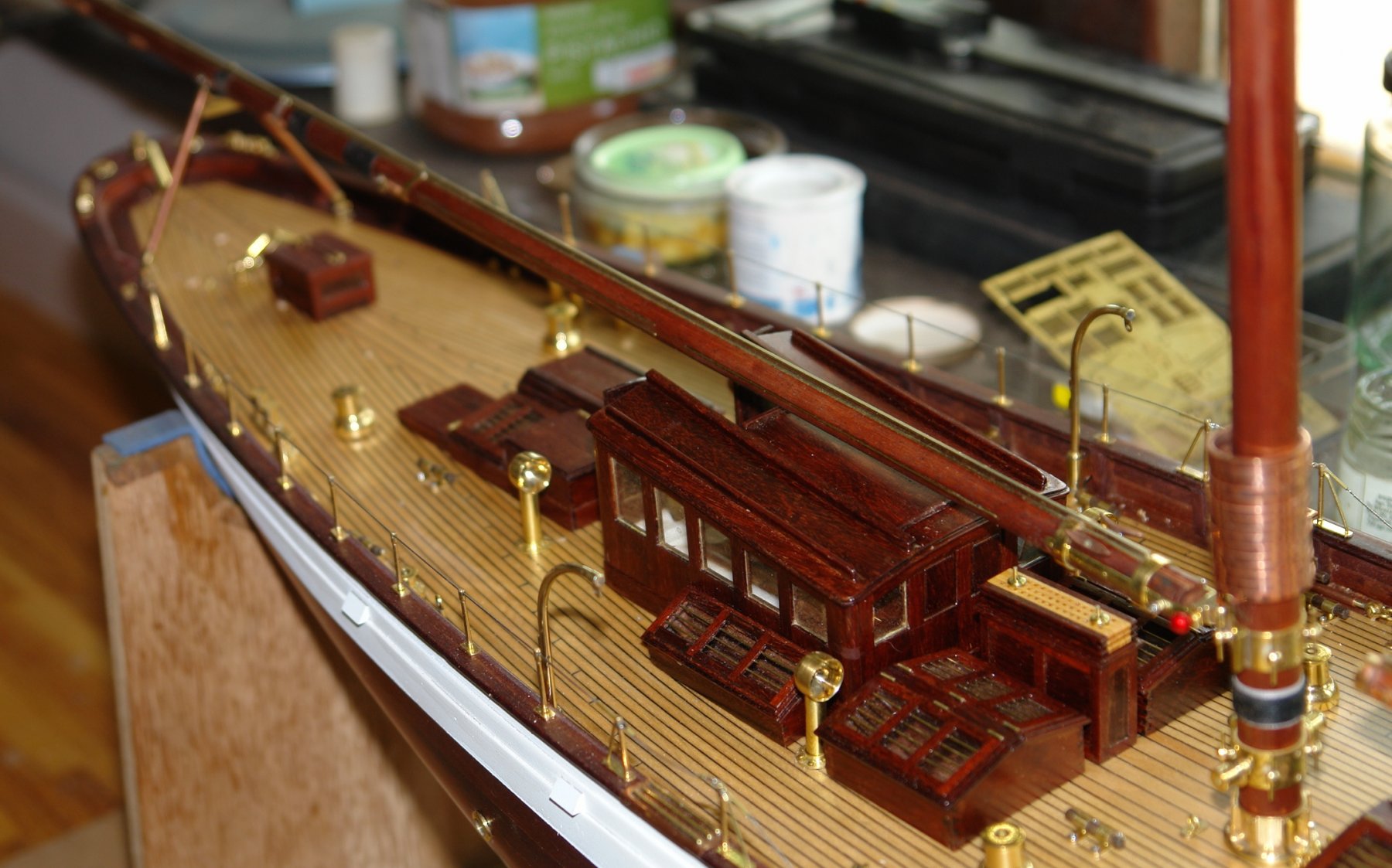
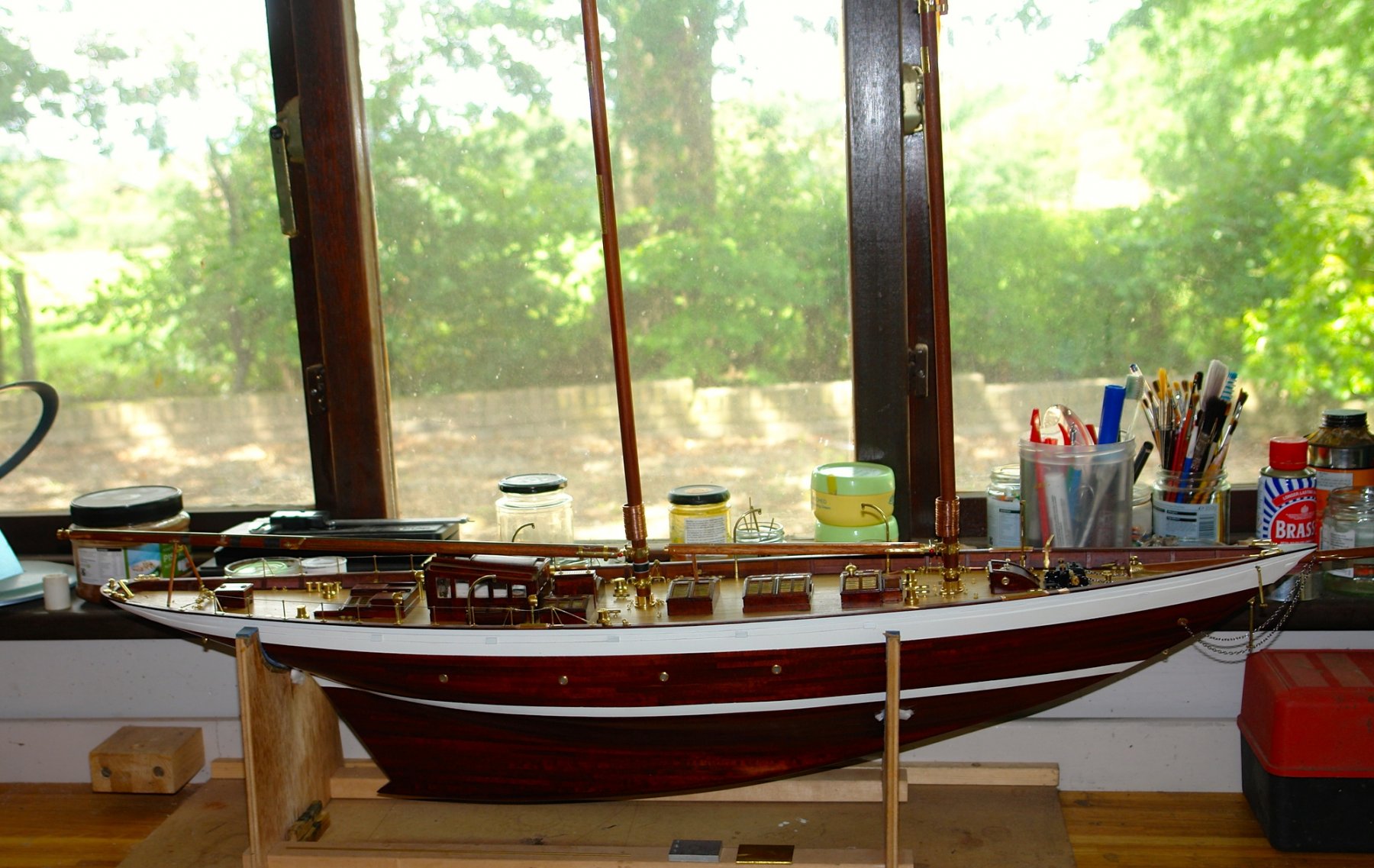
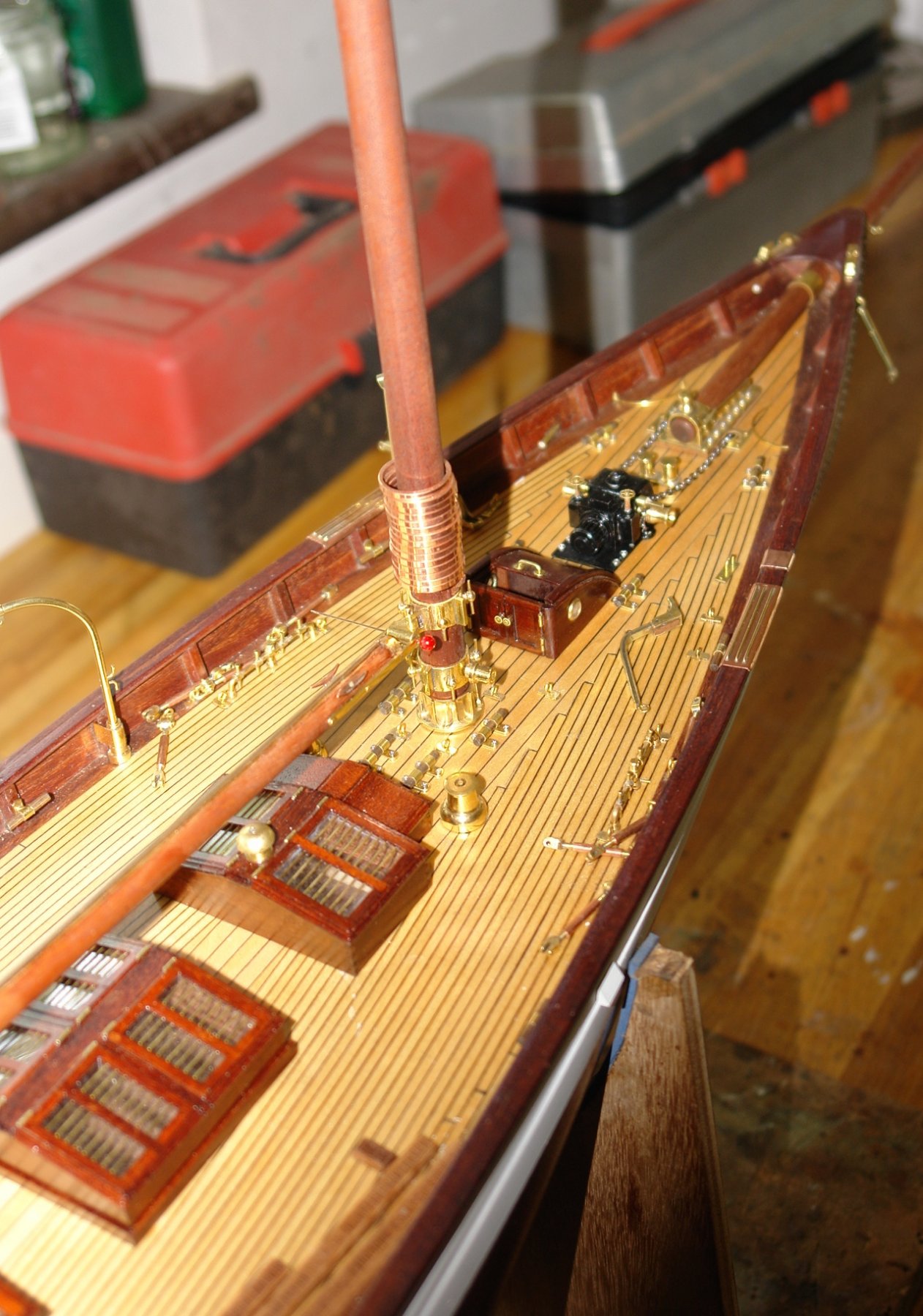
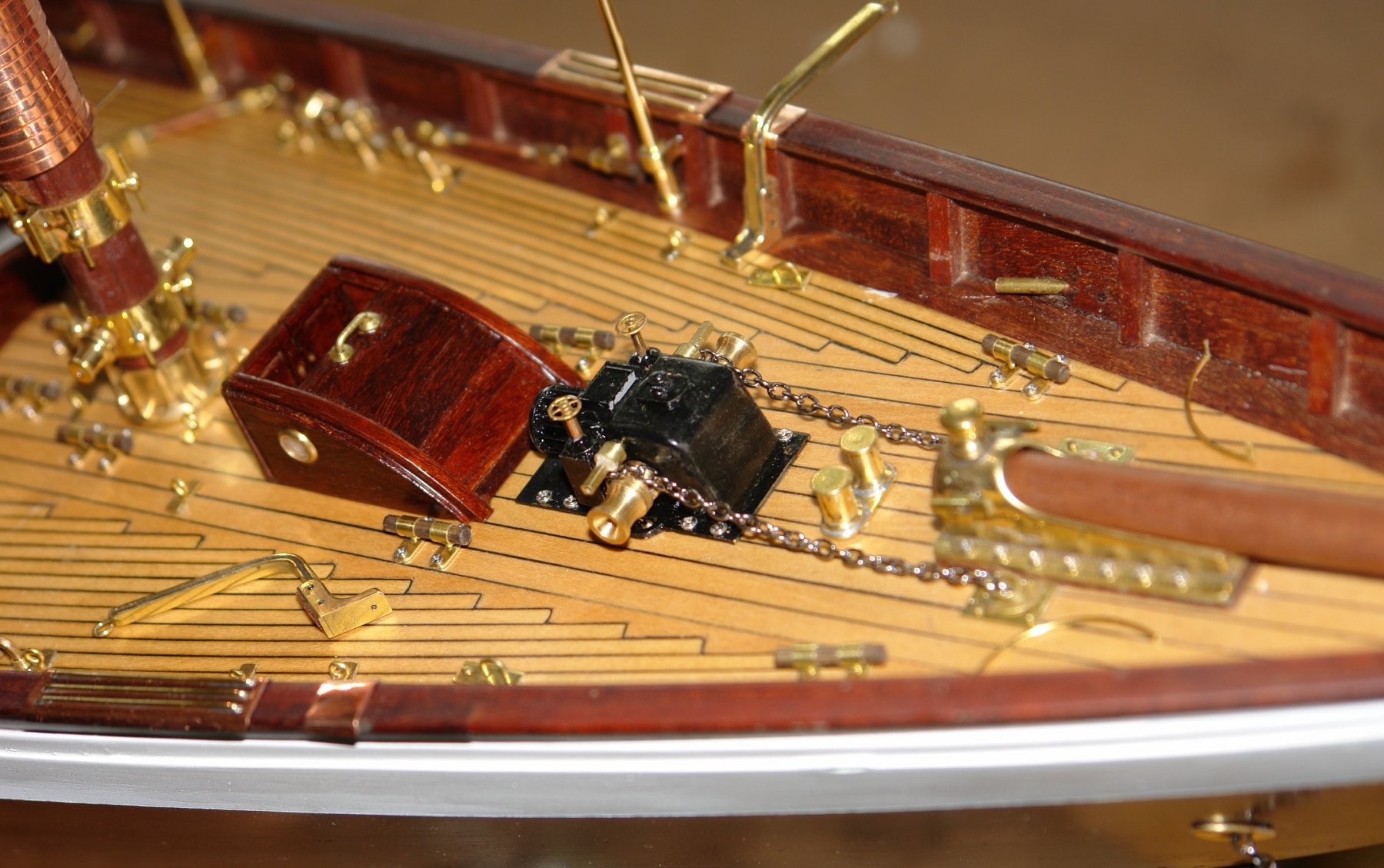
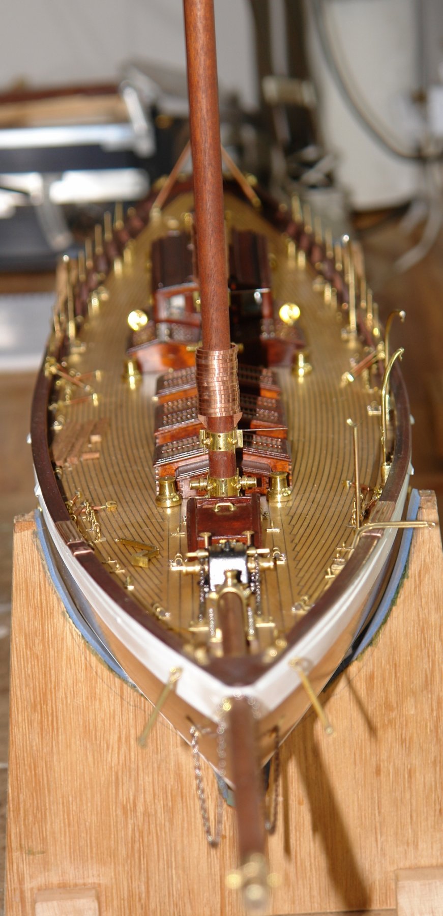
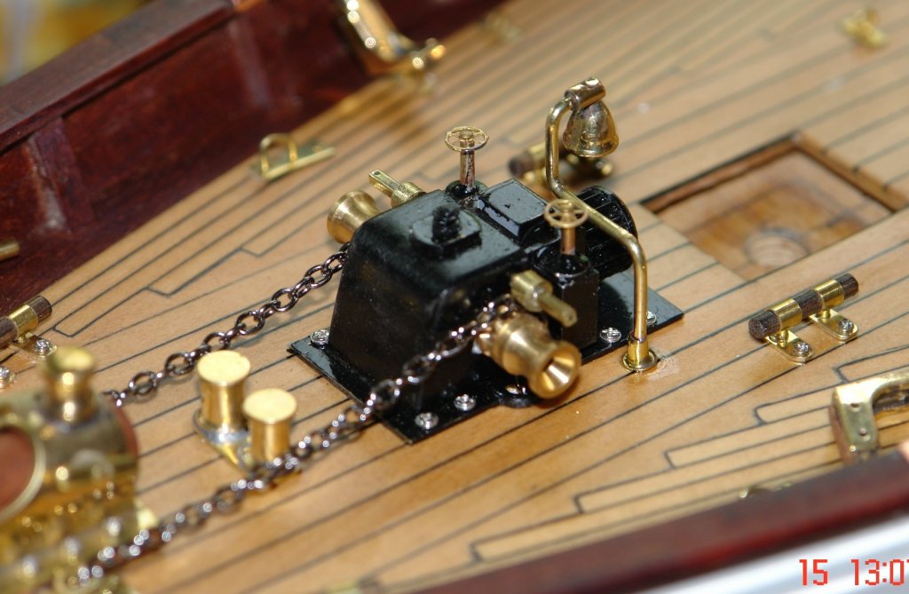
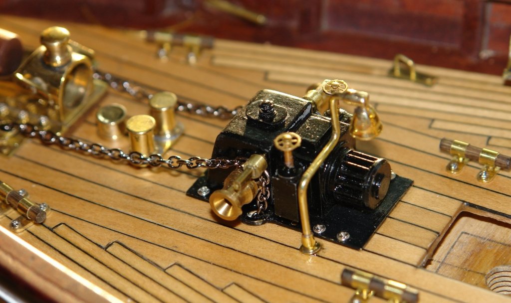
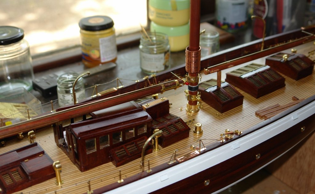
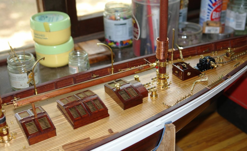
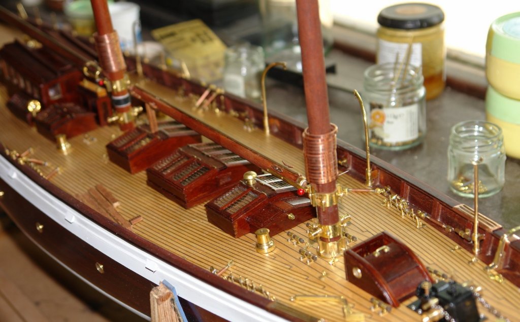
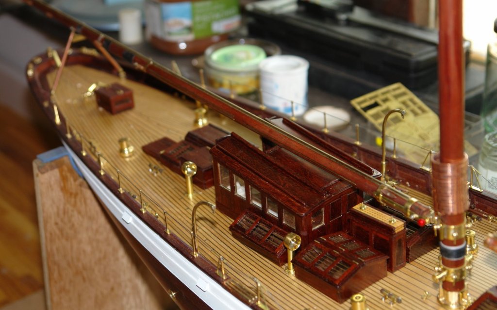
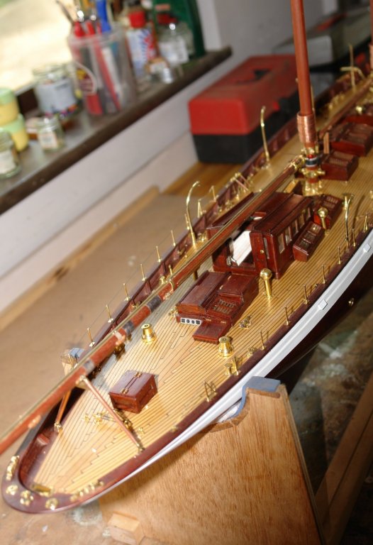
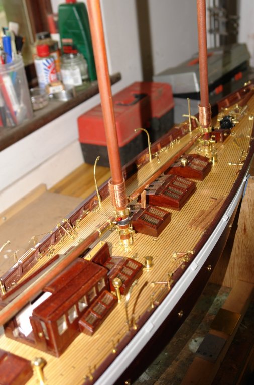
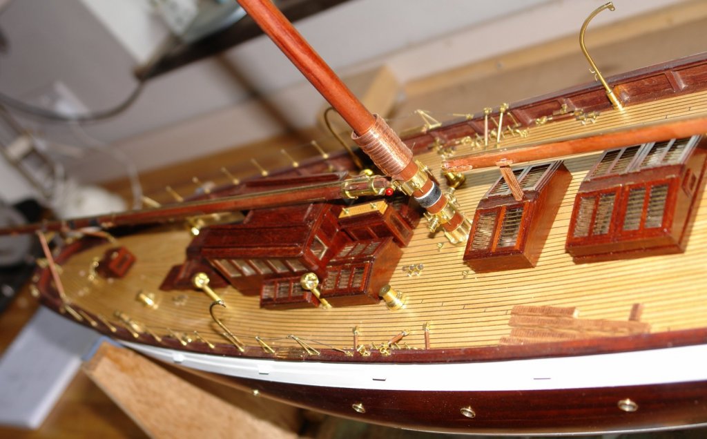
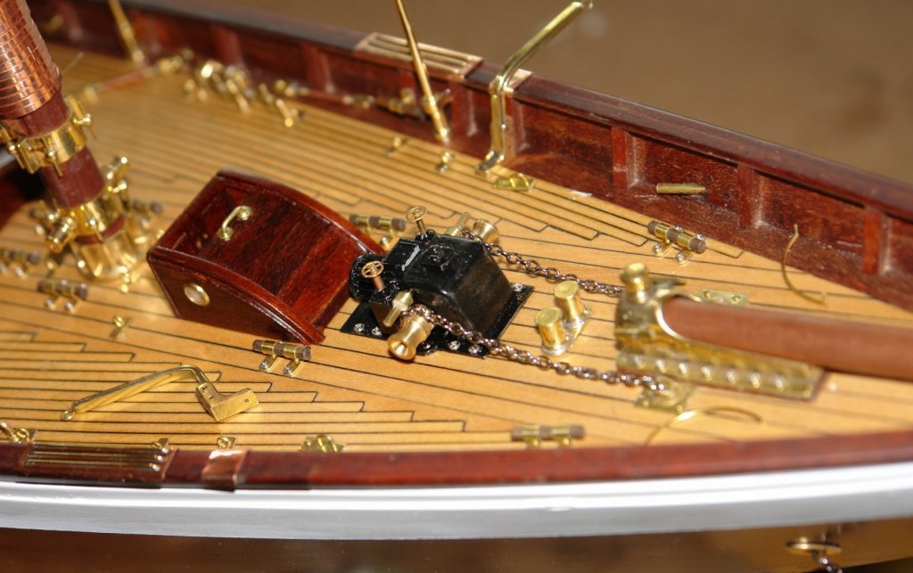
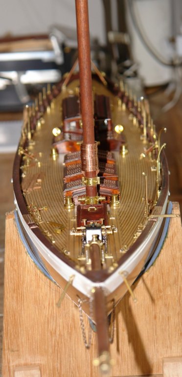
I spent the last few days doing a bit of tiding up on outstanding bits. Also my brother in law was over from Phoenix Arizona and he asked to see progress so far which gave me the opportunity to do an interim assembly. I finished off the cathead - but i will leave fixing until later in the build as they are a bit vulnerable. I also made and attached the rail protection plate that goes under the cathead. I drilled the deck and bolted in position the previously made anchor winch and added the anchor chains. I finished attaching and gluing the yards - and getting them in true alignment ready for gluing the masts in place - hopefully in a couple of weeks time. I then took a series of shots to record the current state of build.


- 882 replies
-
- 11
-
-
Kees, I'm really pleased that your health has improved and you are feeling good about life and work. Long may your improved health last. Job searches can be challenging but my experience is that if you keep at it something good always turns up. Smile a lot, enjoy your family and keep positive.
- 434 replies
-
- 7
-
-
- pelikaan
- beamtrawler
- (and 2 more)
-
Very sad news. Bob was such a friendly soul. He will be sadly missed.
-
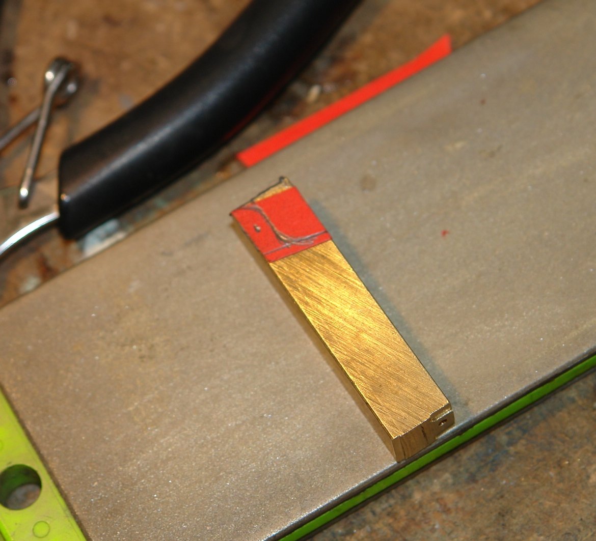
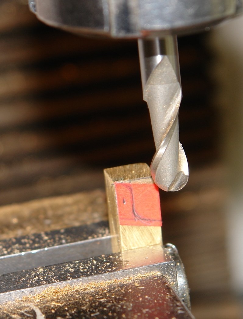
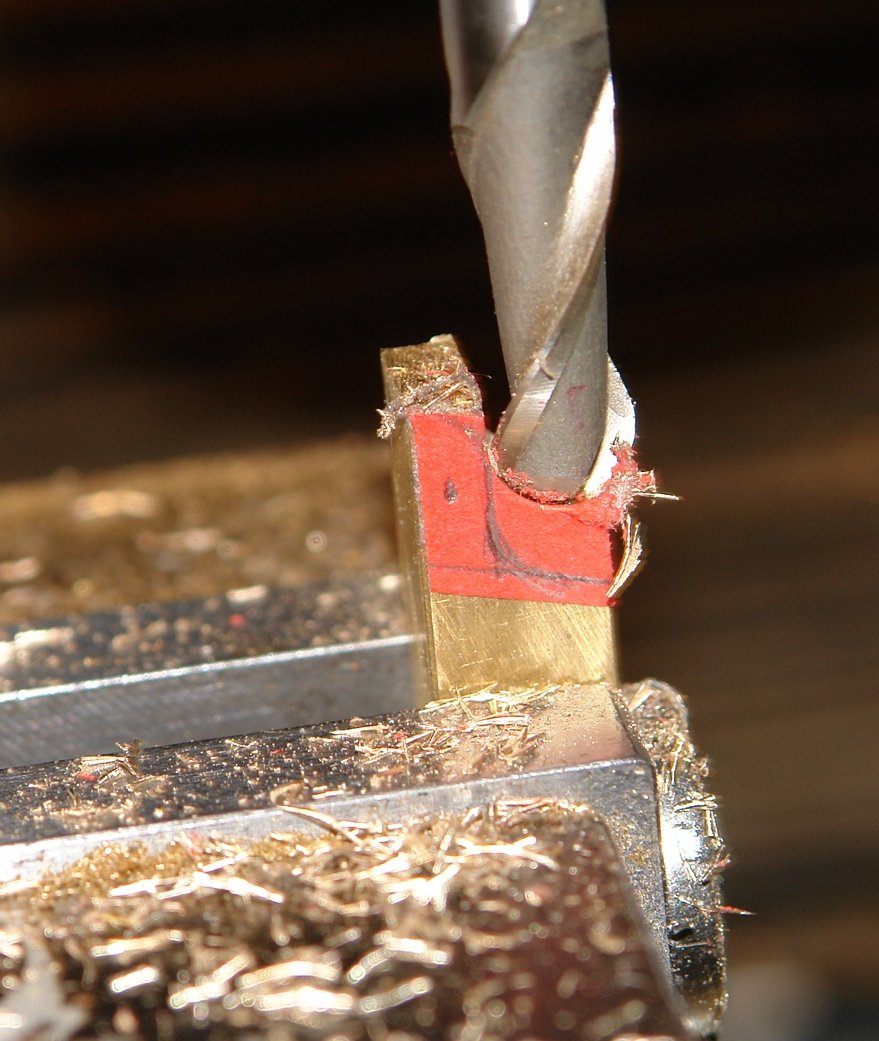
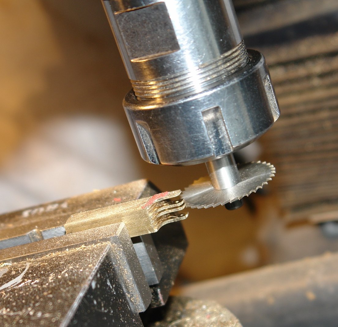
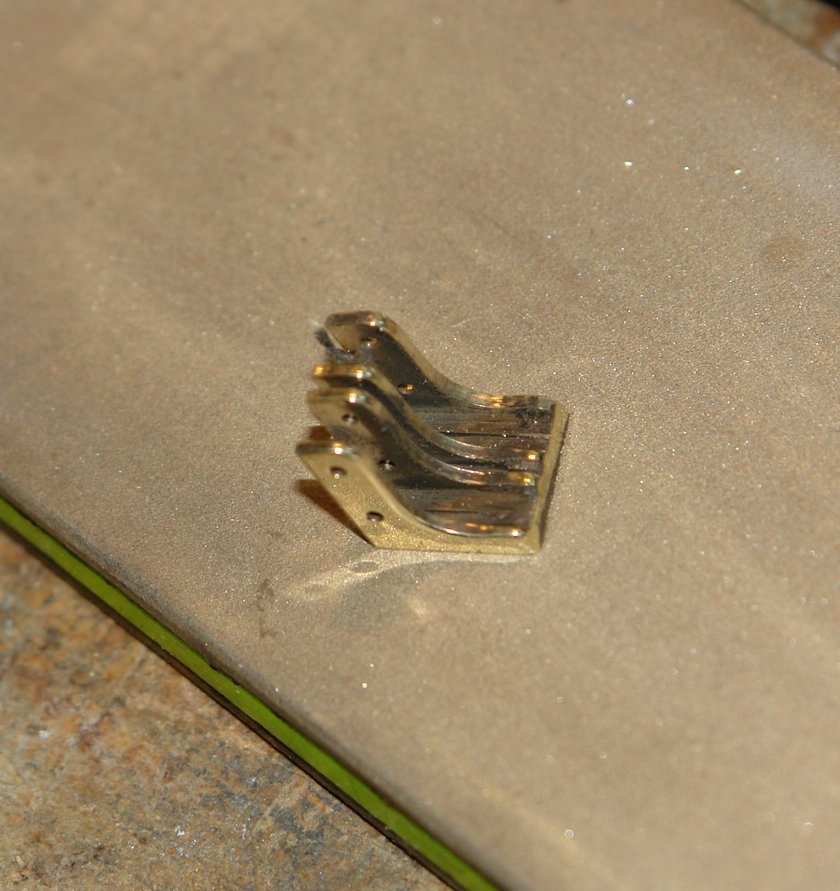
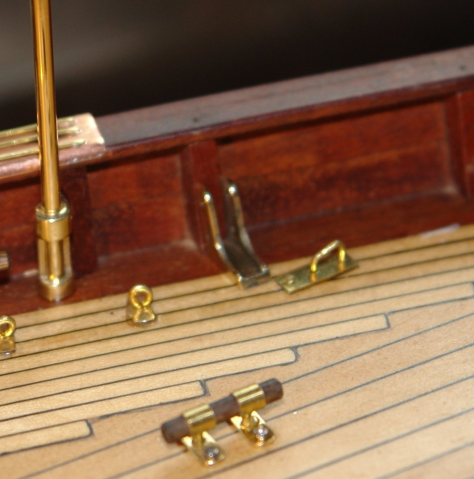
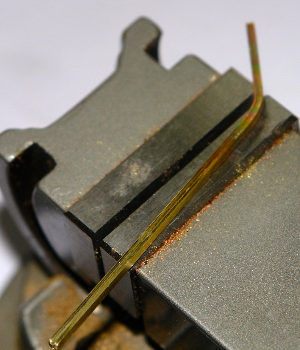
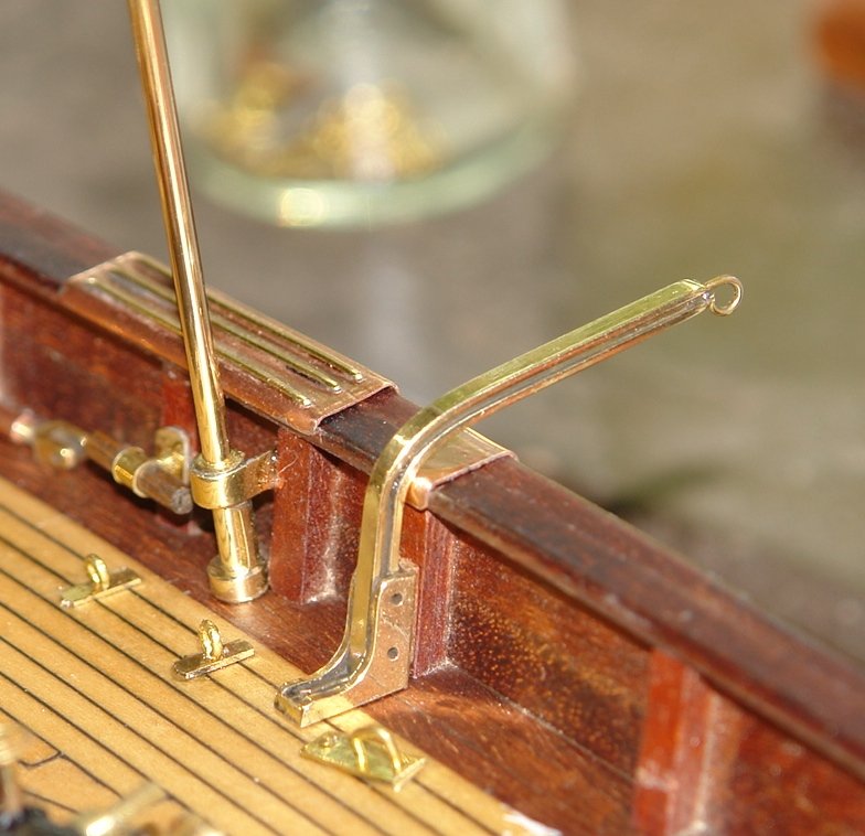
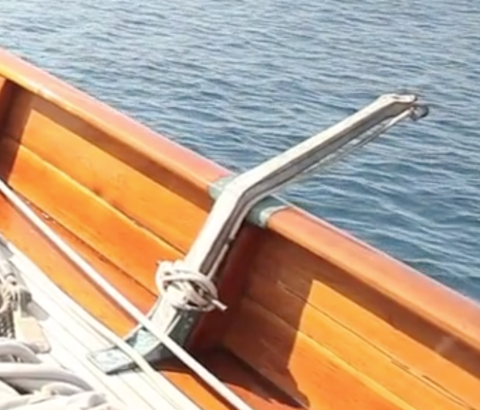
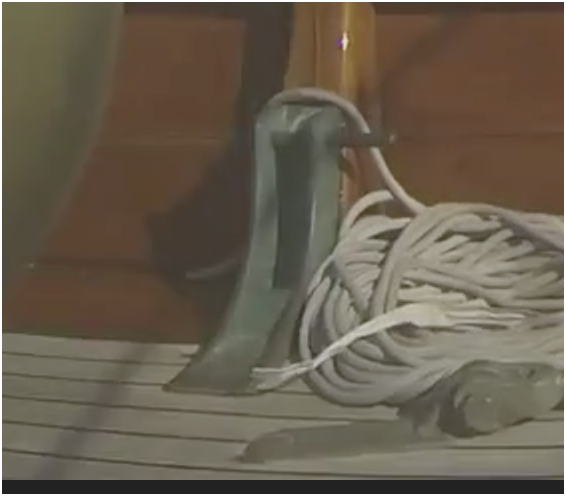
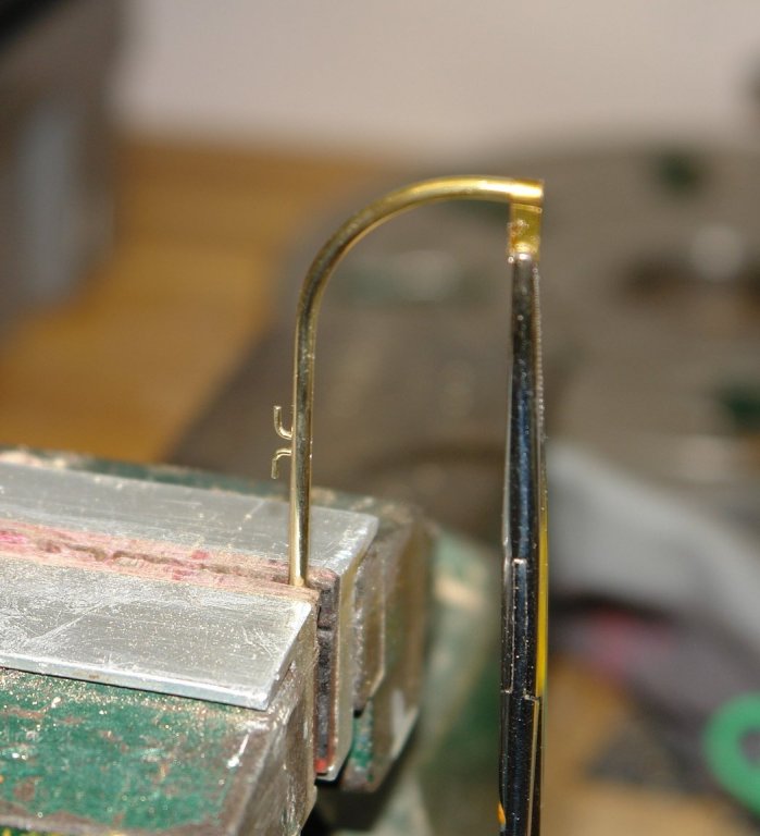
Plodding on:- Today I concentrated on the demountable "cathead" and deck mounting brackets. They are more tricky than they appear, particularly as I wanted them to look somewhat authentic. I scratched my head for a while playing with my box of assorted brass sections but eventually decided I didn't have anything suitable. I resorted to chopping out of solid. The bracket was marked out on a piece of 3/8" bar and the profile was machined on the mill using a suitably sized ball end milling cutter. I made the brackets as a matched pair - slotting out the centre of each bracket using the slitting saw. the pair were finally separated using a jewellers saw. The arm could have been easier but I decided I wanted to reproduce the "I" beam section as seen in the 2nd photo. This involved cutting a .030" wide slot in the arm which had a finished size of .100" x .100". I cut the arm from a .100" thick brass sheet using the slitting saw, the same blade being used to form the "I" section. It was all a bit small and hence difficult to see in the next photo. The 1st slot has been cut ready for turning the sheet round to cut the slot on the other side. The final operation was to part off the beam from the sheet. Bending was a bit tricky as it would have been very easy to collapse the "I" section. Much heating and multiple gentle bends were required. The result however turned out as I wanted. I should finish them tomorrow.


- 882 replies
-
- 10
-
-
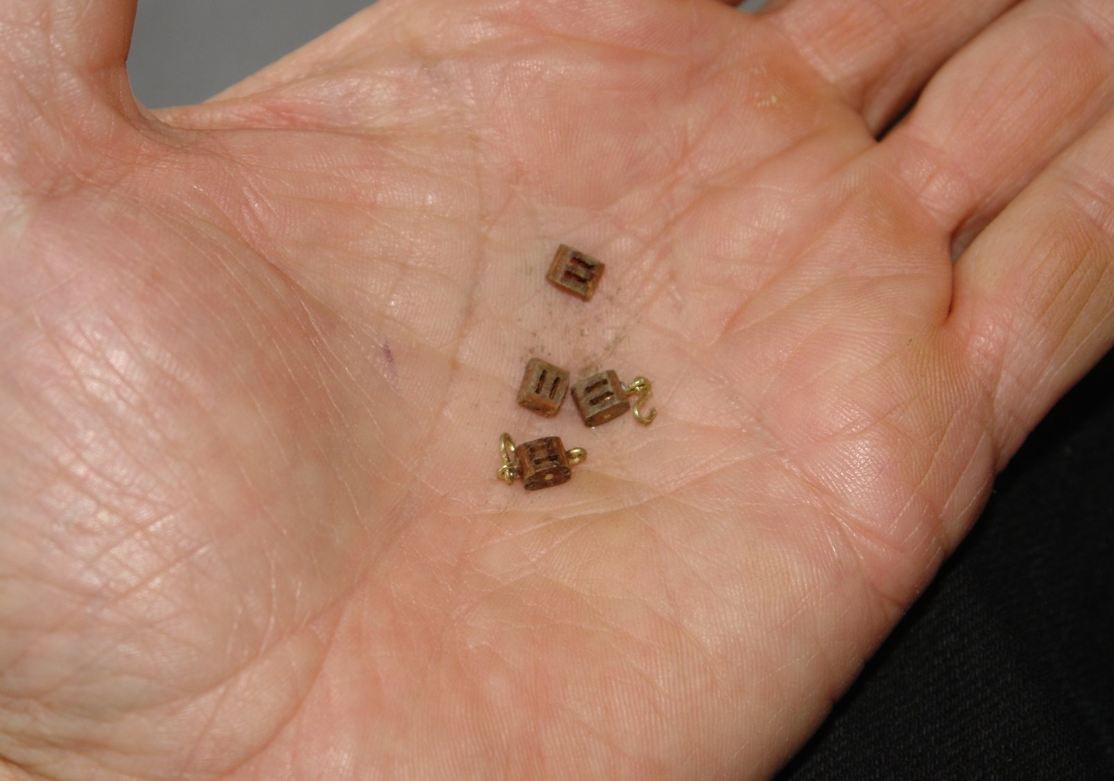
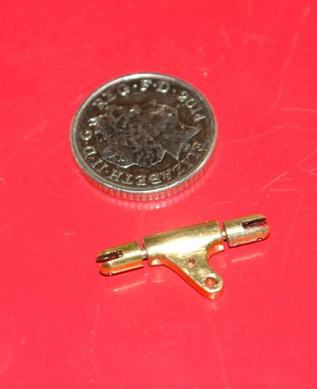
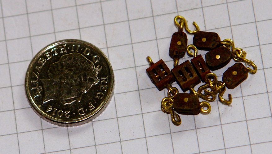
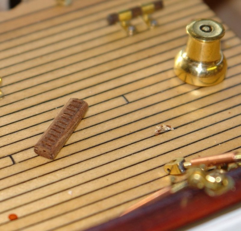
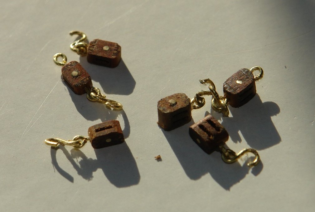
Thank you - my palm is probably not a very good indicator of scale. I have seen many posts which use a Dime as an indicator of scale. I don't have one but its almost exactly the same size as a UK 5 pence so here is a picture of all 8 blocks made yesterday against my "UK Dime". Mark / John thank you for your comments and your continuing visits. Also thank you to all of you who have mastered the new like button. I continue to plod through the remaining deck fittings - not many left now. Today I spent a couple of hours making the staysail boom crutch.

-
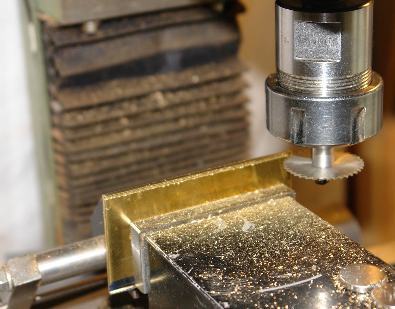
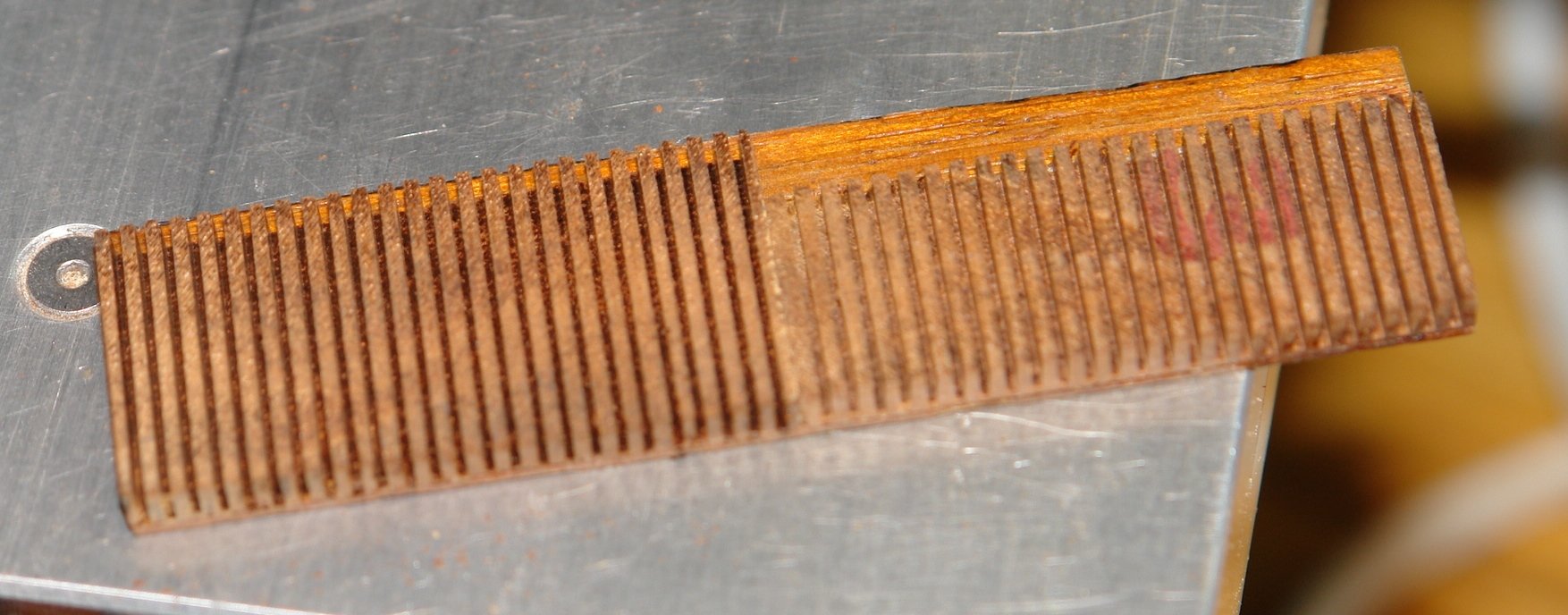
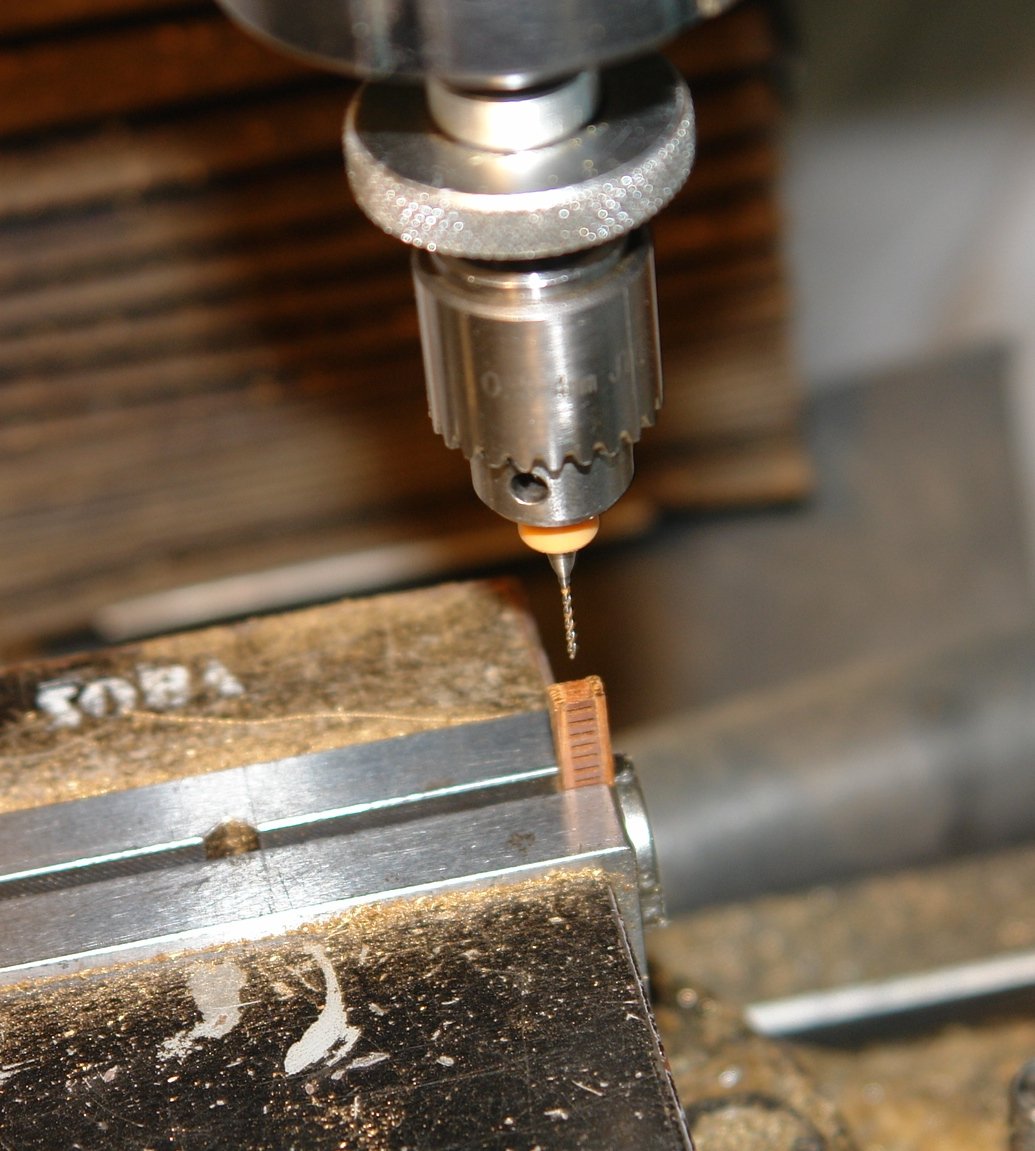
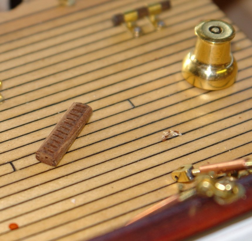
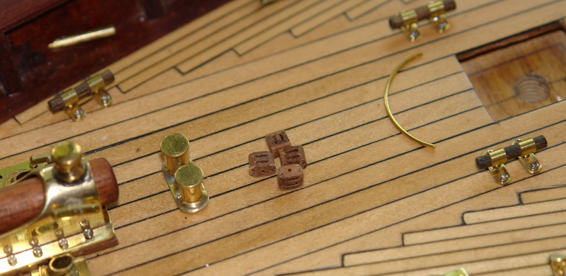
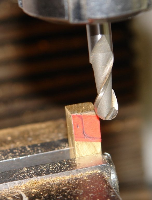
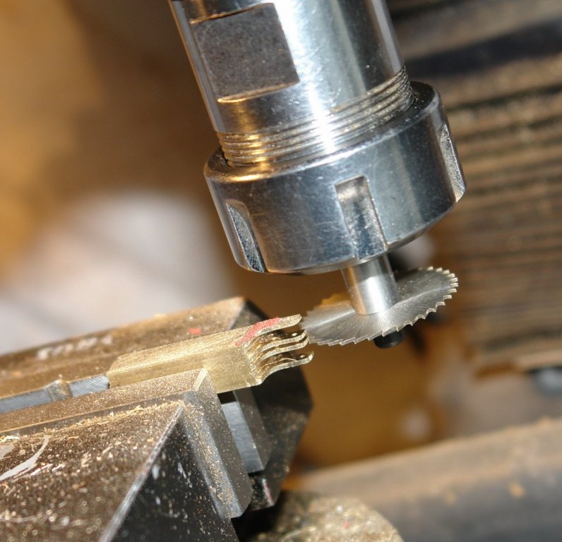
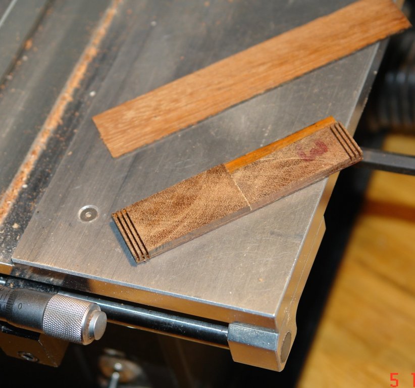
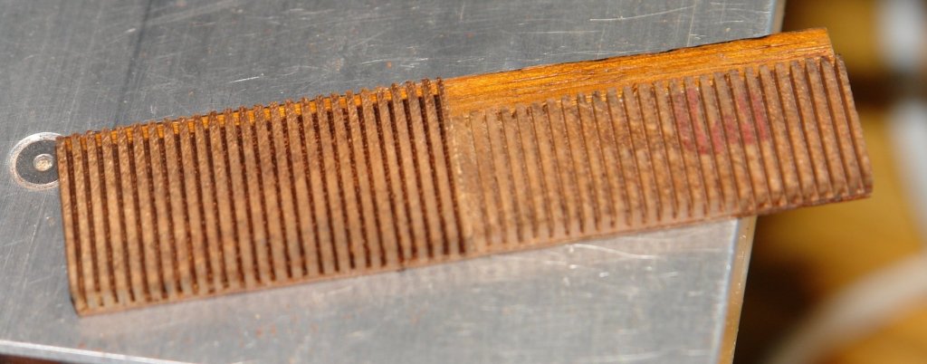
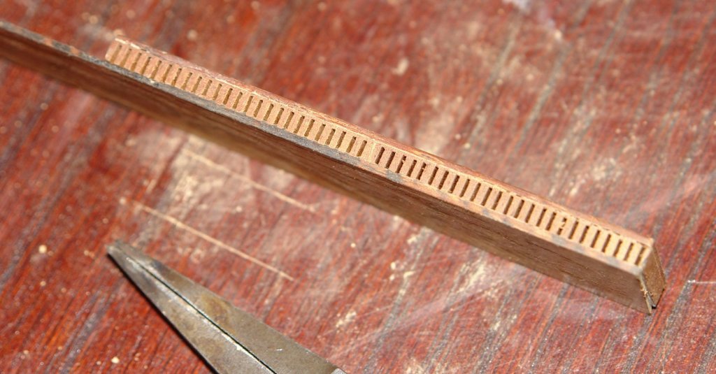
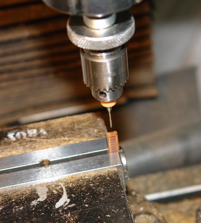
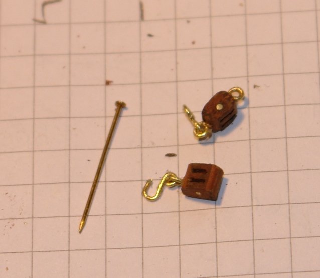
So here goes with another update - predominantly related to making blocks. I sarted however by making 2 further davits for the gangways - the same as the boat davits but slightly smaller. The boat davits each have a pair of double blocks while the gangway davits have singles. 8 blocks in total. I had previously had a go at block making reported in an earlier post. These blocks however are a lot smaller .200" high by .120" wide and required a different technique. I was also minded to consider how the design could accommodate a "production run" approach. I decided on a fabricated approach, made from mahogany and with the wood grain arranged for strength. I cut the top and bottom planks and then glued onto one plank the blocks which would form the webs. The webs were then created using a slitting saw blade - the webs and the gaps between them were 1/32" wide. Once the webs were cut the closing plank was glued in place. The sandwich was then slit down to the finished width of the blocks. I then drill axially along the strips to take the pulley shaft. I also drilled the holes for the eyelet attachments. The strip was then sanded to the oval shape and blocks of the required type were sliced off. The pulley shaft was inserted and various attachment pieces were made from wire.


- 882 replies
-
- 10
-
-
HMS SUSSEX 1693 by 8sillones
KeithAug replied to 8sillones's topic in - Build logs for subjects built 1501 - 1750
Beautifully done - seriously impressive. -
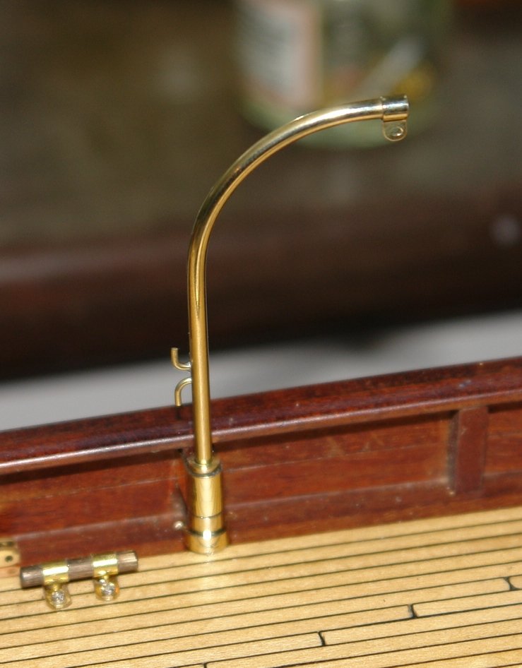
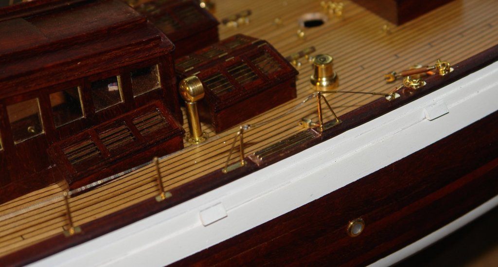
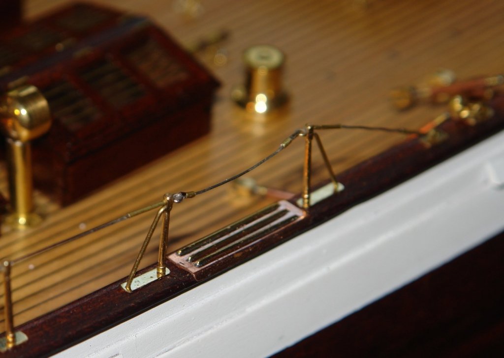
Druxey - Thank you. The wedding is over but the garden needs a lot of work, fortunately today was very wet and so I managed to escape to the workshop to make the boat davits. The davits were made from 3/16" rod. I started by drilling 2 cross holes to attach the cleats (wire). I then made a bending jig so that I could get the curve consistent. I annealed the rod before bending. The end brackets (for attaching the blocks) were made from brass sheet - cut into a strip, folded tightly round the end of the rod and soldered in place. The solder was in the form of paste which made the job less messy. The bracket was held in place for soldering using a medical clamp. The clamp was left to hang vertically under its own weight (which made vertical alignment very easy). The davit mountings were turned on the lathe. I found a bit of profiled tube from which to make the web supports which attach to the bulwark frames. After turning the tube was soldered in place and then the end was cut off with a piercing saw to make make the webs. After polishing the bases were glued in place with 2 part epoxy. the davits were also polished and the job was done. I also found a bit of time to finish the guard rail by making the detachable rail across the step. A very frustrating job given the size of the pieces.

-
John, It's good to to see the start of the wood cutting. What is the relevance of the Museum?
-
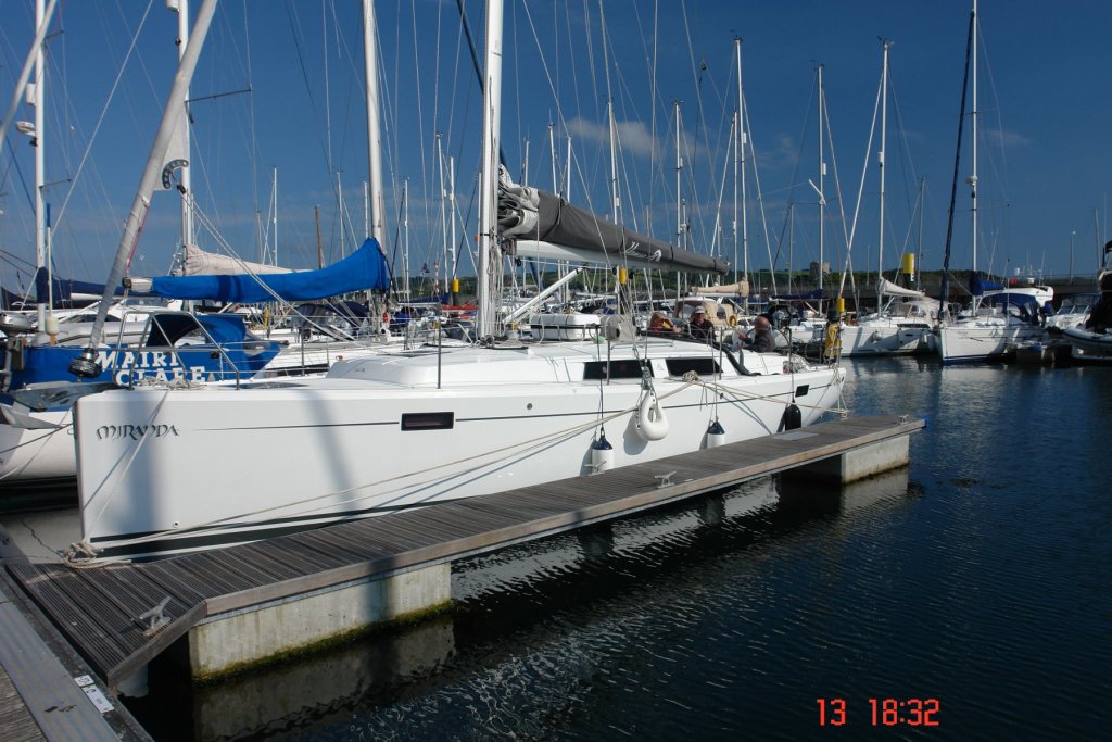
Richard - Hanse 385.
-
Recommendations For A Good Milling Machine
KeithAug replied to Thistle17's topic in Modeling tools and Workshop Equipment
I'm not trying to hide it but seem to be hiding it quite well. Try the link after my name. -
Wow! sanding time, what fun, almost the highlight of the build, only watching paint dry beats it. I hope its hand sanding, doing it by machine is so yesterday.
-
Tecko Very smart. It's times like this when I remember why I chose mechanical engineering as a career.
-
I'm pleased you building again. Hope all turns out well on the health front.
-
Richard, Thank you, Bench grinders are quite cheap and essential if you are going to be grinding HSS lathe tool blanks. May be time to reinvest!!!! Unfortunately as our crew got older we made less and less mistakes. The mistakes are what created the interesting stories. The last trip we were out for 8 days and we broke nothing, not even a cup, glass or plate. In our damage report we were were scraping the barrel with the most significant defect being about 6 inch of stitching which had come adrift on the mainsail bag zip. I have a few historic stories left and may get round to telling them at some time. John, Thank you for your continuing interest. Julie, He was besotted from the moment they met and proposed at the top of the Canyon Overlook trail in Zion NP, one knee, ring and all. Nils, Thank you, The deckhouses are natural antique mahogany, I didn't need to stain them. I can recommend cutting up old furniture.
-
I find myself looking at the crew and passengers and wonder what they are thinking. My guess is the bridge crew are looking out and wondering where the sea went.
- 2,625 replies
-
- 4
-
-
- kaiser wilhelm der grosse
- passenger steamer
- (and 1 more)