CDR_Ret
-
Posts
656 -
Joined
-
Last visited
Content Type
Profiles
Forums
Gallery
Events
Everything posted by CDR_Ret
-

3D Printing Cannons in Resin
CDR_Ret replied to thibaultron's topic in 3D-Printing and Laser-Cutting.
Or you could move to the Dark Side for free and try 3D printing using the Blender extensions.🙂 -
Cold War madness
CDR_Ret replied to Martes's topic in CAD and 3D Modelling/Drafting Plans with Software
Brings back memories as a young USN air intelligence officer doing ship recognition briefings for the carrier pilots 'way back during the Cold War. Kotlins and Kashins involved in "shouldering" incidents in the Med. Krestas shadowing the CBGs. Fun times--not! -
CCClarke, please see my PM. Terry
-
Paviljoensjacht 1733 | Blender
CDR_Ret replied to Robska's topic in CAD and 3D Modelling/Drafting Plans with Software
Robska, You may have already noticed this, but there are some glaring errors between the various views in these plans: At the bow in the halfbreadth view, there appears to be a very wide rail wrapping around the bow of the vessel. But if you look at the profile elevation view, the planking of the bow wraps up and back toward the stern, forming a very cheeky profile. The upper railing is well aft of the forward edge shown in the lower view. The two views simply don't match (unless the railing details were omitted for some reason in the lower view). At the stern, referring to profile elevation, the intersection of the poop deck's side railing and the molding around the stern windows corresponds to the extent of the deck planking in the lower view. So, unless the deck planking is flush with the railing (unlikely), there is a problem with the drawing in this area. What is the provenance of this drawing? How old is it and from what was it taken? Terry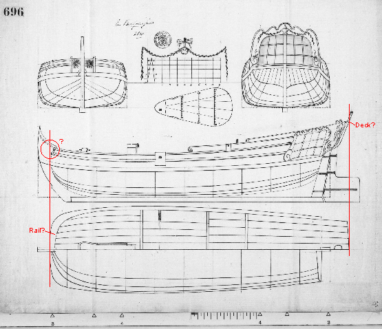
-
Paviljoensjacht 1733 | Blender
CDR_Ret replied to Robska's topic in CAD and 3D Modelling/Drafting Plans with Software
One of the more difficult aspects of getting started in DELFTship for the novice user is inserting the background reference images. May I suggest that you download the tutorial I created several years ago (attached). I haven't updated these files for the current version of DELFTship Free, so the manual references and illustrations showing program controls will not reflect the latest version. You should be able to sort things out, since the background image insertion feature hasn't changed much, if at all. I recommend reading all five parts of the tutorial before starting a model. Please message me if you run into issues getting started. The tutorial is quite wordy, I'm afraid, but it does the job the Manual does not. Just take your time working through it. If you find any mistakes, please let me know so I can correct them. No one has reported any issues in the past two years! This is how a complete hull appears displaying the Gaussian surface ("Gauss") tool. I used my 1891 brigantine Galilee model for this example. Surfaces that are either flat or curve in only one direction (like a cylinder) are green. Surfaces that curve in more than direction shade toward yellow, orange, and red, depending on the rate of curvature. This tool takes some practice to interpret the fairness of the hull shape—and how to make corrections. The image also shows the station, waterline, and buttock "intersections" with the outer hull surface. You can add as many intersections as you like to help define the hull shape. Just remember that you are trying to match the intersection lines to the corresponding lines in the plans, not the control net nodes! The "Zebra" and "Environmental map" surface reflections shown on the tool bar are more helpful in surfaces that are geometrically smooth, like fiberglass (think: racing yacht). The Gaussian tool is fine for wooden hulls. Don't be surprised if you find that the as-drawn plans aren't smooth and fair in this program. The plans reflect their age, drafting methods, and provenance. You will have to decide how great a departure from the plans you will accept to obtain a smooth hull! DELFTship is a mathematical program. Wooden ships are handcrafted. Terry Part 1-DELFTship_Bkgrd_Images.pdf Part 2-DELFTship_Bkgrd_Images.pdf Part 3-DELFTship_Bkgrd_Images.pdf Part 4-DELFTship_Bkgrd_Images.pdf Part 5-DELFTship_Bkgrd_Images.pdf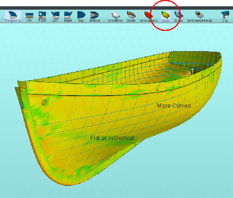
-
Paviljoensjacht 1733 | Blender
CDR_Ret replied to Robska's topic in CAD and 3D Modelling/Drafting Plans with Software
Hi Robska, I am not familiar with 18th century northern European ship plans and drafting conventions, but the first questions that occurred to me after examining the drawing were: Are the station lines drawn at the outside or inside of the hull planks? What are the units used in the dimensions shown on the drawing? Before getting too far into drafting in Blender, you may want to validate the shape of your ship's hull based on the plans you have by using DELFTship Free. Unlike other 3D drafting programs, it is first and foremost a naval architectural program that includes a number of tools for displaying station, buttock, diagonal, and waterlines, and for checking hull fairness. Its learning curve is fairly steep, but nowhere near as steep as Blender's. And when you have a hull you are satisfied with, you can import it into Blender to do the detailed structures and texturing (which are really hard to do in DELFTship). A number of us here on MSW are familiar with DELFTship and can help you if you get stuck. Will be looking forward to your progress on this vessel! Terry -
Hi Tony. Here is my two cents (US), for what it is worth. (In this economy, that's not much!) When using photos for such references, it seems that you would need to know at least the focal length (F/L) of the camera lens before even beginning the process you describe. Also, knowing the distance to object factors into this, which determines the angular relationships between objects in the view. Then there is the matter of how these same factors display in the 3D software. For example, Blender allows the user to set the F/L of the viewport and cameras used for rendering the image. You can also set the camera-to-object distance in the program. On the other hand, the perspective view in DELFTship has a fixed F/L that is not stated in the program. (You may be able to communicate with the D/S staff to find out what the program's effective F/L is.) And you have no idea what the viewing distance is to the object. Then there is Sketchup, which I haven't used in many years, that provides both orthogonal and perspective views, but again, the F/L of the perspective view wasn't given (at least back when I was using it). I have no idea if this information is available in the 3D programs like Rhino, Fusion 360, or others used by members in this forum. Another problem to deal with is the foreshortening of objects in the line of sight. Trying to estimate the breadth of the hull at various points along the rail, for example, using a more-or-less broadside view of the vessel would be extremely problematic, if not impossible. The best you could arrive at would be a very rough guess. I've had more than two decades of experience with this kind of frustration using 120-year-old photos of the brigantine Galilee to reconstruct the ship's plans. I have a treasure trove of more than 60 photos of the ship. But trying to conduct photogrammetry to obtain accurate dimensions of various structures has been extremely difficult, for the reasons stated above. Just trying to determine the list of the ship in broadside views turned out to be mostly a very rough guess. Thankfully, I had a reasonable (but not accurate) set of hull plans to start with, from which I was able to make the dimensional adjustments to conform to the photos. Without some sort of baseline dimensions to work with, what you propose would be fruitless, I'm afraid. Perhaps the photographic experts here on this site may be able to weigh in on this topic. Terry
-
Remains of 500 year-old shipwreck: Dated 2019
CDR_Ret replied to Allegheny's topic in Nautical/Naval History
Wierd. The first time I accessed it I read the article. Now I'm boxed out. The article mentions the survey was conducted by some organization in Stockholm. Can't recall the details. -
Remains of 500 year-old shipwreck: Dated 2019
CDR_Ret replied to Allegheny's topic in Nautical/Naval History
You might try starting from this link: https://www.nytimes.com/2019/07/22/science/shipwreck-archeology-shipwreck.html The Mail story didn't provide any information on the organization that did the survey. Terry -
We rode out Cat 5 Hugo in North Charleston back in '89. No storm surge for us but the wind took off all the pines 40 feet above the ground like a chain saw. No power for nearly three weeks. Praying for you folks down there. Terry
-
Welcome from Colorado Springs!
-
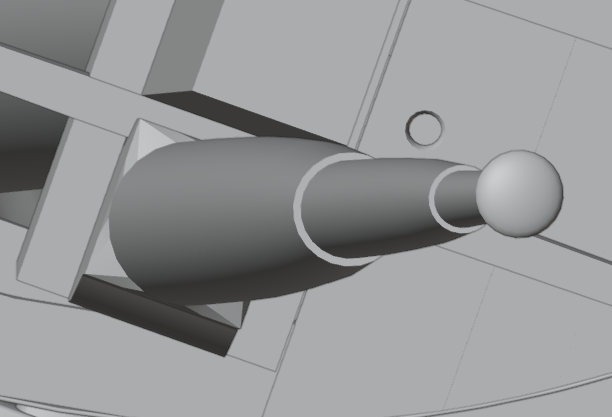
With reference to post #4 of this thread, this highly foreshortend digital view of my model's combined foretopgallant and royal mast shows the mast profiles according to Underhill's tables. A tool working on the principle of a pencil sharpener, if that is what is being described, wouldn't be able to produce the required profile. My two cents. Terry
-
Welcome to MSW Charles. You probably are aware that "Tench" was the name of the lead ship of a late-WWII class of US submarines. The namesake conducted three war patrols from Hawaii. So that struck me as an interesting connection. You will discover that MSW is a wonderful, friendly, and supportive community with an immense knowledge base for this hobby! Terry Colorado Springs, CO
-
3D Longboats in Blender
CDR_Ret replied to 3DShipWright's topic in CAD and 3D Modelling/Drafting Plans with Software
Wow! -
Weird! Almost word for word...
-
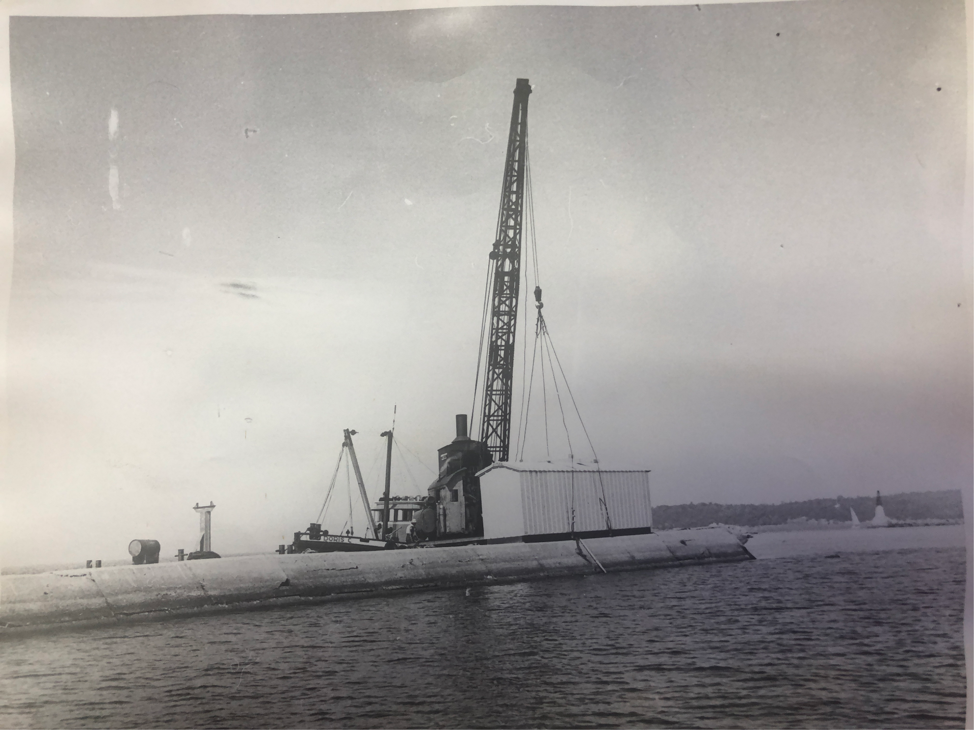
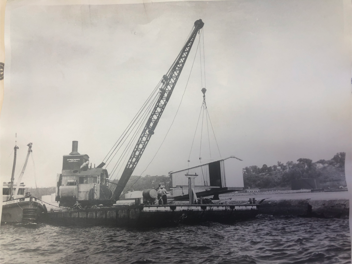
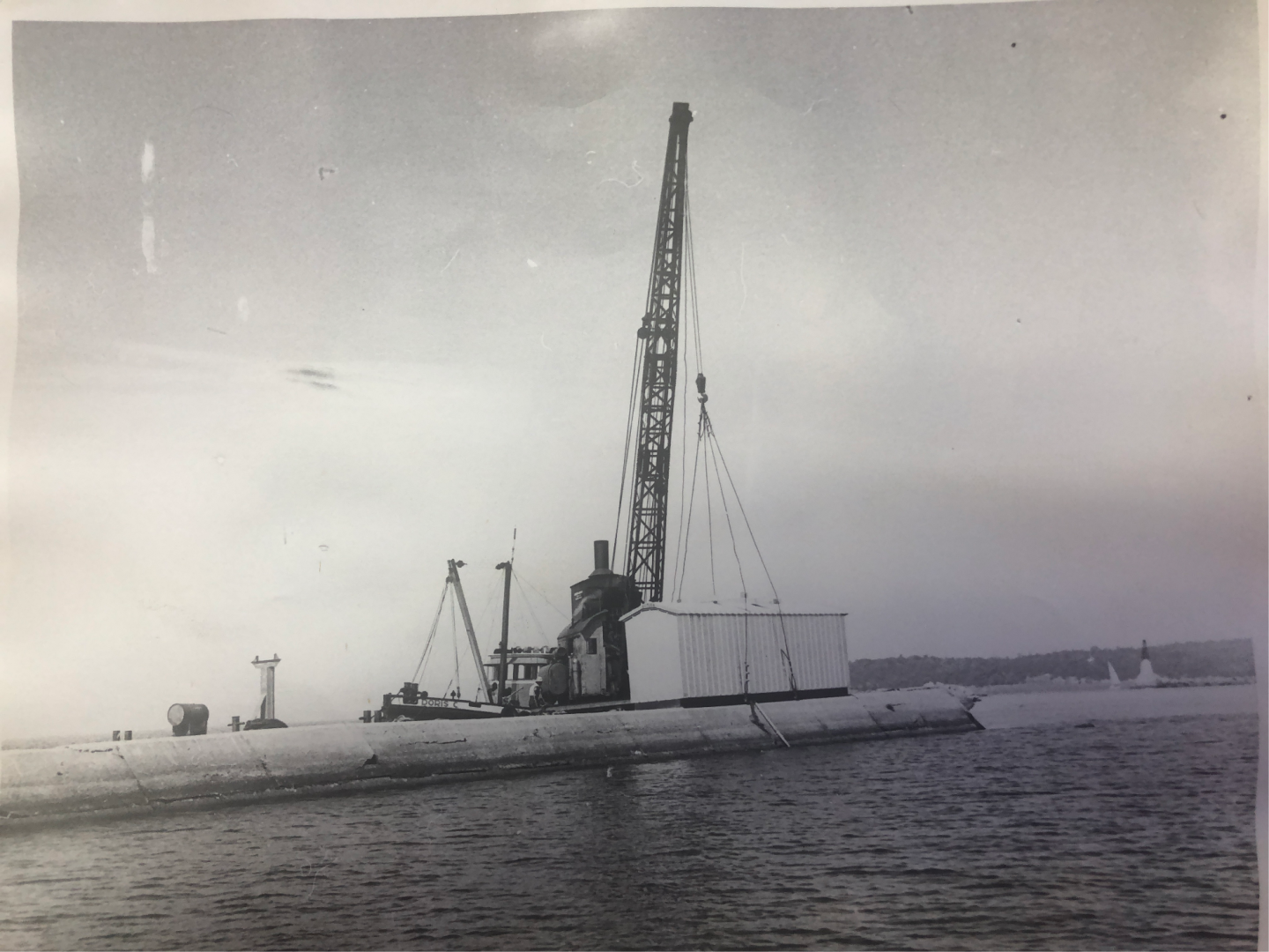
This reminds me of the steam-driven pile driver barge operated by the Lake Champlain Transportation (LCT) Company back in the day. I drove 100-ton-class car ferries for the company between Vermont and New York during my college years. Same thing in principle but different in the details. From what I recall 50 years ago, it was all-steel construction with a steam boiler under a deckhouse within the swivel cab and heavy composite hoses connected to the hammer driver cylinder. The company's work tug was propulsion. You could hear the pile driver working from miles away! The steam-engine crane (not sure you could call it a donkey engine) also pulled damaged pilings out. Very entertaining for the passengers when pulling a ferry into an adjacent slip! [Edit: 7/15/24:] So as to not hijack Keith's topic any further, I'll post my marginally-relevant information here. I contacted LCT, and their Operations Manager was able to locate several photos of the steam crane I had mentioned in this post. Nothing too close up, but they provide an idea of an early-to-mid-1900's barge-mounted steam crane. The company's little work boat is also shown. Terry
-
Free CAD program
CDR_Ret replied to Frank Burroughs's topic in CAD and 3D Modelling/Drafting Plans with Software
What you say is true, @xanthar, but the program uses a whole different approach to generating a surface, which I'm sure you are aware of. (When people talk about NURBS, my eyes glaze over . . .) In order to create an accurate and fair surface, you must introduce "intersections" that correspond to the lines on the plans you are working with. Once the applicable station, waterline, buttock, and diagonal coordinates are entered into the Intersections tool, and Intersections are enabled for the hull layer you are working with, simply moving the control points until the intersection lines align to the applicable lines on the plans creates the desired hull surface (and there are some basic rules for doing this). DELFTship control points almost never lie on the actual surface you are forming. The greater the curvature of the surface, the more intersection lines (and control points) you will need. This may require displaying more station, water, or buttock lines than the reference plans may contain, which is where fairing tools come in. DELFTship has a whole bunch of fairing tools (i.e., basic shading, developable surfaces, Gaussian surfaces, zebra stripes, and environmental reflections) that involve various visual cues, including highlights, colors, and reflection patterns, to create a smooth, fair surface. After iteratively adjusting the hull surface to a visually or Gaussian fair form, you will likely find that the principle intersection lines don't exactly agree with the reference plan lines, as noted earlier in this thread. This is mainly due to the fact that taking off lines and converting them to 2D lines plans was as much an art as a science. The fidelity of the process depends on many factors, including the skill of the yard workers and draftsmen, the age of the original plans themselves (older physical drawings tend to shrink and warp with time), and physical factors pertaining to the hull, such as hogging, or perhaps the original hull wasn't perfectly fair in the first place. (My project's hull had a five-inch hog over 135 feet—which I ignored!) Another feature that affects the fairness of a DELFTship model surface is the "Precision" setting. The higher the precision, the more sensitive the fairing tools are to adjustments, and the more fair the surface will be. I haven't tested this, but I believe the higher the precision setting, the finer the exported STL mesh will be as well (in the Free version). Once you have an accurate, fair hull, you can export the file to another 3D program of your choice, confident that the basic hull form will provide a valid base for the rest of the model. I wouldn't bother using DELFTship for smaller details, though you can create them in DELFTship (I did). It's not designed for that—it's primarily a naval architectural program to evaluate the form and physics of modern vessel hulls and superstructures. For this reason, a lot of modeling features one would expect to be included in a 3D CAD program are either absent or work in such a klugey manner that they can drive you to distraction. PM me if you want to learn how to work around some of these so-called DELFTship "features." Terry -
I usually type in the text for a post in its entirety and leave a space (Return) between paragraphs. Then I upload the images I want to include in the post. This is a separate and preliminary action to actually inserting the image. Their thumbnails appear in a row in the UPLOADED IMAGES section below the text window. Next, you place the cursor at the location to insert the image within the text (usually at one of the blank lines). And finally, hover your cursor over the image you want to insert, then click on the "Insert" button that appears. That action inserts the image into the post. The default alignment is left-aligned. You can center the image by ensuring your cursor is adjacent to the image and then left-clicking the center alignment icon in the formatting row at the top of the post. You can also resize the image after it is inserted by double-clicking it. You can only make it smaller than its original size. And make sure the "Keep original aspect ratio" checkbox is checked, otherwise your image will be distorted if you change the width. Terry
-
Free CAD program
CDR_Ret replied to Frank Burroughs's topic in CAD and 3D Modelling/Drafting Plans with Software
Hello Frank. After working with various 3D CAD programs for nearly two decades, I think that you should first decide what the ultimate purpose and scope of using this approach will be for your projects. Are you primarily intending to reconstruct and fair existing plans? Is your intent to 3D print the entire hull structure and superstructure? Or are you mainly interested in printing the smaller parts and otherwise creating the ship's structure out of conventional materials? For validating and fairing existing ship's plans, especially those from the 19th century and earlier, I recommend the DELFTship Free software. It is a for-the-purpose naval architectural program that defaults to three standard views, provides infinitely customizable stations, waterlines, buttocks, and diagonals, and has reasonably easy-to-use modeling tools such as Gaussian and developable visualization of hull surfaces. All these features are built-in and appropriate for ship design and modeling. This is the go-to program for developing smooth, fair hull surfaces. The poor documentation for the hobbyist and nautical research modeler is its main drawback, in my opinion. Search this forum using the term "DELFTship" to take a look at some of the results by several modelers/researchers (myself included) using this program. For 3D printing large components such as the hull, deck cabins, boats, etc., you may want to check out some of the software mentioned above. I have no experience with that application. For small details and relative ease of modeling, I would go with the free, open-source, full-feature Blender program. However this program has a notoriously steep learning curve. Take a look at the Blender tutorial series by BornCG on YouTube if you want to consider this route. The instructor is an excellent teacher who doesn't assume you know what the buttons do and how the multitude of program features work. Sadly, most of the competent 3D programs do have that steep learning curve, so plan on spending some time figuring out ship design within the program you choose. Some of the standard 3D CAD programs are pretty clunky when attempting to create a continuously varying surface in 3-space that must conform to an existing set of plans. I can assist with DELFTship. @3DShipWright and @Martes may provide assistance with Blender. Take a look at their models, which are both accurate and very aesthetic. They are going more for illustrative results than 3D printing. Terry -
Hello Doug from Colorado Springs! Welcome aboard. Terry
-
Ship Ribbing with CAD?
CDR_Ret replied to Sanjith_D's topic in CAD and 3D Modelling/Drafting Plans with Software
I would recommend checking out this thread regarding laser-cut frames, etc. Kiyoo Iizawa was actively involved in this forum a few years ago and did some beautiful work using CG modeling and laser-cut components. He was writing a manual/book to help modelers get into laser-cutting modeling, but after some attempts at collaboration, I think there was an (amicable) divergence of views on how to present the process. Terry -
Ship Ribbing with CAD?
CDR_Ret replied to Sanjith_D's topic in CAD and 3D Modelling/Drafting Plans with Software
IMHO, going directly from existing drawings to code that drives a 2D laser cutter is risky when cutting out frames or bulkheads. I have no experience with the quality of plans from the big national museums and other credible sources, but when I manually compared the body and halfbreadth plans of my 1891 brigantine project, it was an exercise in frustration. Heights and breadths of station and waterline intersections did not agree among the three views. The point I am trying to make is that there is no guarantee that using existing plans (especially if they are old, original drafts) will drive a laser cutter that will result in a smooth, fair, hull surface without a lot of extra work. The above observation was the reason I went to CG drafting in the first place. After nearly a decade of periodic frustration, trying different methods and different copies of plans from the Smithsonian and other museum/library archives, I found that using the DELFTship Free naval architecture software was pretty much ideal for fairing out the hull lines because it had the features needed to visualize the shape of the hull, remove low and high spots, and compare the resulting lines to the original drawings. The bottom line here is that obtaining a set of working plans that will actually be fair and eyepleasing in the real world won't necessarily yield the same set of station lines, waterlines, and buttock lines as in the original set of plans you obtained. It is up to you how far you are willing to deviate from the original drawings. There are a number of MSW members who have posted their projects using DELFTship Free, including my own. Comparison of the final modeled stations (green) in DELFTship Free compared to the original G.C. Berger drawing stations. Waterlines (blue) were included to ensure the correct vertical scale. To understand the genesis of these lines, please refer to the Galilee research log in my signature. (High-resolution plans obtained from the San Francisco Maritime National Historical Park Library; G.C. Berger, Pacific Marine Research Society; Date and provenance unknown.) Once you have what appears to be a valid set of lines to work with, then you can start thinking about what laser setup to use for cutting out your parts. Remember to cut to the outside-most of the front and back curves for each frame or bulkhead. Terry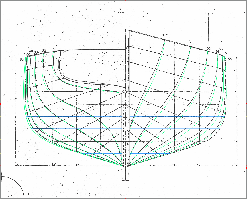
-
USF Confederacy in 3D | Blender
CDR_Ret replied to 3DShipWright's topic in CAD and 3D Modelling/Drafting Plans with Software
Beautiful, Nate! Terry -
3D Ropes/Rigging in Blender
CDR_Ret replied to 3DShipWright's topic in CAD and 3D Modelling/Drafting Plans with Software
So far, so good! -
Welcome aboard, Kevin! Yeah, the Lewis and Clark is nothing but HY-80 razor blades. There are quite a few (mostly former) bubbleheads as members here. Terry