
MORE HANDBOOKS ARE ON THEIR WAY! We will let you know when they get here.
×


Cathead
-
Posts
3,433 -
Joined
-
Last visited
Reputation Activity
-

 Cathead got a reaction from popeye the sailor in Arabia 1856 by Cathead - FINISHED - Scale 1:64 - sidewheel riverboat from the Missouri River, USA
I'm now working on the cylinder timbers, the pair of large timber frameworks that support the piston engine and paddle wheel on each side of the boat. A full original set is on display at the museum. although the tight quarters and large size made it very difficult to photograph the entire assembly in one view:
Thus, for reference, here's the drawing I made of these based on measurements and photos taken at the museum. I've printed these out at scale and used them as a template for the model:
Each set of cylinder timbers consists of a larger assembly that extends to support the wheel, and a smaller assembly that supports the other side of the piston engine but is much shorter. Here's a view from the engine end, looking toward the stern. The (port) wheel is on the view's right, so the assembly to the right is the big one, while the one to the left is the smaller one that only supports the engine. I hope that's clear.
And here's what I've built so far. I started by carefully cutting the thickest angled piece under the engine and using that to define where each of the larger beams went. From there, I'm slowly filling in the shorter support blocks. I'm building both sets of timber assemblies at the same time to ensure that they match, even though it really doesn't matter since they don't connect across the boat in any way. I just think it's helping me make them correctly to do it together (and reduces the redundant feel of starting over on the second one after finishing the first). Current status of one set (the other looks the same) next to a template:
I've now run into an interesting problem that I hadn't noticed before. Both the large and small sides have wooden braces at the stern end that angle down from the thick cylinder timber to act as a counter-brace (these are on the right side of the drawings posted above). On the large assembly, they simply butt up against the timber end with a metal bracket connecting the two, and what looks like a simple mortise on the lower one:
But on the short assembly, there's a strange quirk about the connection between the timber and the brace:
In the image above, notice how the brace (on the left) meets the timber (right) well below the latter's top surface. Moreover, the large vertical bolt that ties all this together is too long by maybe 4-6", what looks like about the same gap (outlined in red). And from above, you can see that there's a notch in the timber. So was there some kind of extra wooden brace that extended from a notch in the timber, over the top of the brace, different from how the other two worked?
I don't know if that explanation and question is clear; I'm sure I suffer from the curse of knowledge from studying this so much. But if that makes sense, does anyone have any ideas? I can't see any evidence for how such a brace would have been shaped if it had existed, and am somewhat reluctant to add something that isn't there in the recovered assembly. But it seems strange to me and I'm just curious about thoughts on this very esoteric question.
Working on these has been a nice change from planking; I'm glad I tackled this next. Thanks for reading.
-
 Cathead got a reaction from thibaultron in How Realistic Can One Make Sails?
I have used heavier bond paper for sails with good results in my opinion. I use artists' pastels to color my paper sails.
-
 Cathead got a reaction from mtaylor in How Realistic Can One Make Sails?
I have used heavier bond paper for sails with good results in my opinion. I use artists' pastels to color my paper sails.
-
 Cathead got a reaction from druxey in Arabia 1856 by Cathead - FINISHED - Scale 1:64 - sidewheel riverboat from the Missouri River, USA
I'm now working on the cylinder timbers, the pair of large timber frameworks that support the piston engine and paddle wheel on each side of the boat. A full original set is on display at the museum. although the tight quarters and large size made it very difficult to photograph the entire assembly in one view:
Thus, for reference, here's the drawing I made of these based on measurements and photos taken at the museum. I've printed these out at scale and used them as a template for the model:
Each set of cylinder timbers consists of a larger assembly that extends to support the wheel, and a smaller assembly that supports the other side of the piston engine but is much shorter. Here's a view from the engine end, looking toward the stern. The (port) wheel is on the view's right, so the assembly to the right is the big one, while the one to the left is the smaller one that only supports the engine. I hope that's clear.
And here's what I've built so far. I started by carefully cutting the thickest angled piece under the engine and using that to define where each of the larger beams went. From there, I'm slowly filling in the shorter support blocks. I'm building both sets of timber assemblies at the same time to ensure that they match, even though it really doesn't matter since they don't connect across the boat in any way. I just think it's helping me make them correctly to do it together (and reduces the redundant feel of starting over on the second one after finishing the first). Current status of one set (the other looks the same) next to a template:
I've now run into an interesting problem that I hadn't noticed before. Both the large and small sides have wooden braces at the stern end that angle down from the thick cylinder timber to act as a counter-brace (these are on the right side of the drawings posted above). On the large assembly, they simply butt up against the timber end with a metal bracket connecting the two, and what looks like a simple mortise on the lower one:
But on the short assembly, there's a strange quirk about the connection between the timber and the brace:
In the image above, notice how the brace (on the left) meets the timber (right) well below the latter's top surface. Moreover, the large vertical bolt that ties all this together is too long by maybe 4-6", what looks like about the same gap (outlined in red). And from above, you can see that there's a notch in the timber. So was there some kind of extra wooden brace that extended from a notch in the timber, over the top of the brace, different from how the other two worked?
I don't know if that explanation and question is clear; I'm sure I suffer from the curse of knowledge from studying this so much. But if that makes sense, does anyone have any ideas? I can't see any evidence for how such a brace would have been shaped if it had existed, and am somewhat reluctant to add something that isn't there in the recovered assembly. But it seems strange to me and I'm just curious about thoughts on this very esoteric question.
Working on these has been a nice change from planking; I'm glad I tackled this next. Thanks for reading.
-
 Cathead reacted to mtaylor in Licorne 1755 by mtaylor - 3/16" scale - French Frigate - from Hahn plans - Version 2.0 - TERMINATED
Thanks for looking in, my friends.
I'm still having eyeball problems (new glasses the cause?). And working on redoing the pumps. The more I looked at them, the less I liked what I saw.
Dan, I'm using the 3rd hand (modified) also. The one's in the pic were from "fiddling"...playing a bit and thinking things through. There's not enough "space" for serving but I'm looking over your method and will try that when I get to the "real" rigging. Re-do that... there's enough room for maybe two or three wraps of seizing but I'll have to check spacing.
Ken, Popeye, and Sam... Yeah.. breaks. I think you're right that I need more of them.
Jaager, the line I'll be using is some 100% cotton (Coats & Clark). No fuzz nd a visible "twist".
-
Cathead reacted to Chuck in Pegasus 1776 by Chuck - 1:48 - Swan-class sloop cross-section
I have been swamped with trying to rebuild my inventory before the Connecticut show. But yes I have made some progress but nothing really new. I basically have caught up to where I was on the earlier version. This is where I am at right now. The good news is that I have completed the set up in shop for some serious model building after the show. I am ready to go and have set up an area to take better pictures.....hopefully. Right now everything is kind of thrown onto the same table....as you can see.
-
 Cathead got a reaction from mmdd in Arabia 1856 by Cathead - FINISHED - Scale 1:64 - sidewheel riverboat from the Missouri River, USA
I'm now working on the cylinder timbers, the pair of large timber frameworks that support the piston engine and paddle wheel on each side of the boat. A full original set is on display at the museum. although the tight quarters and large size made it very difficult to photograph the entire assembly in one view:
Thus, for reference, here's the drawing I made of these based on measurements and photos taken at the museum. I've printed these out at scale and used them as a template for the model:
Each set of cylinder timbers consists of a larger assembly that extends to support the wheel, and a smaller assembly that supports the other side of the piston engine but is much shorter. Here's a view from the engine end, looking toward the stern. The (port) wheel is on the view's right, so the assembly to the right is the big one, while the one to the left is the smaller one that only supports the engine. I hope that's clear.
And here's what I've built so far. I started by carefully cutting the thickest angled piece under the engine and using that to define where each of the larger beams went. From there, I'm slowly filling in the shorter support blocks. I'm building both sets of timber assemblies at the same time to ensure that they match, even though it really doesn't matter since they don't connect across the boat in any way. I just think it's helping me make them correctly to do it together (and reduces the redundant feel of starting over on the second one after finishing the first). Current status of one set (the other looks the same) next to a template:
I've now run into an interesting problem that I hadn't noticed before. Both the large and small sides have wooden braces at the stern end that angle down from the thick cylinder timber to act as a counter-brace (these are on the right side of the drawings posted above). On the large assembly, they simply butt up against the timber end with a metal bracket connecting the two, and what looks like a simple mortise on the lower one:
But on the short assembly, there's a strange quirk about the connection between the timber and the brace:
In the image above, notice how the brace (on the left) meets the timber (right) well below the latter's top surface. Moreover, the large vertical bolt that ties all this together is too long by maybe 4-6", what looks like about the same gap (outlined in red). And from above, you can see that there's a notch in the timber. So was there some kind of extra wooden brace that extended from a notch in the timber, over the top of the brace, different from how the other two worked?
I don't know if that explanation and question is clear; I'm sure I suffer from the curse of knowledge from studying this so much. But if that makes sense, does anyone have any ideas? I can't see any evidence for how such a brace would have been shaped if it had existed, and am somewhat reluctant to add something that isn't there in the recovered assembly. But it seems strange to me and I'm just curious about thoughts on this very esoteric question.
Working on these has been a nice change from planking; I'm glad I tackled this next. Thanks for reading.
-
Cathead reacted to cog in Bismarck by Semorebutts - FINISHED - Trumpeter - 1/200 scale - PLASTIC - with MK1 detail set
Or in Dutch "Kiekeboes" or "Gluurluikjes"
-
 Cathead got a reaction from Canute in Bismarck by Semorebutts - FINISHED - Trumpeter - 1/200 scale - PLASTIC - with MK1 detail set
Or the German equivalent, wieauchimmeresheißt.
-
Cathead got a reaction from popeye the sailor in Bismarck by Semorebutts - FINISHED - Trumpeter - 1/200 scale - PLASTIC - with MK1 detail set
Or the German equivalent, wieauchimmeresheißt.
-
Cathead got a reaction from mtaylor in Bismarck by Semorebutts - FINISHED - Trumpeter - 1/200 scale - PLASTIC - with MK1 detail set
Or the German equivalent, wieauchimmeresheißt.
-
 Cathead got a reaction from lmagna in Bismarck by Semorebutts - FINISHED - Trumpeter - 1/200 scale - PLASTIC - with MK1 detail set
Or the German equivalent, wieauchimmeresheißt.
-
Cathead reacted to popeye the sailor in The Tumblin' Dice by popeye the sailor - Artesania Latina - 1:80 - Mississippi riverboat
OK........I had put them in my oops bag. I needed to split one apart, but I didn't have to do anything about that.........one already did. they need to go in opposite directions. taking the intact one, I did some fitting to see what I can do to get them right. Hugh was correct in his assumption, that the stairs fall short of their goal. they need one more step. I drew the part needed on two different thicknesses of wood, to be cemented together to equal the thickness of the kit steps.
it's a beginning
-
Cathead reacted to popeye the sailor in The Tumblin' Dice by popeye the sailor - Artesania Latina - 1:80 - Mississippi riverboat
I've been meaning to get these pictures up here. I tried a couple of different ideas on the stair issue. I continued with the original idea, adding the stairs to the landing. I then thought that the landing might be a bit too deep.
...if anyone needs a guillotine....or a hangman's platform.......I'm your man I then tried idea #2........the same basic double flight of stairs, but I went higher...and gave it closed in sides.
you see the edge that has been cut out.......I will do the entire flight.
here I get the notion that I've gone too high. perhaps a couple steps lower.
...here are the infamous before and after pictures............
I then did them in mahogany stain......they came out looking blotchy. my next idea should raise my expectations...hopefully take it to the next level.
-
Cathead reacted to glennreader in L’Etoile by glennreader - FINISHED - Billing Boats - Scale 1:50 - Updated to represent her current fitting out
Juhu, thanks for the comment. As you say I much prefer the natural wood and use paint only when It is essential or I think for whatever reason it will enhance the model.
Popeye, it was annoying but these things happen.
Now the rigging is almost finished it is time to get some of those jobs I have been putting off done. The first of these is the decoration at the stern. This would have probably been easier to do before adding any masts or rigging, but it is painting so I use any excuse to put it off. In this case the excuse was it would get damaged and I would have to go over it. Seems fair to me. Indeed this is one of those times when I feel paint is required.
This is a couple of shots of the stern decoration on the real thing.
There are slight differences. Different times, who knows. First a practice. What I did was by trial and error printed out a view to the size required and then used a pin to transfer the image to some scrap material. Then I painted over the pin holes. I turned the image over and transferred the image, the other way, by using the first set of pin holes. This is a couple of views of the result.
I got the one on the left wrong first time, luckily this was practice. This is 3 coats of paint. Pin holes are not visible. Guess it’s time to have a go for real.
As well as This I have a bunch or other parts I can fit to the model now most of the rigging is done. The only rigging left is that that holds the ships boat on its davits.
I assembled the anchors. Making shore one was right handed and one left handed, for port and starboard. The chest and that metal thing, which is referred to as a funnel in the plans, I had made some time ago. The lifebelts were supplied as part of the kit with a plastic rope. I cut off the rope and replaced it with some rigging cord. The other bit is the binnacle. I painted most of it white, leaving the top bare brass and printed a compass face for the top. It does not show too well in the picture, the compass face is about 6mm across.
The ships binnacle actually looks like this. Billings representation is just a standard part and does not really represent the real thing, but I never intended to replace this.
Then there is the spare anchor. This is mounted on the deck secured to the bulwarks, just forward of the davits. Looking at the picture I now realise I have left off some binding that secures the bar to the stock.
Then I made the spars used for various sails at the ships bow; as shown in pictures in various previous posts. I have no idea how these are rigged when in use, but when not in use they are secured to the foremast shrouds, so that is where I will put them.
The end is getting near, I do not envisage any real problems with what is left, but there are still a number of jobs to do before I will call it finished. There is also the issue of making a permanent stand, for which I will have to source some suitable wood. There is no chance of a display cabinet, I have nowhere to put the model as it is, let alone the extra space required for a display case.
Thanks to everyone for looking in,
Glenn
-
Cathead reacted to shipmodel in Licorne 1755 by mtaylor - 3/16" scale - French Frigate - from Hahn plans - Version 2.0 - TERMINATED
Hi Mark -
Yes, working with very small blocks is tedious, but I have developed some techniques that have simplified the process for me. Here is a quick overview of the one that I use the most. I hope that it can give you some ideas for your own work:
The central concept is that the stropping line is always under tension until the stropping is complete. To do this, I took a Helping Hands tool and added a small alligator clip and a light spring to one of the tool's end clips, the left one in my case because I am right handed. The selected stropping line is wrapped around three sides of the block and clipped into the stationary jaws on the right, with the tails held firmly in the spring clip (a). The selected serving line (always smaller than the stropping line) is looped or tied around the strop tails (b), then wound tightly up towards the block, forming a nicely tapered siezing (c). This is glued with your favorite glue and left to dry.
Once the glue is dry the extra seizing line is snipped off and the block is released. At this point it has two tails, making it suitable for tying the block to a spar or other rigging point (a). If the block is going to be at the end of a pendant or other similar location, one of the tails is cut off very close to the seizing and a loop is seized into the end of the tail in a similar manner (b). This technique works for me from the largest down to really small blocks. In photo (c) the block on the left is a 7mm triple; the middle is a 4mm single which is the one in the photos, and on the right is a 2mm single. The technique is the same, just the choice of stropping and seizing line changes. The smallest block is seized with fly tying thread, which is about the smallest that my old hands and eyes can still work with. On that note, an added benefit is that with the tails on it is much harder for the block to get itself lost when I am opening up the sheave holes.
Of course there is more - seizing in hooks or eyebolts to the blocks, double stropping, etc. but you get the idea, I am sure. You can probably think of some improvements.
Hope that helps a bit.
Dan
-
Cathead reacted to mtaylor in Licorne 1755 by mtaylor - 3/16" scale - French Frigate - from Hahn plans - Version 2.0 - TERMINATED
Thanks for the likes and comments.
Well, I finally hit the brick wall. So rather than let it stop me, I'll go around it.
Attached photos show the blocks for the gun rigging. Unfortunately, even at 5/32" they're still too big. I tried Chuck's 1/8" blocks but had to give that up after sending an even dozen flying across the room. Too tiny to handle and to chase the holes for the .017" line. A bit frustrating to say the least as I was enjoying doing the seizings for the lines. I'm going to look for some smaller line and hope I can use these small blocks for the 6 cannons up on the weather decks. In the meantime, I'm telling myself that all that work would be hidden anyway under the decks and gangways. I think the next model will have to be 1:48....
Anyway, here's the closeups of the cannon that tested with.
Footnote1: Somewhere around the shop are 7 or 8 of the 5/32" blocks which I'm sure I'll hear the vacuum suck up.
Footnote2: The black hook in the first photo is one of Dafi's 2mm hooks. Even the thin sowing thread looks huge when blown up.
Time to go install deck furniture and build her galleys.
-
Cathead reacted to kurtvd19 in 18th Century Longboat by JamesR - Model Shipways - First log on site
Those are extra parts in case you goof on the first set.
Kurt
-
Cathead reacted to greyhawk in Scharnhorst by greyhawk - Hachette - 1:200 - parts work
Scharnhorst issue 39
A big step ahead. We get to plank the entire third hull section. With about 110 strips layed down in the last two issues next weeks intermission is going to be quite welcome.
-
Cathead reacted to semorebutts in Bismarck by Semorebutts - FINISHED - Trumpeter - 1/200 scale - PLASTIC - with MK1 detail set
These blast bags had predrilled holes unlike the bigger ones. Much much better.
then I glued all plastic floors etc.
next is to bend these sliding hatches? I dont know what they are.
-
Cathead reacted to semorebutts in Bismarck by Semorebutts - FINISHED - Trumpeter - 1/200 scale - PLASTIC - with MK1 detail set
Painting blast bags. Just to shade left then I can mount the guns onto the bismarck.
-
Cathead reacted to semorebutts in Bismarck by Semorebutts - FINISHED - Trumpeter - 1/200 scale - PLASTIC - with MK1 detail set
Cog it is the camera, the black is showing through a little to much actually. I know It's not negative criticism Negative criticism would be invited anyway. but ya That's what happens when you use an old Iphone for a camera. I think I'm to shaky to hold a paper mask
OC I avoid brushing like its the flu. just because I'm terrible at it. actually in front of me right now is A brush for the blast bags. I'm dreading it. hahaha...hairy stick.
Popeye, I just used enamel primer and wow the fumes! I kicked my bird out of the room a minute into it. another wow is the clean up of my airbrush, it's much different.
Here is about the best I can get out of my camera for seeing the shading. If you look at the tops you can see it. It looks better in person.
-
Cathead reacted to semorebutts in Bismarck by Semorebutts - FINISHED - Trumpeter - 1/200 scale - PLASTIC - with MK1 detail set
The guns were supposed to be two-tone gray paint job. I started by painting the bottom half the lighter gray.
Then the barrels the darker gray
but then I realized I could not mask off the bottom half with those delicate railings there. I ended up painting it all the light gray.
All that's left now is to paint the blast bags and apply some shading.
-
 Cathead got a reaction from Tigersteve in 18th Century Longboat by JamesR - Model Shipways - First log on site
This is a fun and deceptively challenging kit; I look forward to your continued progress. You've made a nice start so far. I suspect you may want to fair that first bulkhead from the bow a bit more; the tight curve there means you'll want the maximum gluing surface once you start planking, and right now you have a very narrow strip for the planks to attach to. Those first few, especially, you may want to fair until all the laser char is gone and the entire surface will be flush to the planks.
-
Cathead got a reaction from popeye the sailor in Arabia 1856 by Cathead - FINISHED - Scale 1:64 - sidewheel riverboat from the Missouri River, USA
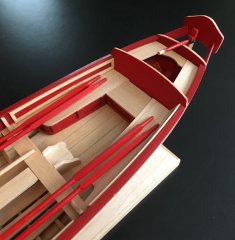
The hull is finished! After sanding to an acceptable texture, I primed and painted it using Model Shipways primer and white, thinned and with several coats. This sealed off any remaining tiny gaps nicely but the planking can still be seen.
I rebuilt the rudder to get proportions I found more pleasing, and painted that too. It won't actually be installed until much later, but it's done.
And two more views of the hull from bow and stern:
I had intended to plank the main deck next, but changed my mind. I'm going to build the cylinder timbers and wheel supports next, because those will inform how I lay out the deck and superstructure. Plus, I've dealt with enough planking for now.
Thanks for reading!