Check out our new MSW Sponsor Innocraftsman
×


jbshan
-
Posts
1,222 -
Joined
-
Last visited
Content Type
Profiles
Forums
Gallery
Events
Everything posted by jbshan
-
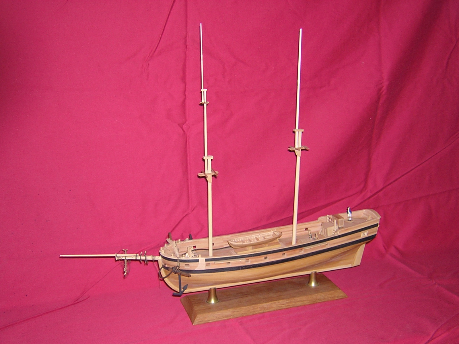
 I didn't necessarily follow Clay's practicum. It was enjoyable working with the hardwoods provided by dlumberyard; swiss pear, maple, boxwood, apple. When you pick it up you know it ain't basswood.
 -
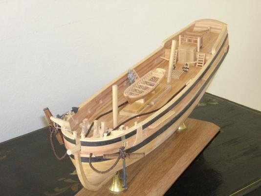
I have a series of pics taken while work was in progress which illustrate techniques I have not seen in other logs. I also have not seen, even after a search of the site, this particular model. I would be happy to post these pics, with comments of course, in sequence if others think it would be helpful. Past this point, I have built tops. There is also a scratch-built yawl, visible on deck, done in a novel manner.
-
Seeking information on determining load waterline
jbshan replied to trippwj's topic in Nautical/Naval History
"Simpson's Rule" That's certainly the first half of the equation, but they then have to get the weight of the ship, guns and stores, etc. correct, enlarging the hull if necessary. The first US ships of the line sat fairly low in the water, if I recall, so the ports were too close to the water, and those were 1820 and later. I have seen methods where you mark out squares of a curved enclosed shape, then little squares, then littler squares, until you have covered all of the shape, to measure the area. Is this similar? -
Seeking information on determining load waterline
jbshan replied to trippwj's topic in Nautical/Naval History
While she did indeed capsize and fill through the ports, Mary Rose was some 25 years old at her sinking, so not that totally unsuccessful of a design. Just to keep the record straight. -
Seeking information on determining load waterline
jbshan replied to trippwj's topic in Nautical/Naval History
It has always seemed to me that they made a best guess based on experience during the design phase then, when a ship was determined to be ineffective a fix was made. Vasa was the extreme where it was not possible to bring her back for the fix based on sea trials. The problem persisted up into at least the mid-1700s, ships being lost at the battle of Quiberon Bay (1759?) because of hauling up their lower port lids. Supposedly a yacht for Queen Victoria was so altered while being constructed that she capsized still in the dock. If a courtier suggested the Queen might want to listen to a fiddler playing chanties atop a capstan, a capstan was added. Finally so much was added that stability was lost. I suspect they had to wait for calculus to be invented before they had any sort of chance to work it out on paper beforehand. -
You oughta see it in person. My chin left a dent in the table when I saw it.
- 382 replies
-
- 4
-

-
- sovereign of the seas
- carving
- (and 1 more)
-
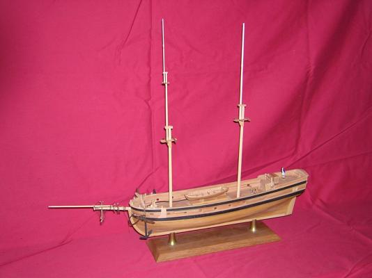
Here is the bows of my Lexington model. The port anchor is hanging from the cathead. The starboard is hoisted up and lashed to the rail. Lexington is only a little bigger than your vessel and of precisely the same time period.
-
Your splash boards look to me as if they could very well be extensions of the hawse timbers and top timbers. Where the hawse holes are would be between two timbers, with half the hole in each timber.
-
They're pretty good at 'healing' a knife cut, but saws and drills leave a permanent defect. I've used both blue and green, from the art store, Stadtler and Alvin brands, 12 by 18 inches.
-
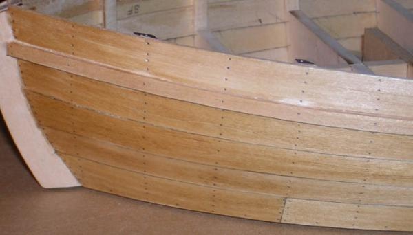
I have four in the sheer strake, one in the wale, which is what I see in the Smith 3D scans. Other places I have three and they have four, yes, though toward the ends of the hull, where the plank gets wider I have more, to keep the number of nails per foot about constant. I, too, have to decide what to do about the stove/hearth location. We KNOW it was on the middle deck at one point (when she sank) but only can suspect at a cockpit location.
- 259 replies
-
- 2
-
-
- Gunboat
- Philadelphia
- (and 1 more)
-
I'll bite. Here's mine; show me yours.

-
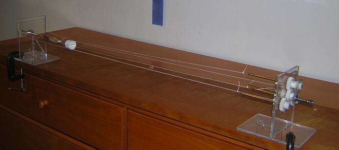
Glad it made sense to you, Nick. At present my ropewalk is clamped to a board about four feet long. If I go to a longer walk, all I have to do is reset the two strings supporting the top to the new length. I have used this setup to worm anchor cables also; that can approach the proverbial mare's nest if things get out of hand. :-) I think it could be used for serving, but haven't tried that yet. If the swivel at the tailstock end is sufficiently free I don't know why it wouldn't work.
-
PLANKING STEAM TANK
jbshan replied to Walter Biles's topic in Building, Framing, Planking and plating a ships hull and deck
I've just been reading about planking a ship in 1760. Their box was very similar to the USN one, although made of wood. I'm thinking they were repairing wooden ships' boats with that 1 X 2? My book talked about one hour per inch thickness, plus an hour for luck. Oak plank, up to 9 inch thick, up to 60 feet long. A bit different animal. -
Mark, my head and tail stocks are held to the board with c-clamps. Length is variable. Can you cut your commercial one and extend it?
-
I ran the line from my tailstock out and to a weight, in the final version. My top is suspended from two lines running the length of the ropewalk. Pics and some text are here: http://uvsmgshipmodelguild.wikispaces.com/A+Ropewalk There are links also to model ropewalks and real ropewalks. It is fascinating to watch the rope 'make up' full size.
-
As a long-term project, go to Boston. There is a large scale model there you can take a look at.
- 13 replies
-
- 4
-
-
- USS Constitution
- Old Ironsides
- (and 2 more)
-
Got it! A painting, John Clevely the Elder. 'A British sixth rate ship at Deptford dockyard in the 1770s.' illustration in War at Sea in the Age of Sail, Andrew Lambert. pp 36-7 The jack actually is flying from a staff set up just behind the figurehead since there is no bowsprit, etc. The commissioning pendant has red white and blue stripes. The vessel is on a launching cradle on the ways. She has a coat of white below the waterline. The author is of the opinion that she will be brought into the dock in the foreground of the picture for coppering.
-
It's a picture in one of the six books I've been reading lately. Patience. :-)
-
I found one more. A sixth rate, Jack at the jack staff, ensign at the ensign staff, a pole in the main mast partners with a commissioning pendant, nothing at fore or mizzen locations.
-
It helps to keep your plank less than full length as well. There will be less curve needing to be cut if you stick to traditional lengths. Note all the butt joints on Chuck's model.
-
Another instructions 'author' I have not seen mentioned is Ben Lankford. He did the plans and instructions for Model Shipways' Niagara. There are several sheets of drawings and details, plus the usual layout sheets of where the parts are. If you go from sheet to sheet, THEY FIT EACH OTHER!!! 6.5.1/4 on one sheet is 6.5.1/4 on all of them. That's very hard to do. I'm sure he must have done other models, and probably to the same level; I can't recommend Niagara as a first planked model. Jim Roberts' 'Planking the Built-Up Ship Model' is one of the best for that aspect. Model Expo usually has it. BlueJacket rates their line into about 9 different grades of difficulty. You should be able to find something there. Supposedly they also have staff to answer questions from purchasers of their kits. Keep looking, you'll find what you're looking for eventually.
-
Trying to identify an inherited solid hulled model
jbshan replied to Beeman911's topic in Nautical/Naval History
There is still value as a 'vernacular' or 'folk art' piece, especially with your family connection. Your plans for a display seem sound. I would suggest just going ahead and restoring the rigging as best you can work out. There are lots of books dealing with ships of this period which I am sure this forum can advise you with. -
The wooden rails in the tops of the brackets was one variation used, according to the literature. Loops or eyes with rope was another as seen on some of your photos.
- 732 replies
-
- 1
-
-
- constitution
- model shipways
- (and 1 more)
-
Trying to identify an inherited solid hulled model
jbshan replied to Beeman911's topic in Nautical/Naval History
I did a quick look through Chapelle's 'Search for Speed Under Sail'. There are 'China Packets' and 'Clipper Ships' of the late 1840s and early 1850s with that hull form and pointed deck at the bows. The Clippers didn't burst forth fully formed from the brow of Donald McKay, there is a traceable development. Where the lack of hatches and large deck houses came from I cannot say. Obviously you would have needed a way to get the cargo below decks. -
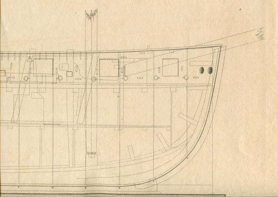
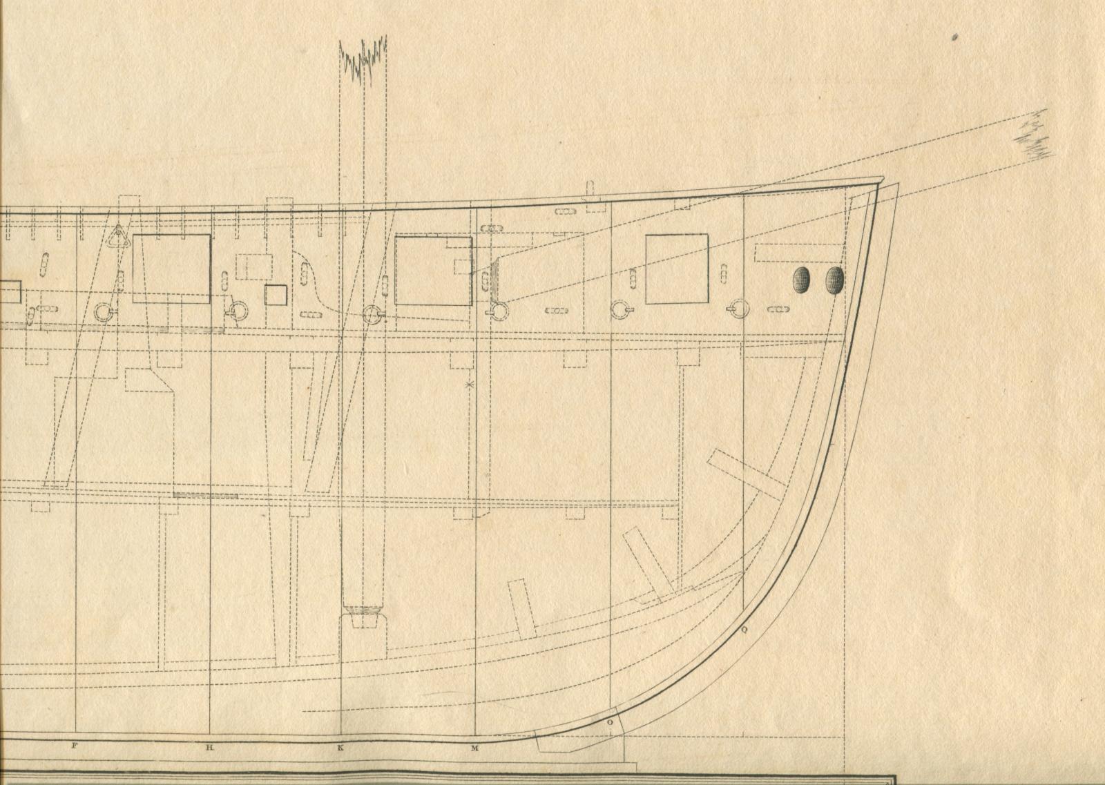
I guarantee that the plates for the Naval Architecture are 16 X 46 inches. My copy has an inscription inside the front cover dated 1812. The plates are exquisite copperplate on very heavy stock. I know it isn't the volume in question, but I offer the information to perhaps give some idea of what layout the original may have. Here is a scan of a portion of one of the plates.