xken
-
Posts
841 -
Joined
-
Last visited
Content Type
Profiles
Forums
Gallery
Events
Everything posted by xken
-
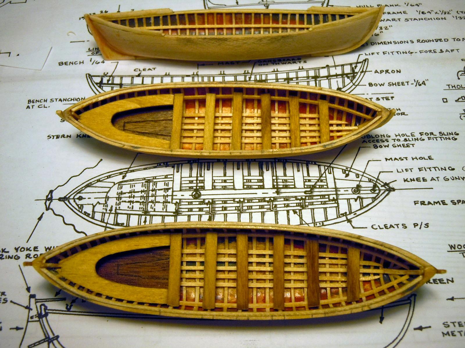
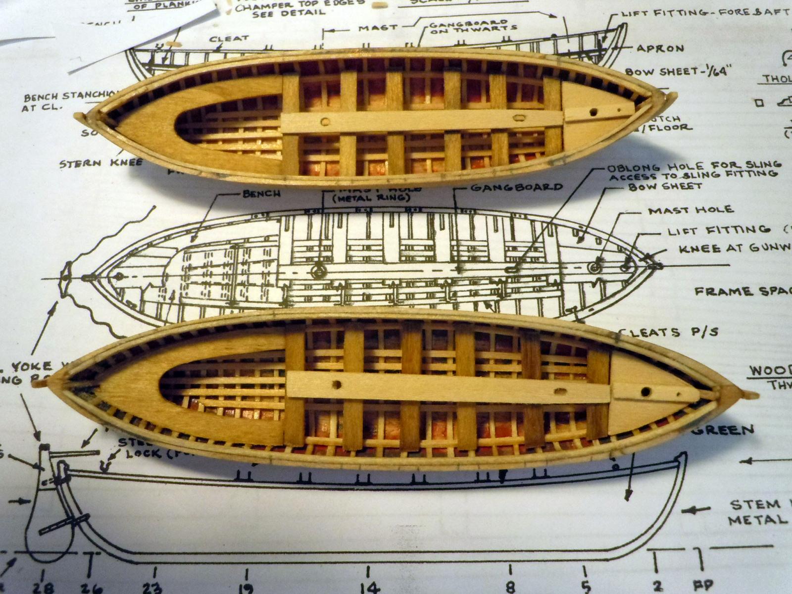
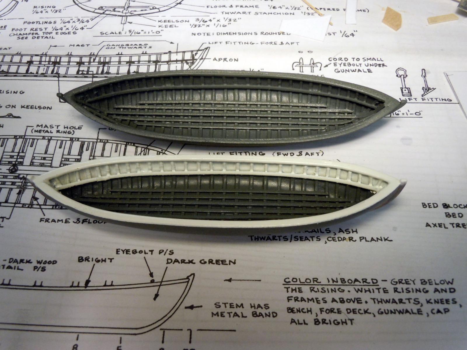
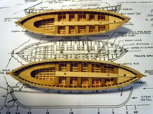
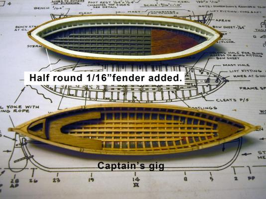
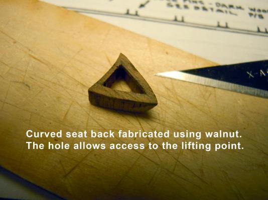
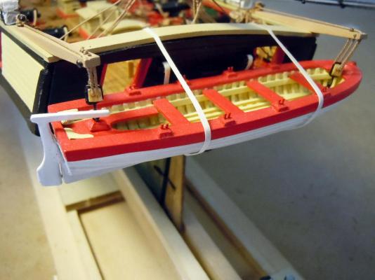
 I am working away building the four small boats simultaneously, I finished the wood stand for the pinnace and moved on to the two whale boats and the captain's gig. Here are all three in various stages of innards being added. The gig is at the top with the two whale boats below. The sole is walnut and the bench and thwarts are stained basswood and will remain bright. Here the gang board and forward aprons with the mast holes and location for lifting eyebolt. This shows the start of painting. The plans say grey so I used grey primer and then sprayed it with clear to prevent marring it during masking. I tried to find a reference to the shade of grey but could no find any showing the inside of the boats. The white was sprayed Satin White. The top is the first whale boat with the half round bright fenders added and showing the walnut sole in place. The captain's gig has the walnut front apron, bench and curved seat back with access hole to the lifting point. The hole would be covered with grate. Here is a detail of the curved seat back; this was easier to fabricate even at it's small scale than I thought it would be. Now back to the small boats, the nice thing is being able to bounce around from one to the other.
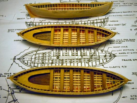

-
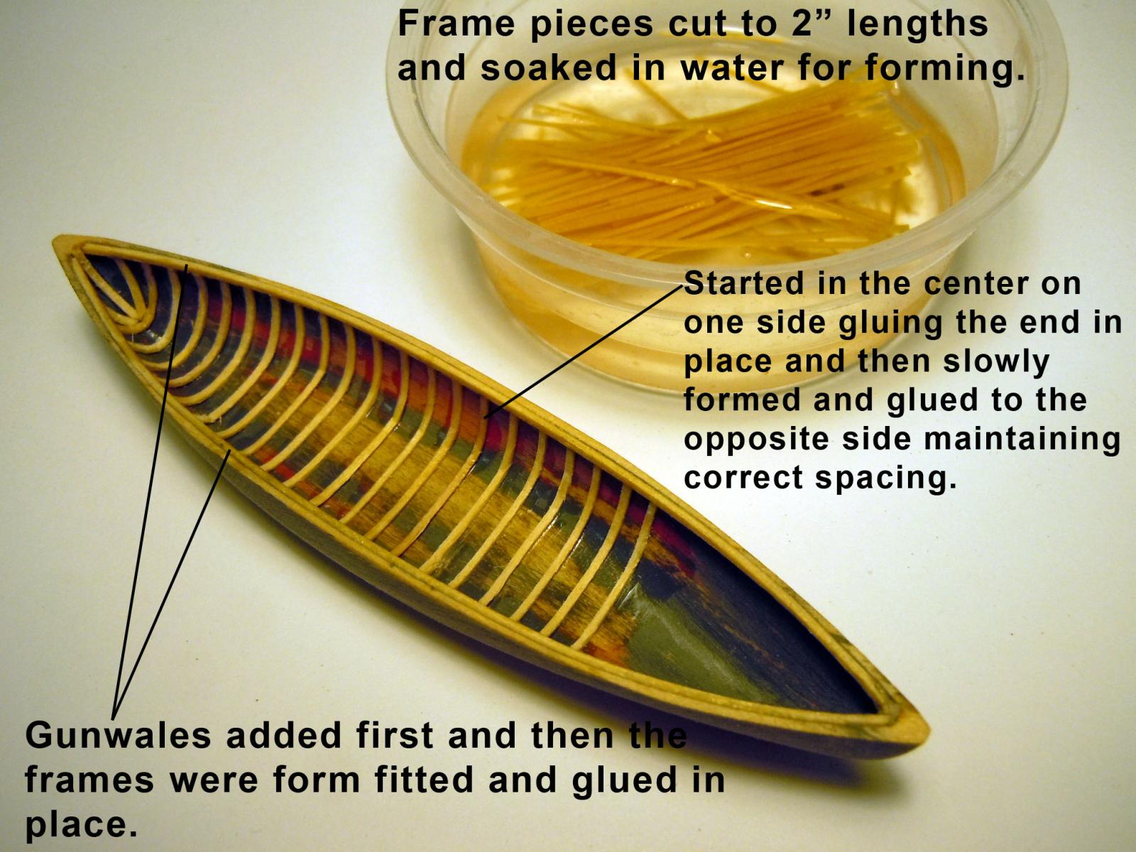
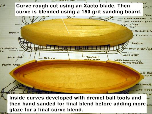
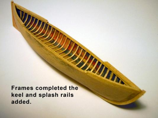
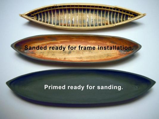
A quick in progress update of building the captain's gig and whale boats. Similar steps as the pinnace except smaller scale. I started with the gig first because only one is needed while there are two whale boats and the gig is the smallest of the three. The three insides were developed first before the bottom parts was added then the bottom exterior was rough cut with an Xacto blade and then sanded to final shape. Then the inside bottom was shaped using different sizes of ball tools and then final sanded by hand. Next glaze was added to blend the curve of the sides to the bottom. Here the frames are being added. I cut the frames from Midwest #8003 by cutting 2" strips in half. They were then soaked in water for hand forming. First I would take the wet frame and carefully develop a curve using the smooth part of an Xacto blade handle. Then the curve part end was glued in place and slowly formed into the hull and very carefully CA added; the opposite side was cut off against the gunwale and glued in place. Adding these frames is a slow tedious process that will try one's patience. Here the frames are completed and the splash rails and keel added. The stern end was sanded flat and both stern and bow ends were traced to 1/16" sheet stock and cut out and glued to each end. A strip was added between the two ends and sanded to blend the completed keel. The splash rails were cut to required lengths and soaked in water to form to the gunwales at each end. Once they were dry they were then sanded to blend to match hull sides. The ends were then filed to shape using a round needle file. This picture show the various stages as I work the three boats at the same time and moved back and forth between them. The gig has the risings added ready to add the rest of the internal parts. Excuse the camera distortion, the bottom two are actually the same size whale boats.

-
I wish to thank all of you for your help, kind words and encouraging compliments! I have moved on to building the USS Constitution having learned many lessons on ship building with this my first build. I still have a great deal to learn and add to the skills I already have and use.
- 440 replies
-
- 6
-

-
- niagara
- model shipways
- (and 1 more)
-
Greg, No I use Staybrite solder and flux, softer than Silver solder but stronger than plumber solder 50/50 or 60/40. I buy it at the local welding supply shop by the roll and container of flux, much more cost effective than hobby outlets. I use the 1/32" size. The shop may have to order it for you since it is not a standard shelf item. Here is a link, hope this helps. http://www.harrisproductsgroup.com/en/Products/Alloys/Soldering/Lead-Free-Solders/stay-brite.aspx
-
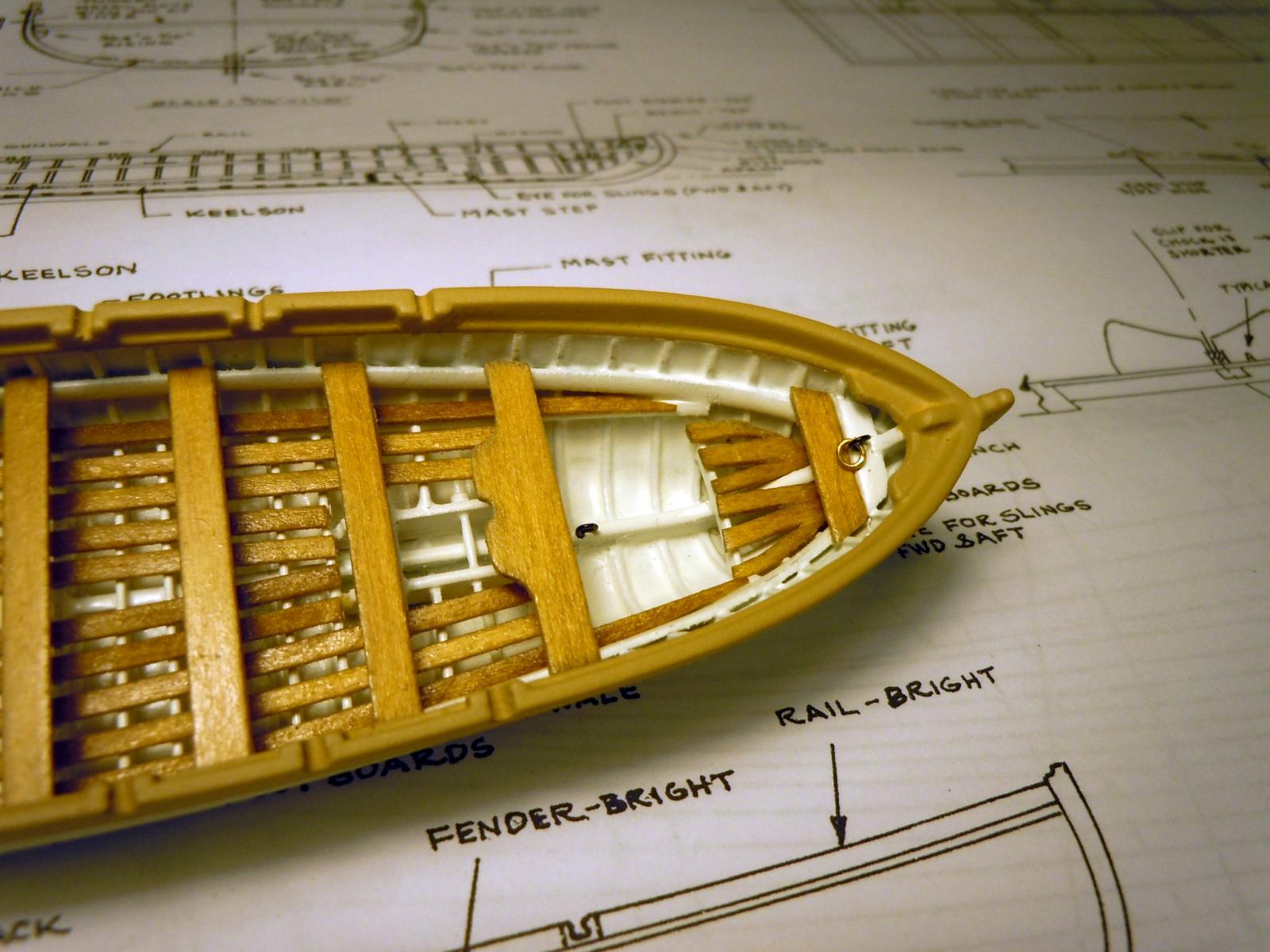
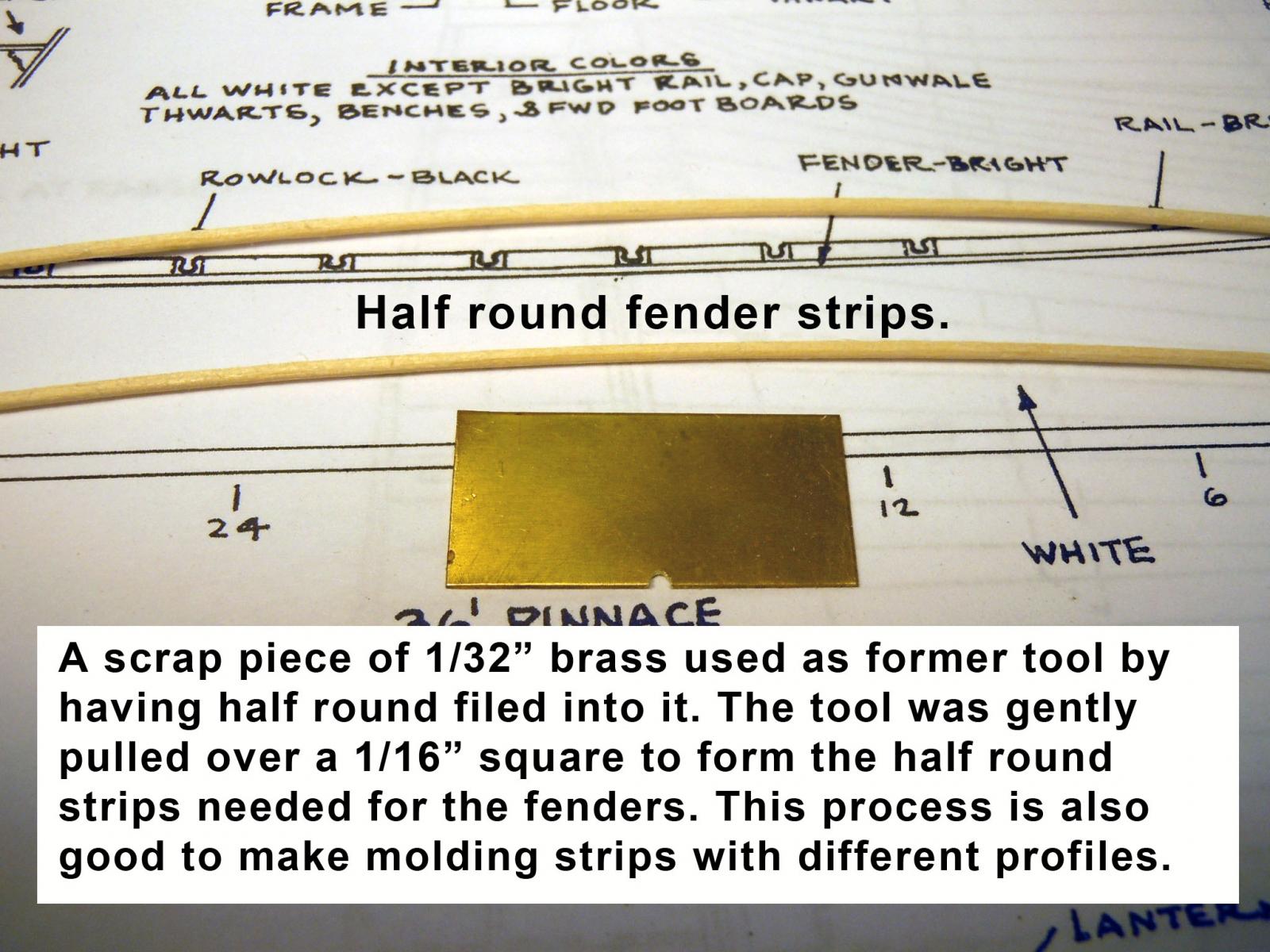
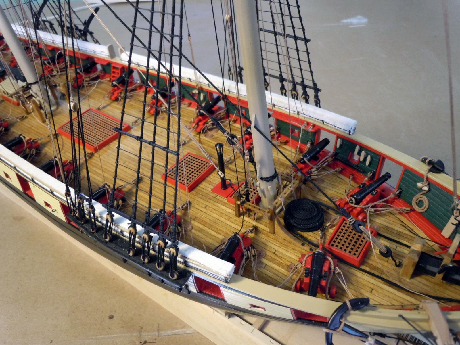
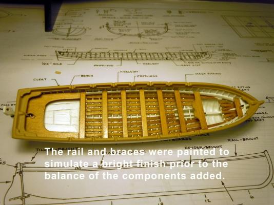
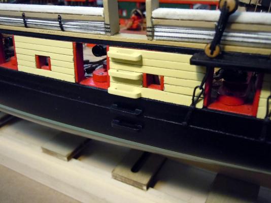
Thank you all for your kind words and encouragement! They make the extra effort to document worth doing. I am doing it more for those who are new to ship building like myself than those of you more experienced. Here are two images of the finished paint work using Krylon semi-gloss white. Here I have added the dried, stained and clear coated footlings upon their supports. First I masked off the inside and outside of the hull to define the bright rail. TIP: spray first with a couple of light clear coats to seal the edges and reduce the chance of the color coat bleeding through the edge of the masking tape. Once the paint was dry I then added all the rest of the bright parts and lifting rings. Here are a couple of close up of fore and aft. In hind sight the next time I will use individual planking for the sole rather than scribing. Here is the set up for soldering the hinges; if wanted to make functional after all the finishing it would be sawed into two parts through the center. In this case they are fixed. Next while waiting for things to set and dry I made a molding cutter by filing a half round into a piece of 1/32" brass. Then using 1/16" square basswood strip I slowly and carefully scraped on a hard flat surface the half round profile for the side fenders. I have used this to make accent molding for other projects as well. These will be added to the side following the bottom edge of the buff paint. Enough for now back to work. I have honey-dos this afternoon.


-
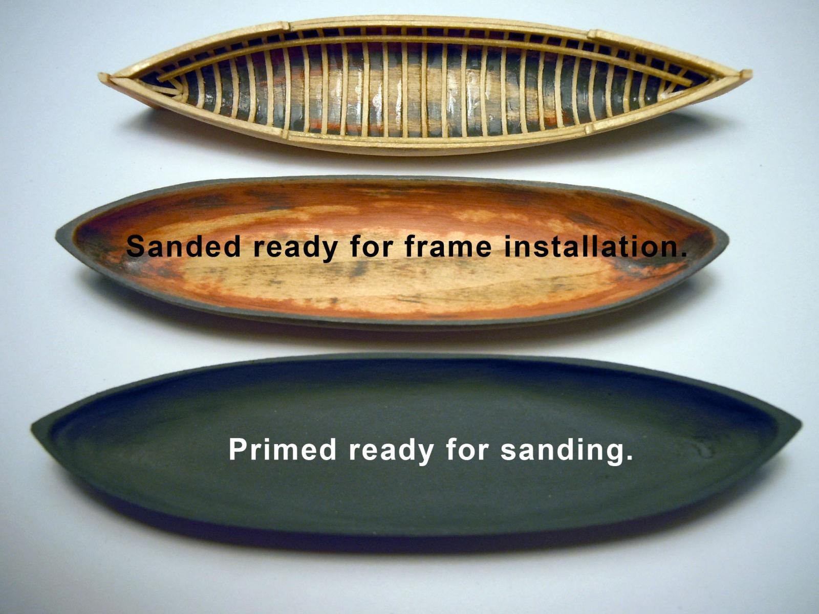
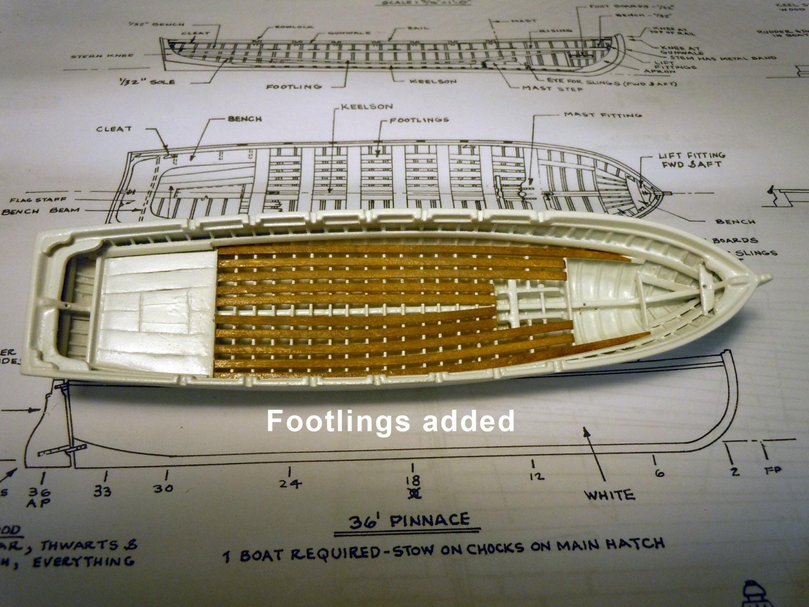
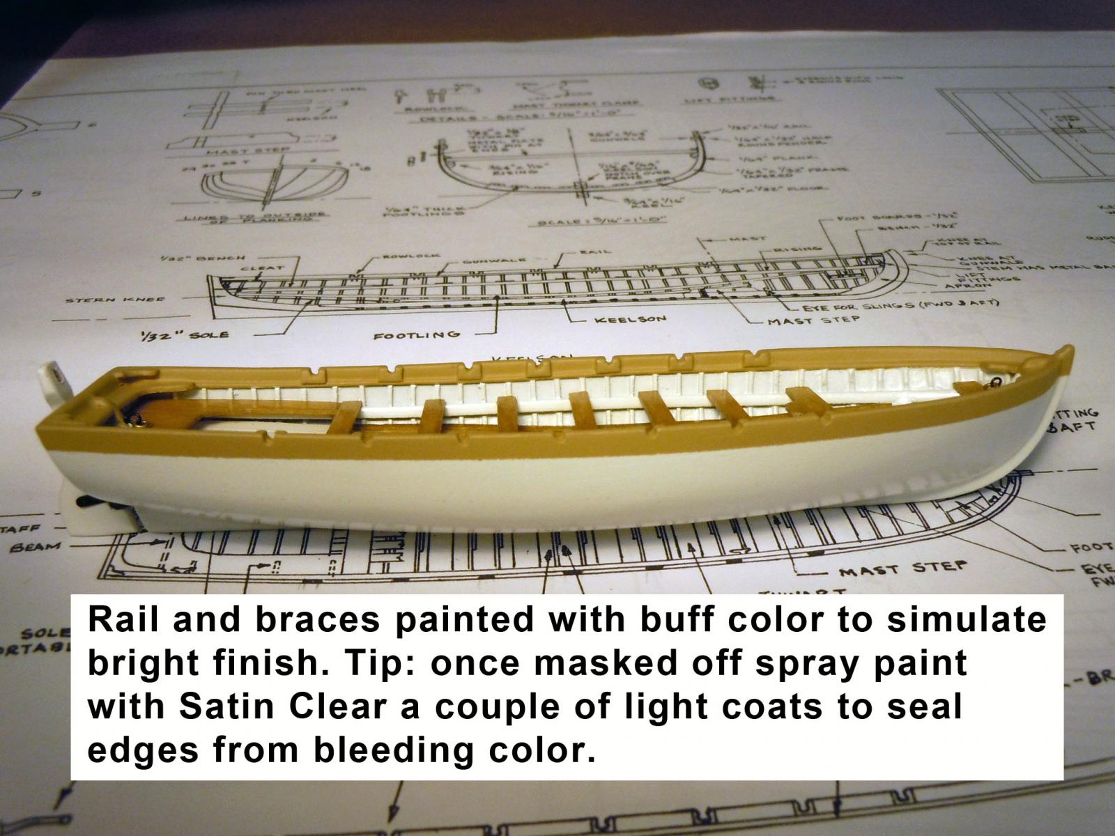
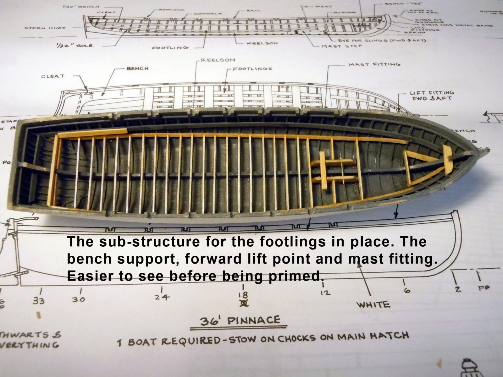
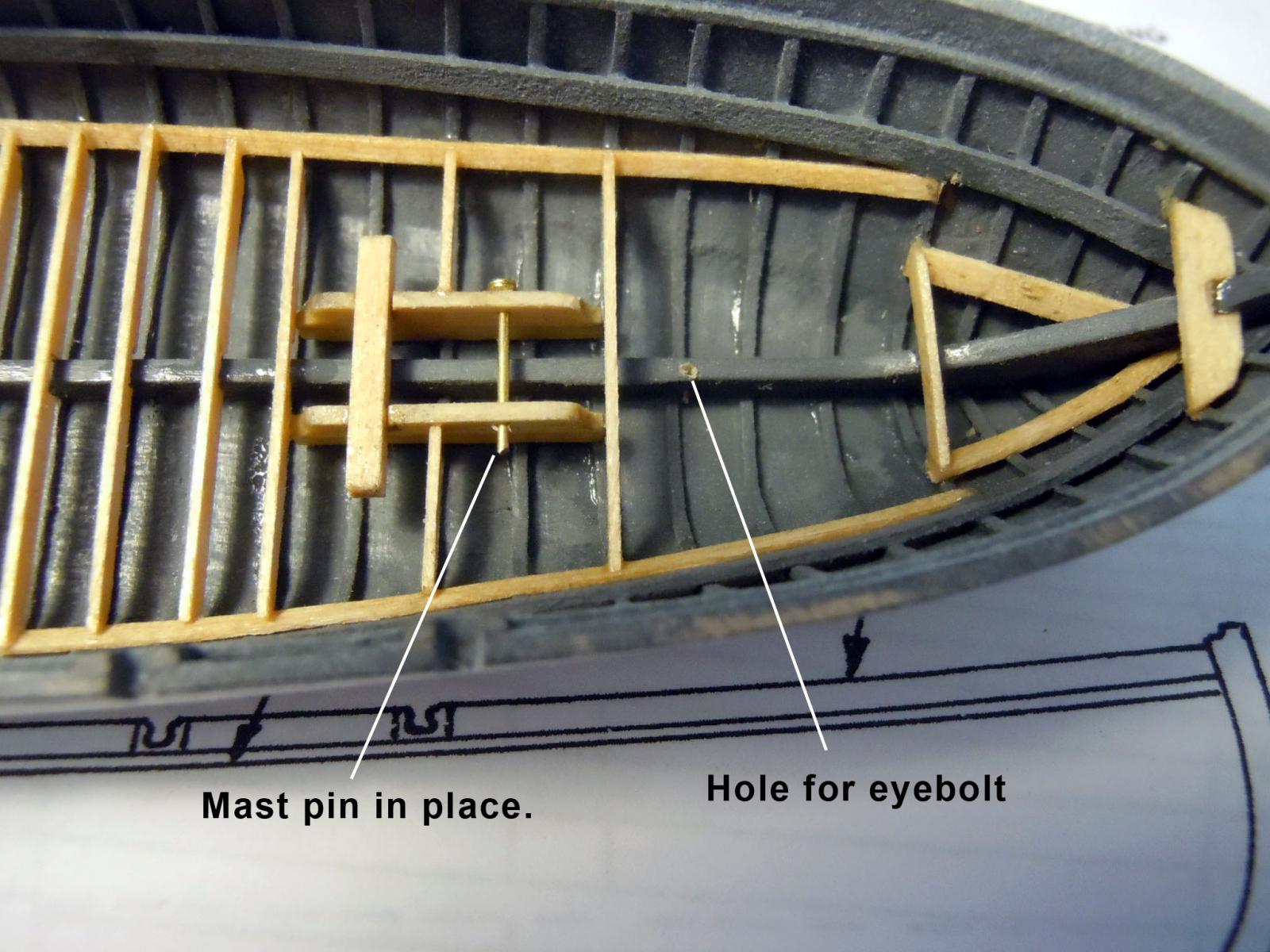
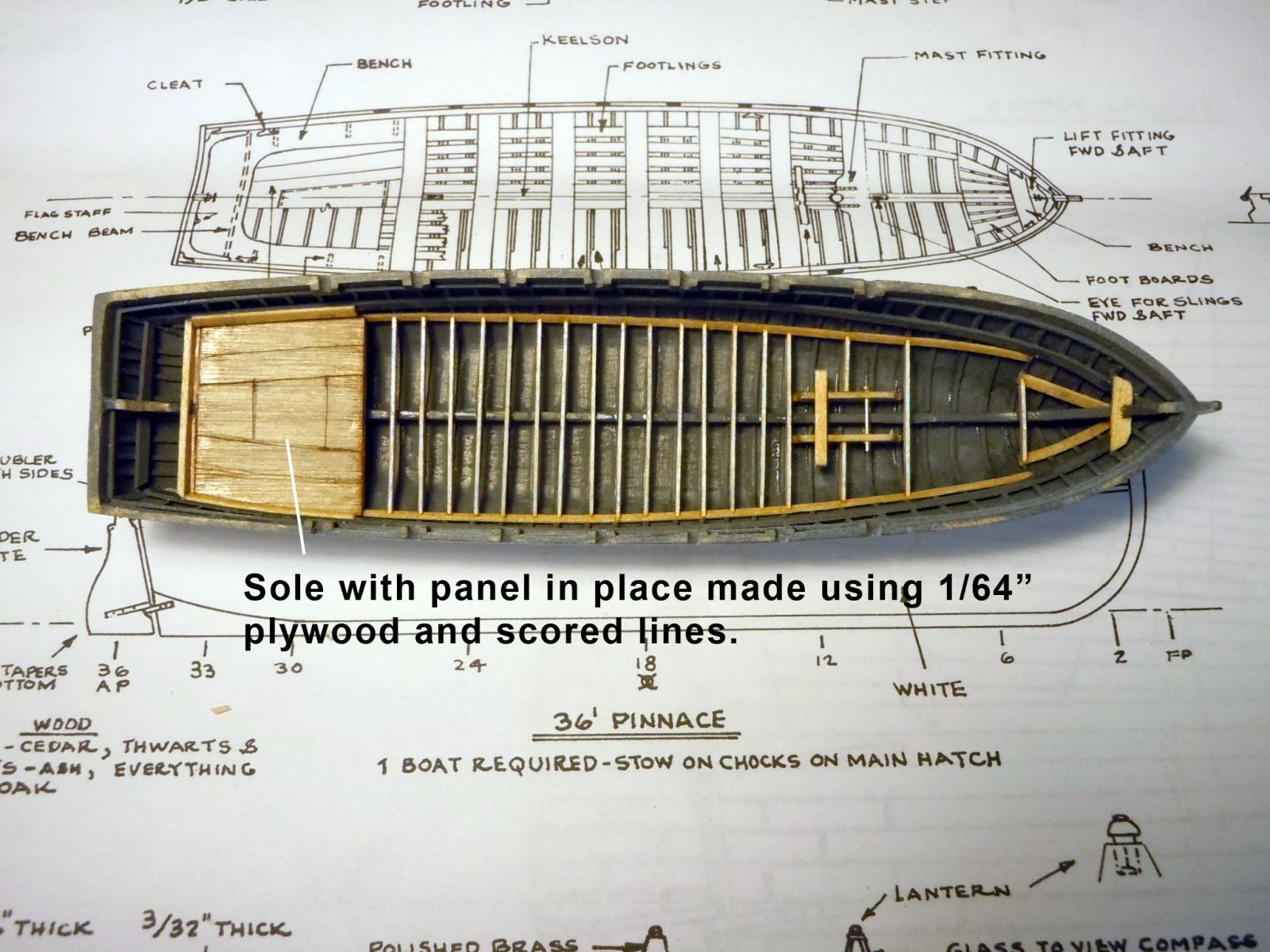
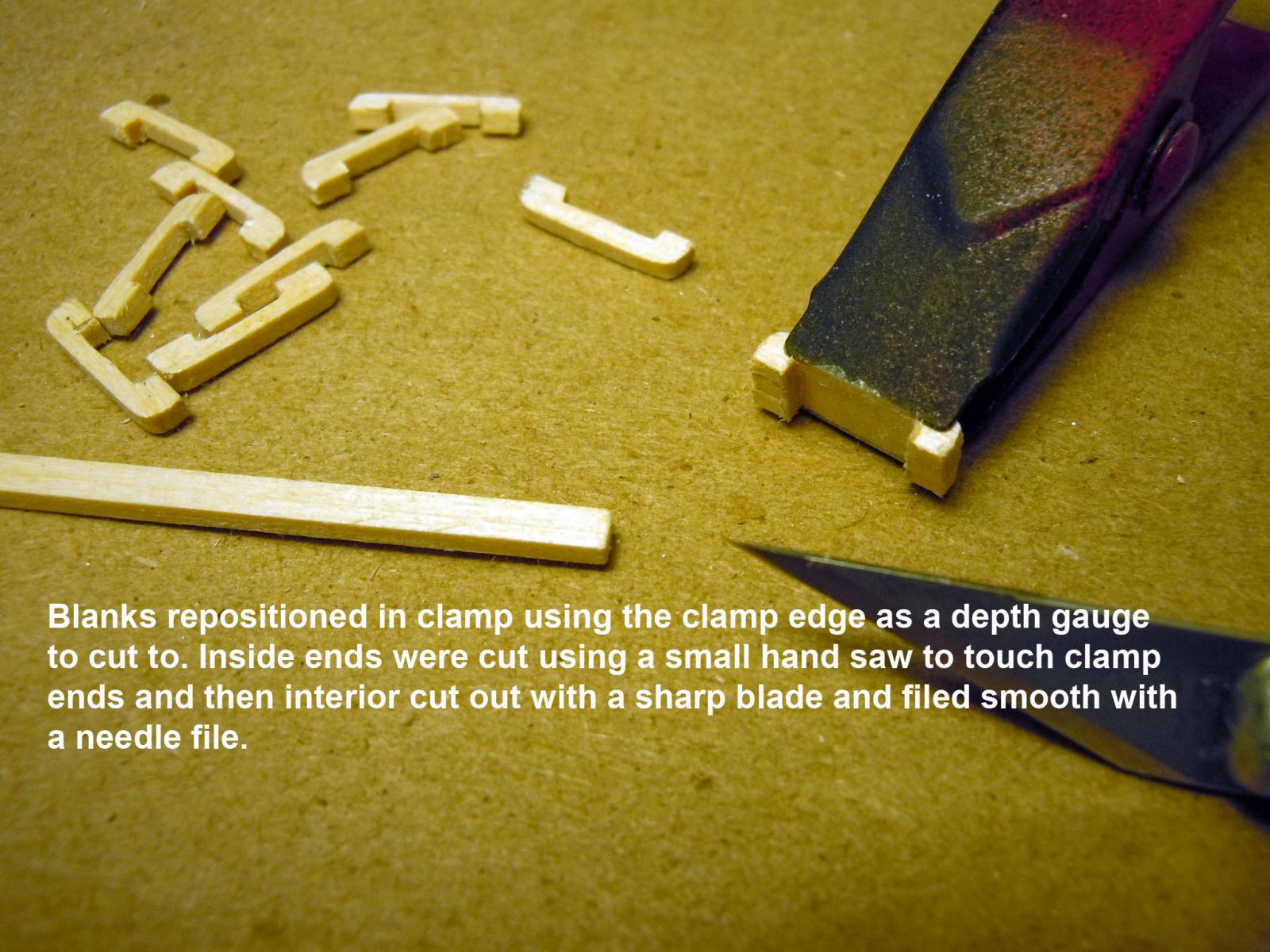
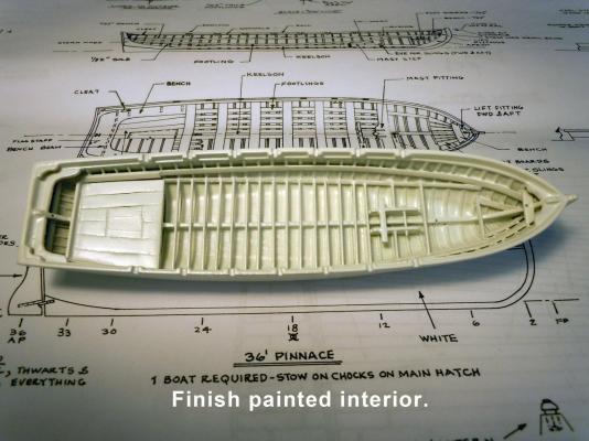
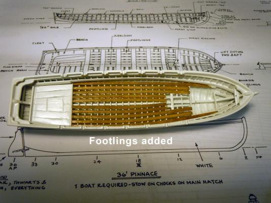
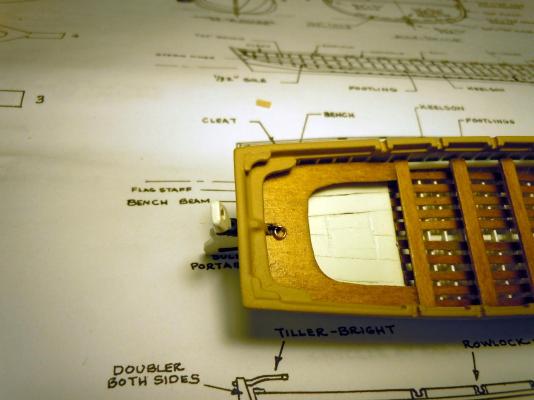
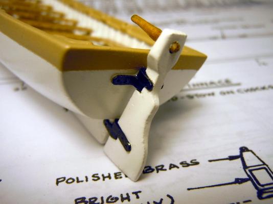
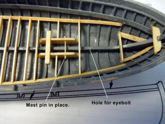
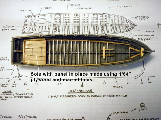
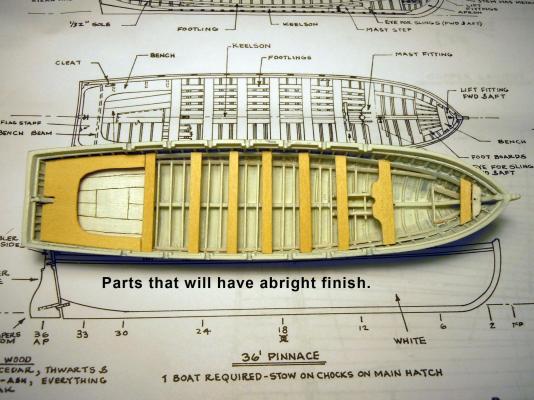
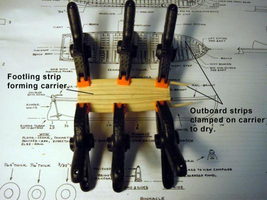
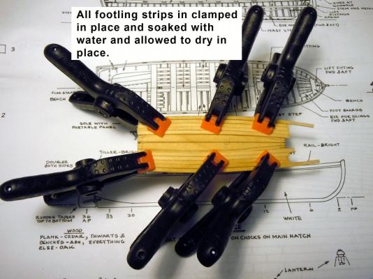
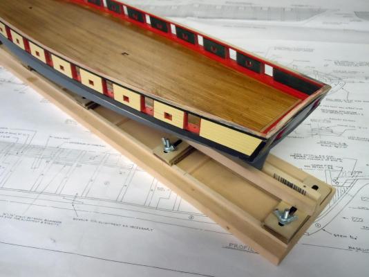
Well I primed the pinnace and while waiting for primer to dry I looked over the plans and tried to sort out the next steps. The side and top views do not seem to match each other when it comes to the footlings and the keel; so I ventured forth with common sense. Here I have added the internal structures based upon the side view. Here is a closeup of the mast fitting. Here is the sole added and I used 1/64" plywood to conserve space and scribed the joint and panel lines. I then primed again using white primer for two reasons; first the final color will be white, second for the exterior hull sanding down will reveal high and low spots between the white low and grey the high. However, gentle sanding is needed so as not to break through the primer coats to the wood. Also I fabricates the bench and thwarts which will have a bright finish. Here I am edge forming the footlings which have a slight curve and a bright finish. First I cut a carrier the shape needed fore and aft and side to side using a 1/32" thick piece of wood. Next using Midwest Scale L item number #8003 .0208" x .0625" and soaking with water slowly and carefully edge formed just using my fingers. Once formed the side pieces were clamped to the carrier to dry and set. Once all were formed and clamped in place on the carrier they were all soaked again with water and let to dry and set overnight. Now back to work.

-
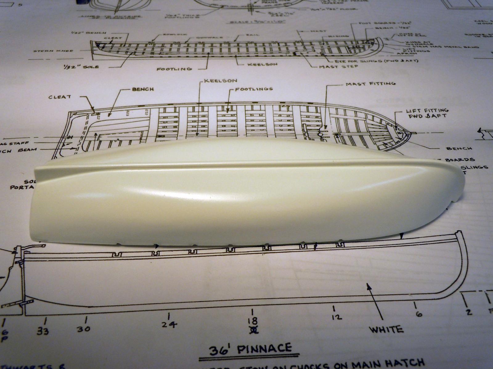
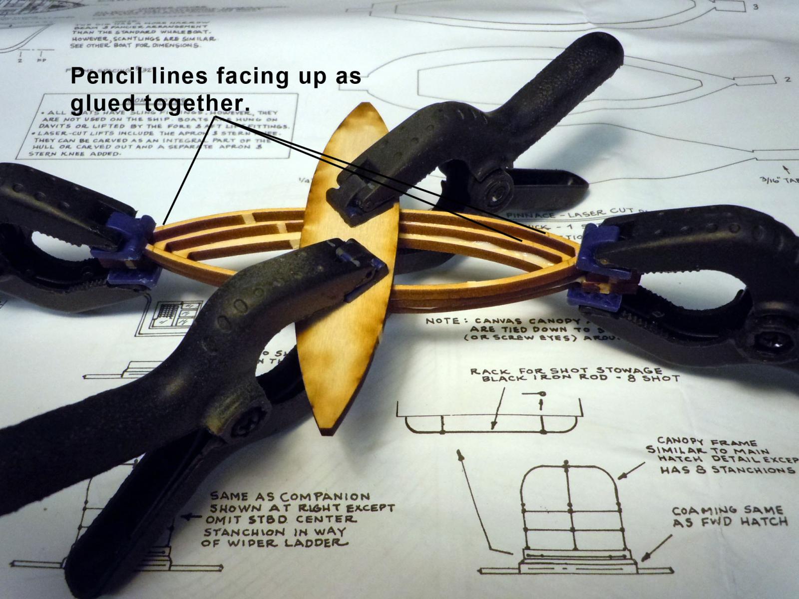
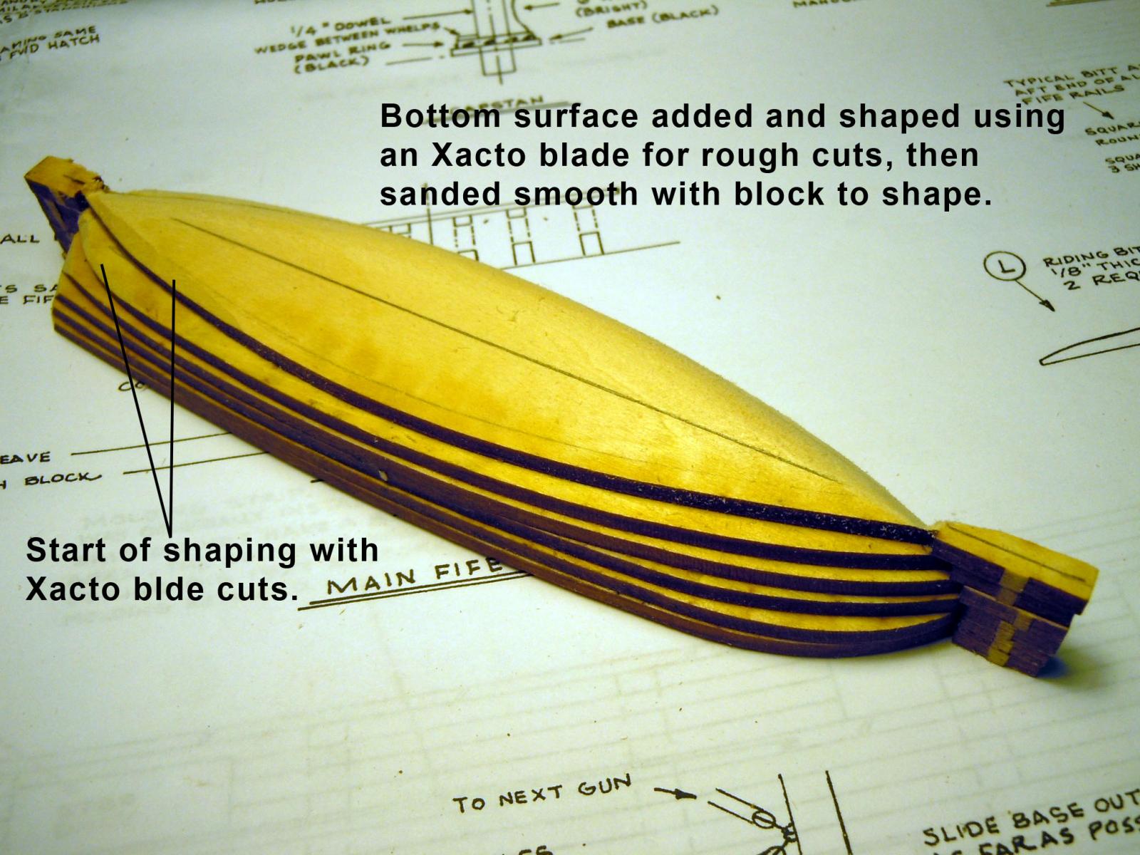
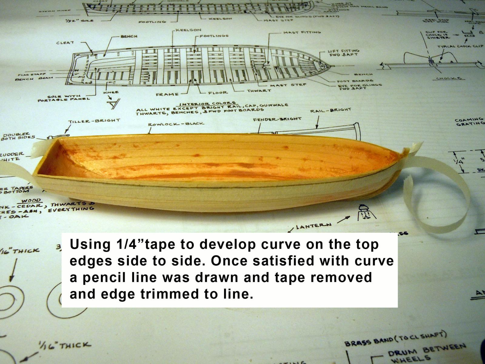
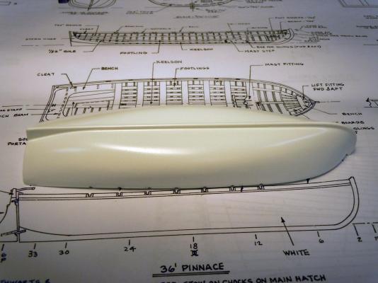
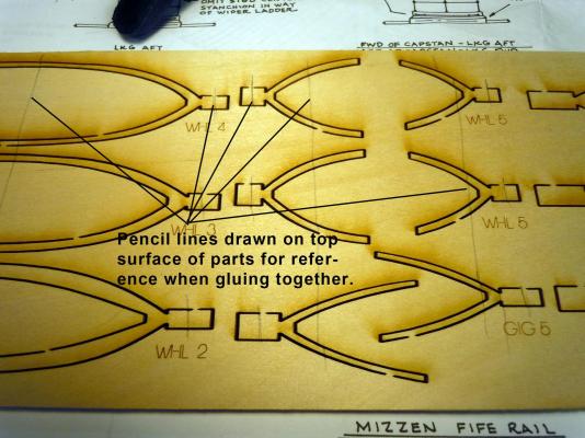
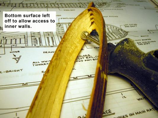
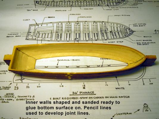
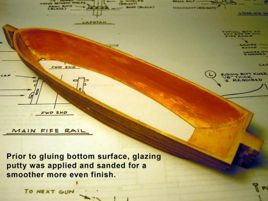
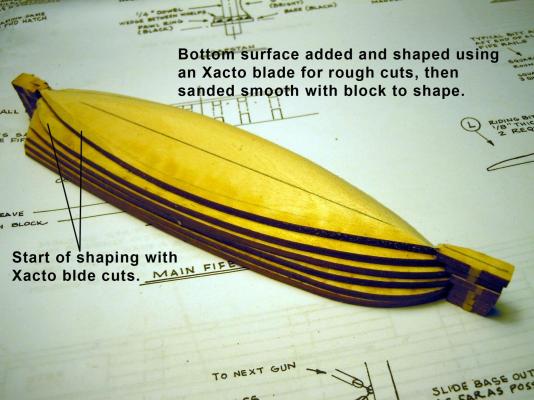
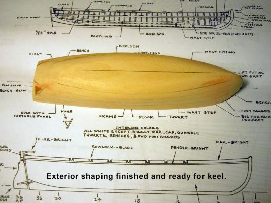
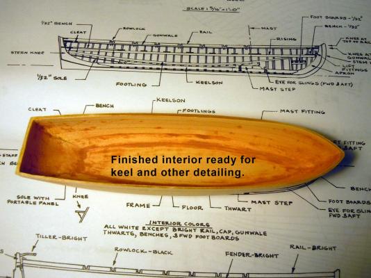
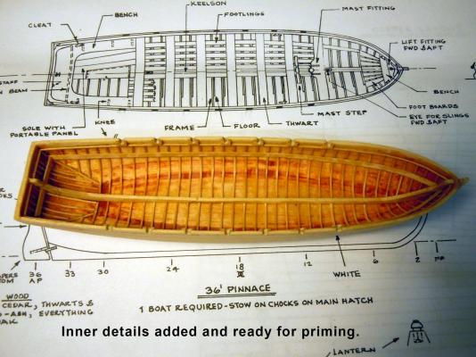
I am off and running to continue my education of model ship building and hopefully on this one I will add sails. Like my Niagara build I will start with the small boats which are mini model kits in themselves and that my two young granddaughters like looking at the "baby boats". They are 2 and 4 years old. I will skip the presentation of the box and contents since others have done it so well. I am starting with the pinnace the larger of the four. I started by marking the top surfaces of the laser cut parts before removing them from their parent sheet. The reason is that the laser cutting process burns a slight angle in the wood and when layering and gluing together you can use this angle to your advantage and avoid super thin areas. I glued all the layers of all the boats together minus the bottom layer. I used the scrap center as a clamp surface to provide even compression. Here is the reason to leave the bottom layer off and allow clearance to work on the inner walls. Here is the finished up inner walls rough cut and then sanded. Next I added sparingly automotive glazing putty to the inner walls for additional smoothness. This glaze dries quickly and is very easy to sand. Think of it as a thick layer of primer filler. Here is the finished exterior Here the bottom layer was added and shaping started by rough cutting with an Xacto blade, sanding block and sanding sticks. Here is the finished exterior ready for the keel. Here is the finished sanded interior ready for keel and other details. First I had to address the bow to stern sidewall curve which I developed using 1/4" masking tape, then marked the upper edge with a pencil and removed the tape and trimmed to the pencil line. Here is the interior with all the details added that will be painted while the rest will be bright stained finish. The exterior keel has also been added. The ribs are .0208" square Basswood Midwest Scale Lumber item number 8000. I have used their micro cut lumber for years on airplane builds. Next the pinnace will be primed and sanded and readied for paint per the plan scheme.


-
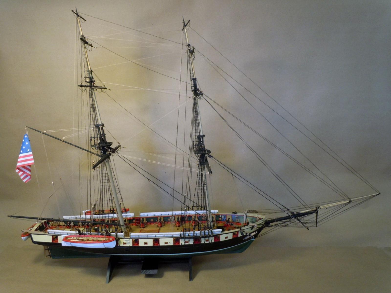
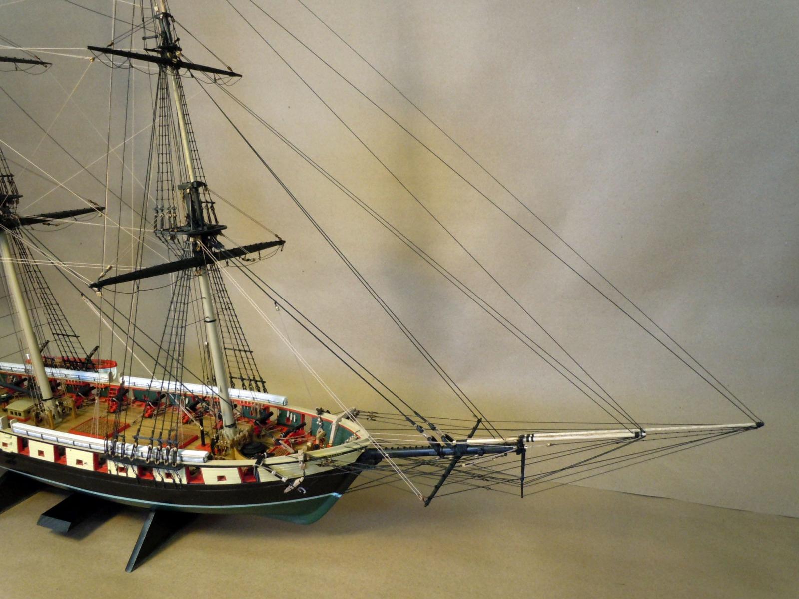
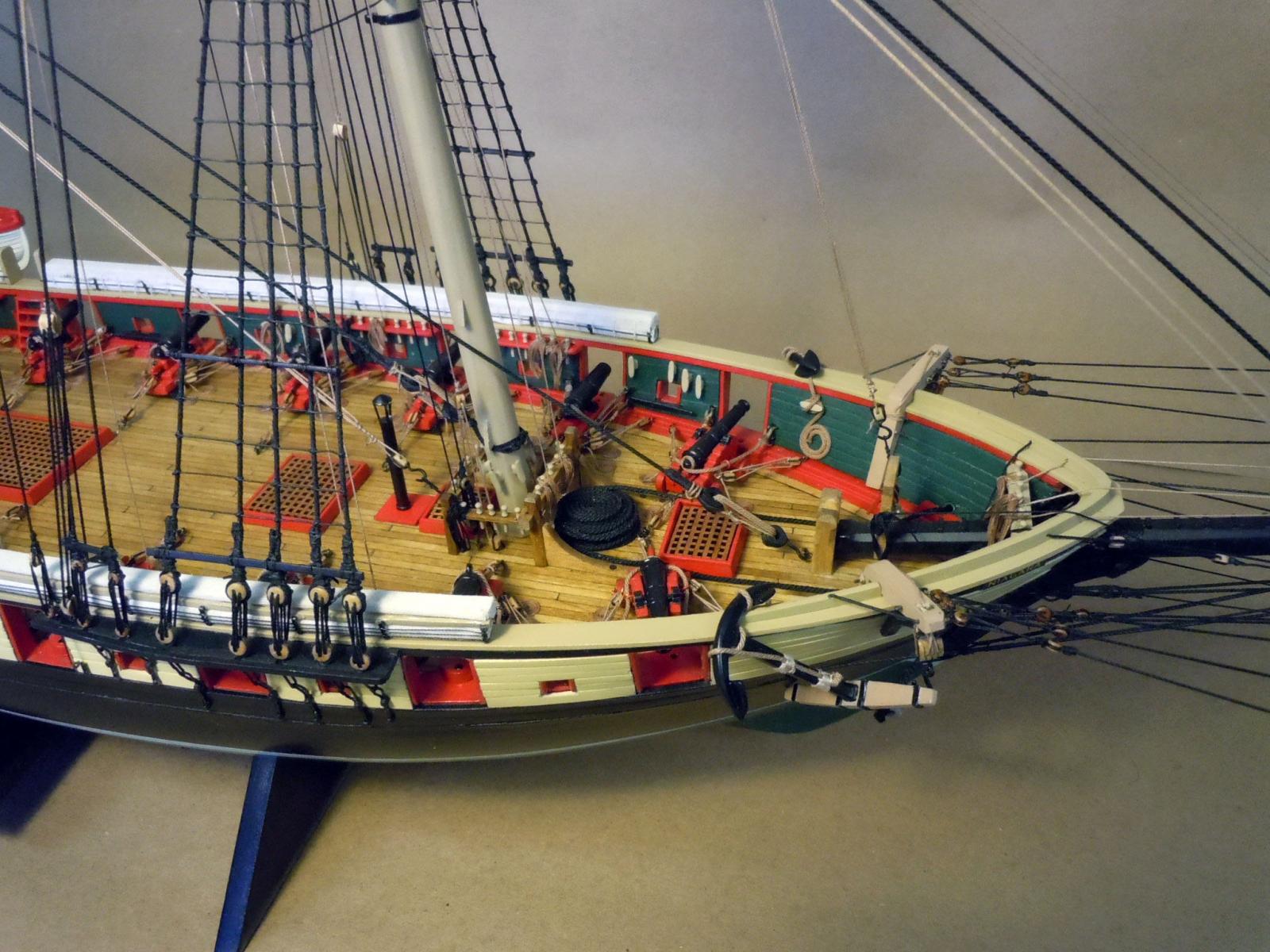
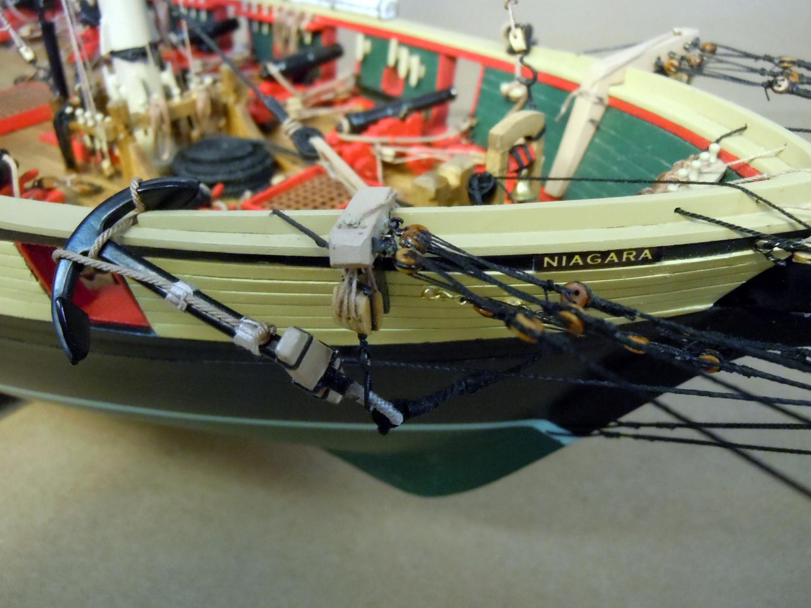
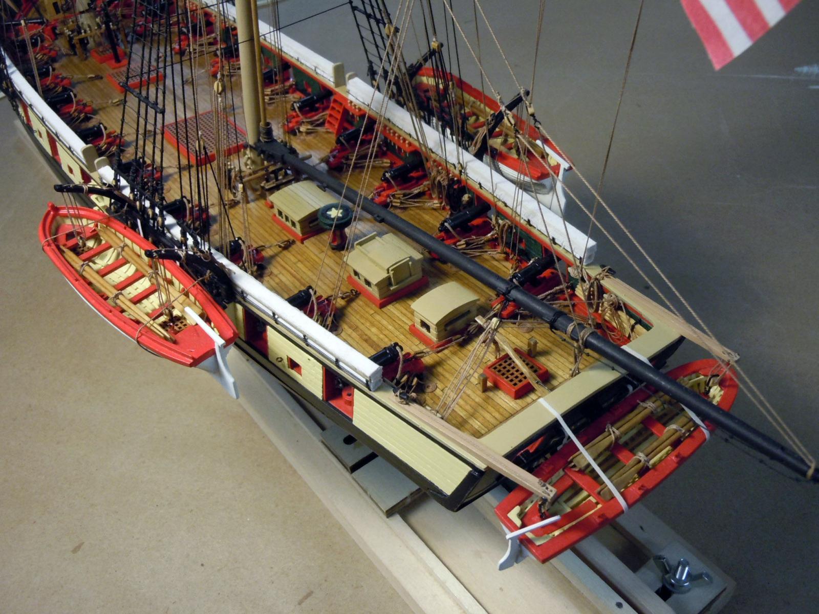
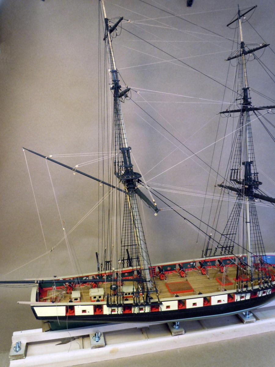
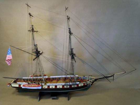
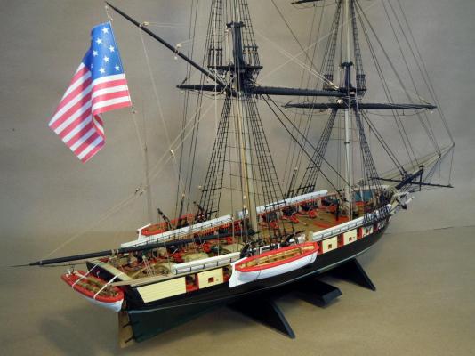
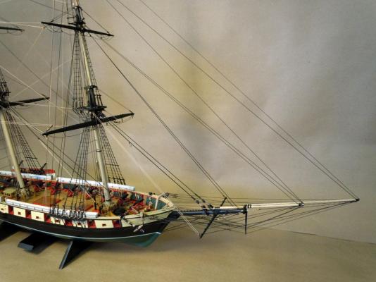
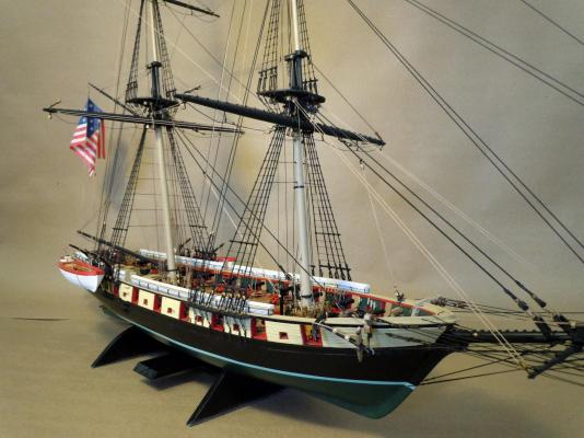
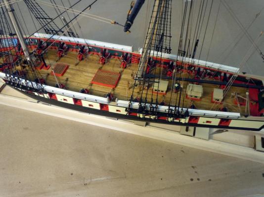
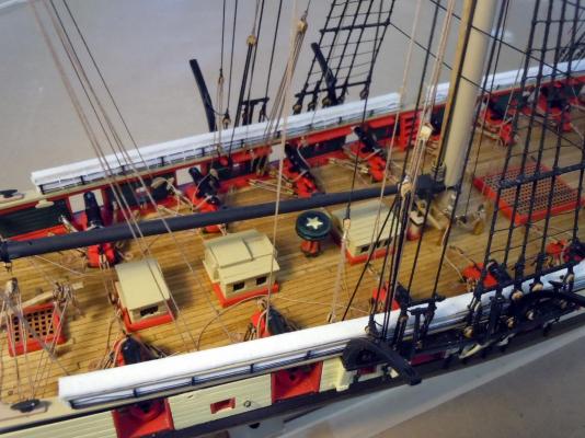
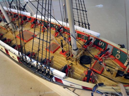
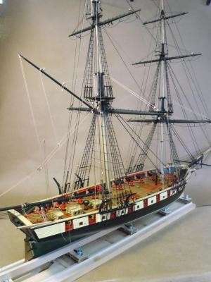
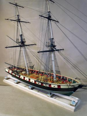
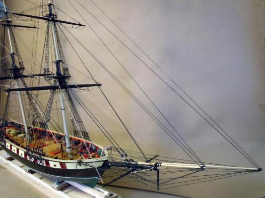
Here are pictures of the finished brig other than a couple of paint touch ups here and there. Being my first ship build I learned quite a few lessons that will certainly benefit future builds. I plan on building the USS Constitution and will do a little more research and study the plans before starting the build. I would also like to thank those that provided both guidance and encouragement during this build. Here are a random sampling of overall and detail pictures. Now to move on.


- 440 replies
-
- 22
-
-
- niagara
- model shipways
- (and 1 more)
-
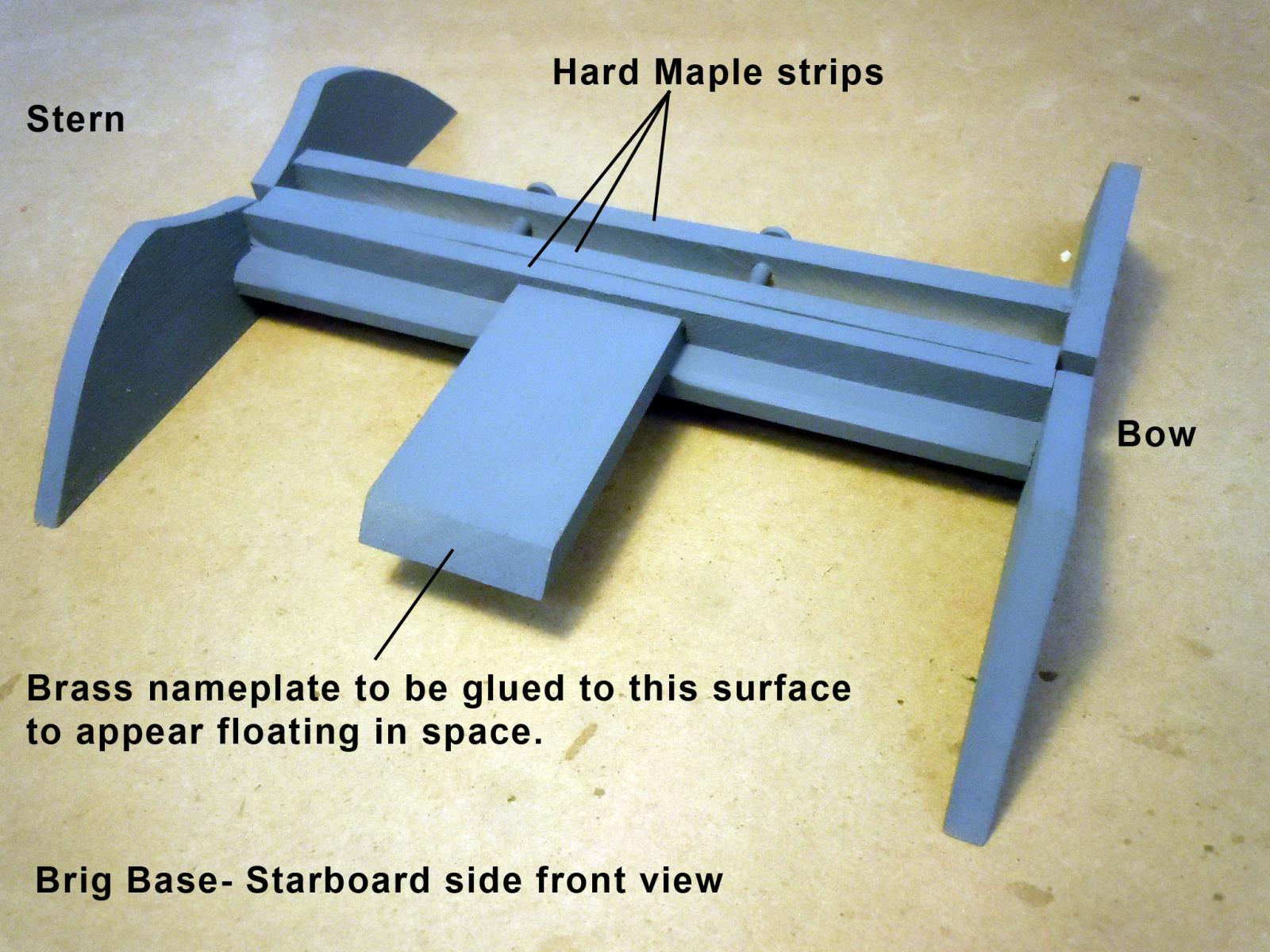
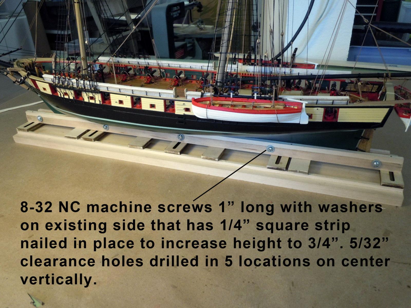
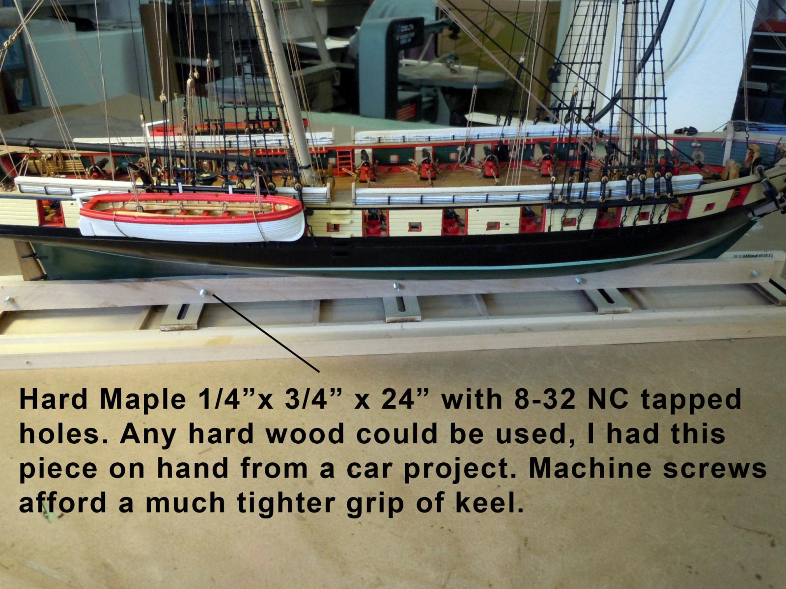
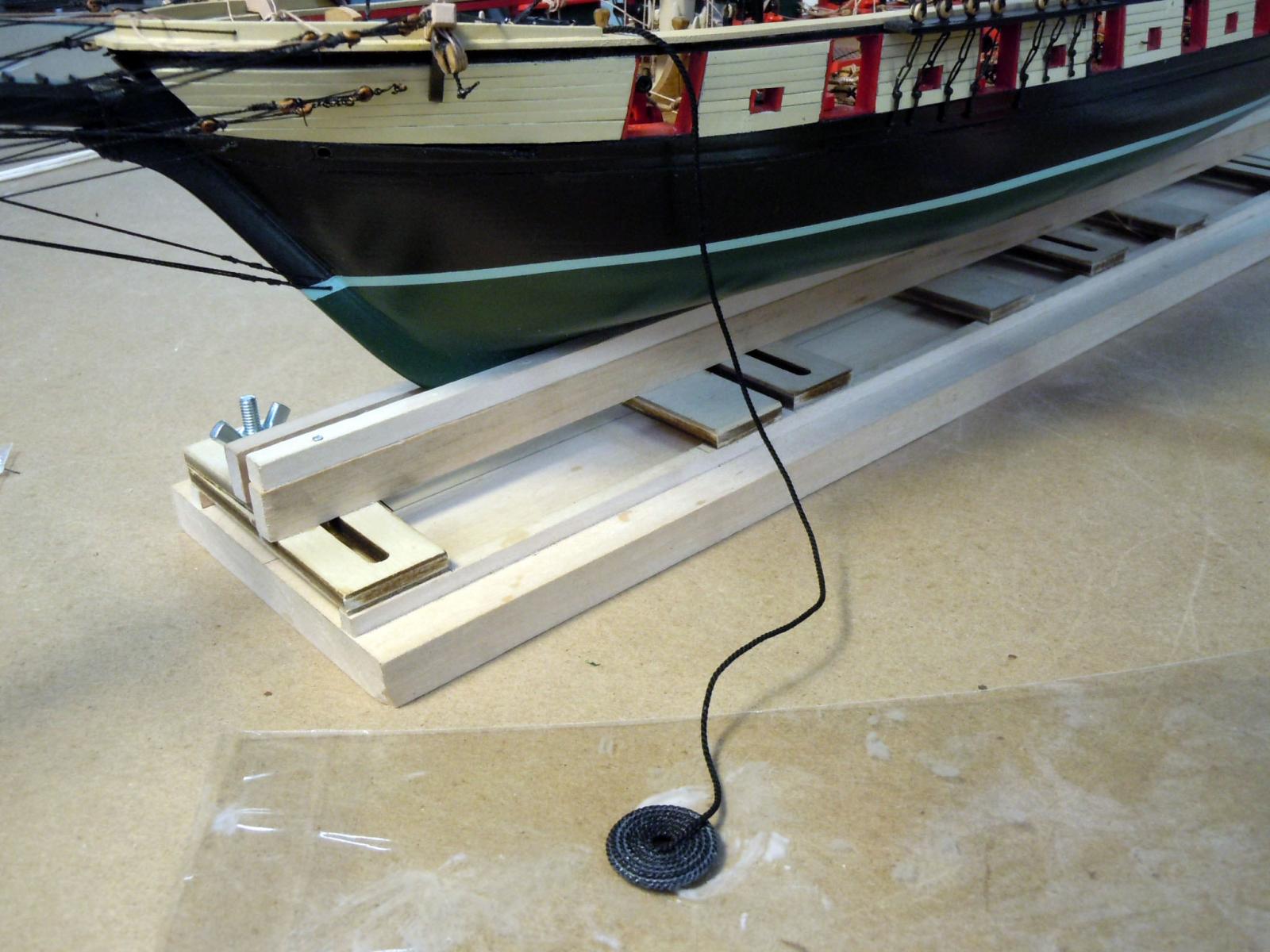
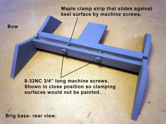
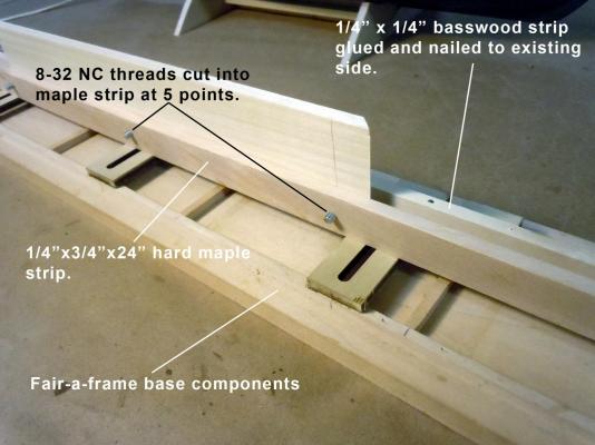
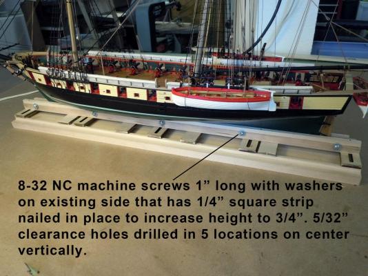
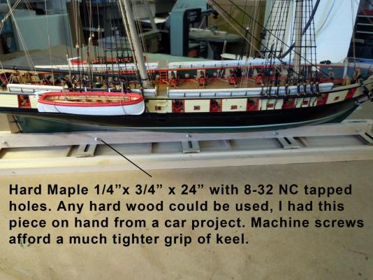
Designed up an earthquake resistant base since we live on the central coast of California that is more of a cradle design than the traditional pedestal type. I also added a location for a brass nameplate that I will have made. I photographed it in primer before painting black so the picture would be clearer to understand. I am using hard wood maple clamps with the rear side being tapped with 8-32NC threads for the clamp machine screws that will press against the keel. I am showing it in the closed position because I do not want the two clamping surfaces painted in the final base. I felt that paint on paint would over time bond together. I will paint it Satin Black to compliment the black on the brig. Here is the front view. The brass nameplate will be mounted on the angled surface. Here is the rear view with the machine screws. While working on the brig base I decided to modify the fair-a-frame working base to eliminate the wing nuts for a tighter clamp using machine screws with easier access. I used a strip of 1/4" x 3/4" x 24" as one side of the clamp that I drilled and tapped with 8-32NC threads on center vertically in 5 locations. I clamped the brig in place and it held much tighter than my first try with the wing nuts. This clamp will be put to good use on the next build, the USS Constitution. Here are the pictures showing it. My next post may be my last of the brig on the base completed with finished up images.

- 440 replies
-
- 13
-
-
- niagara
- model shipways
- (and 1 more)
-
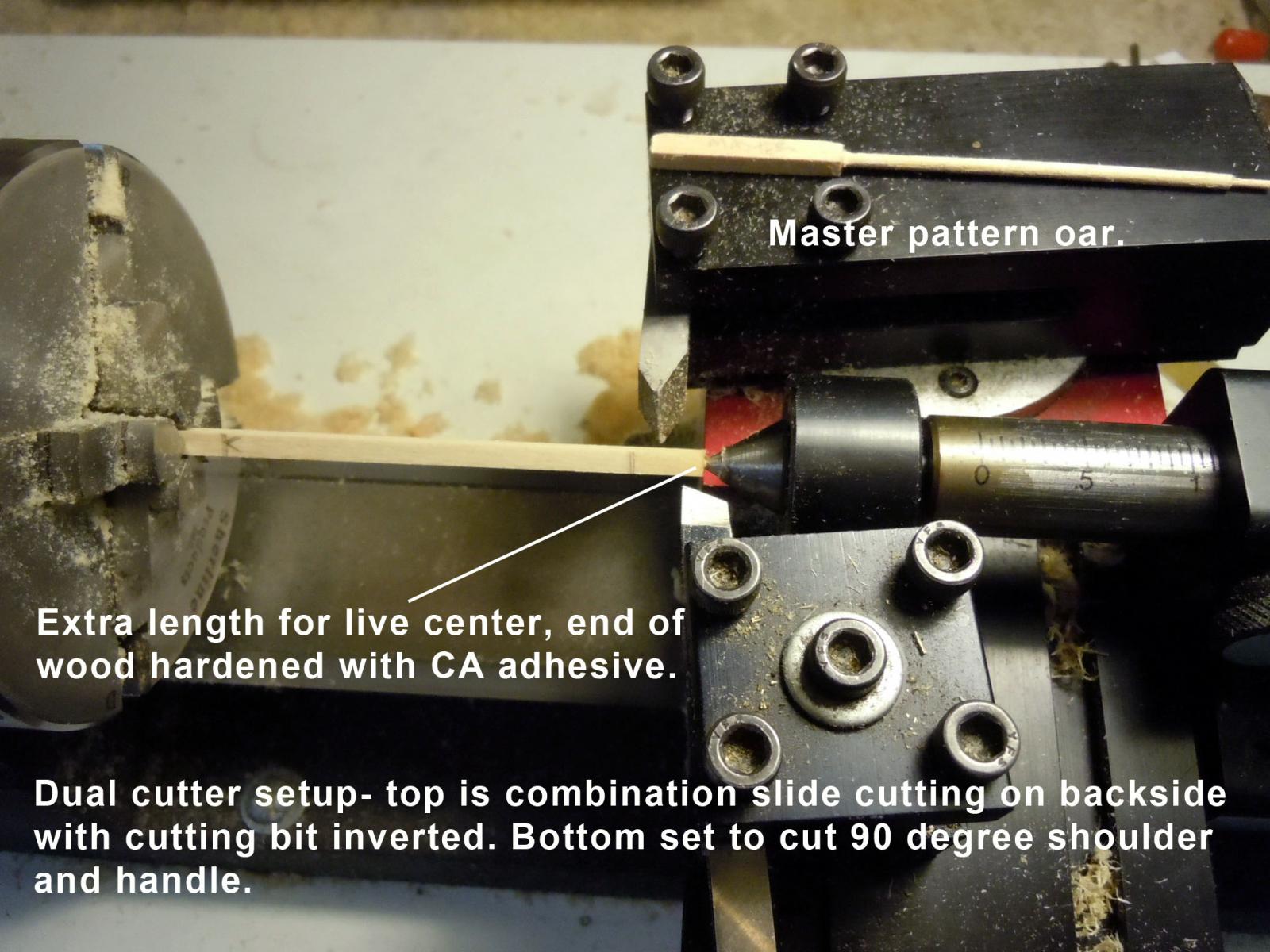
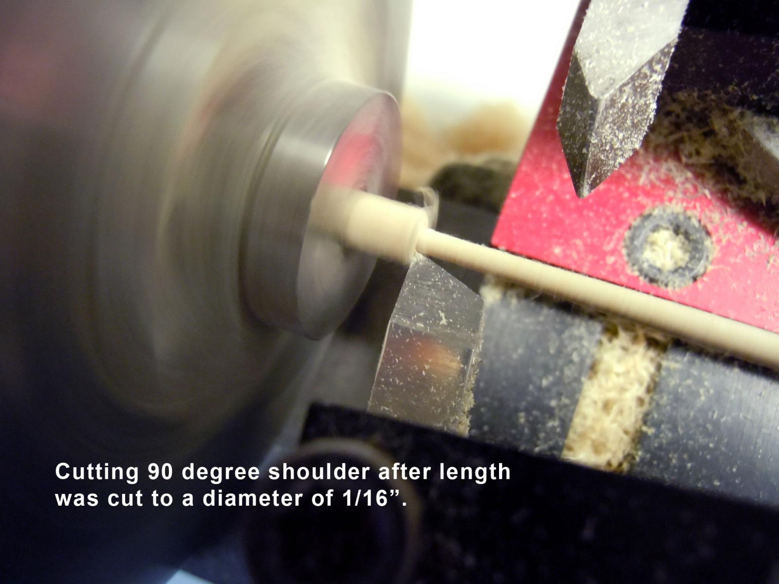
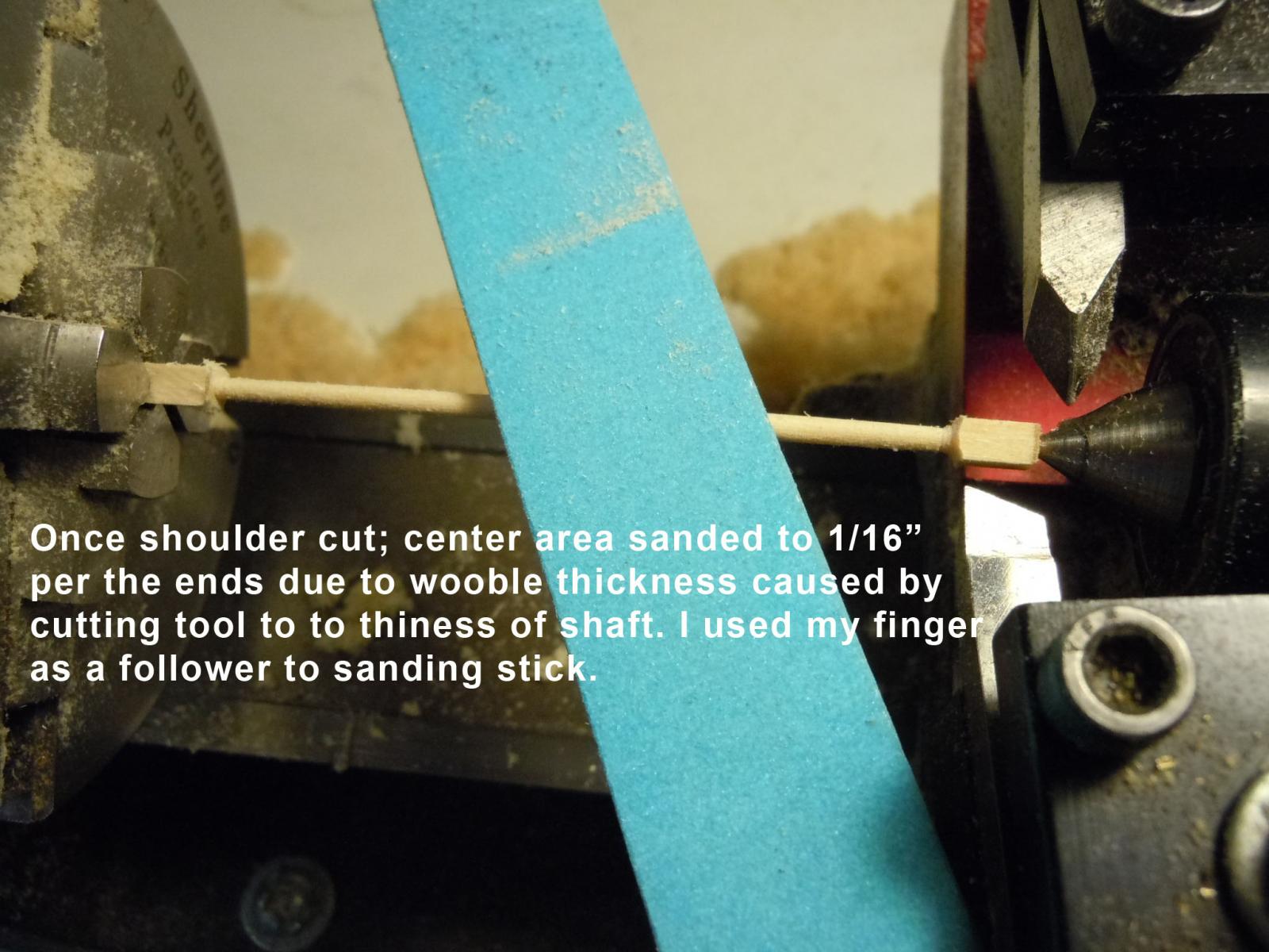
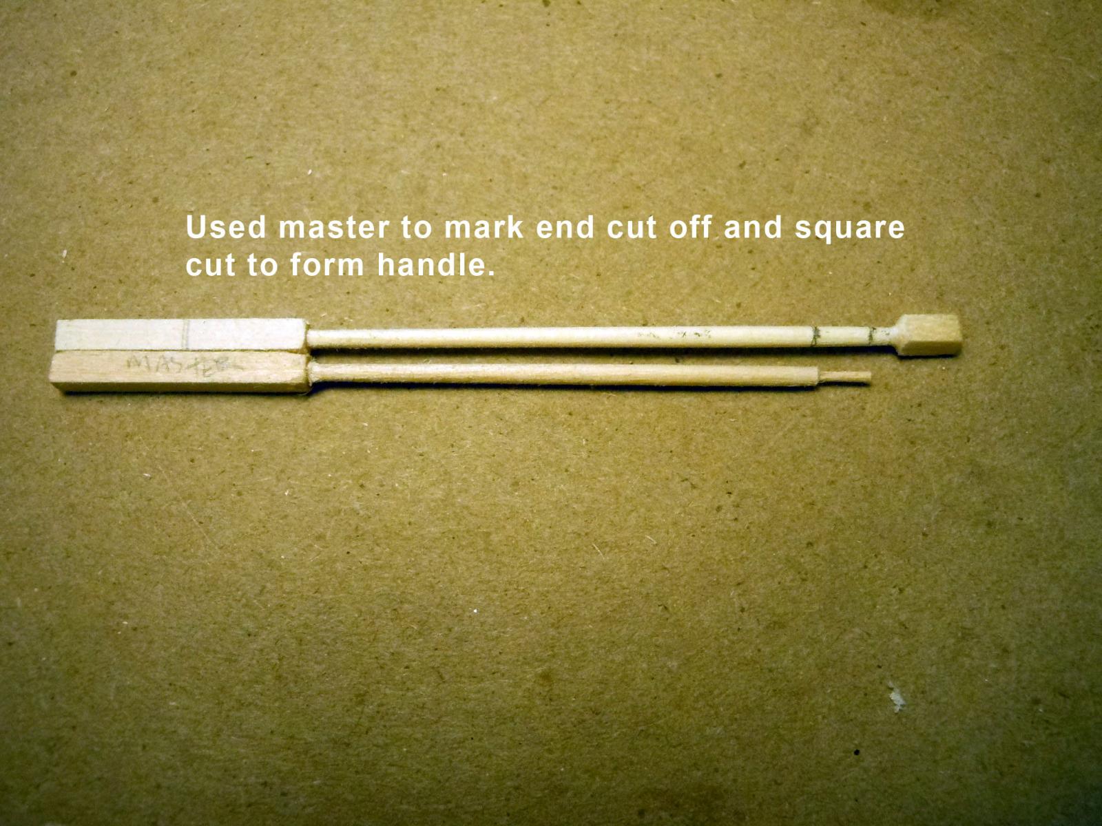
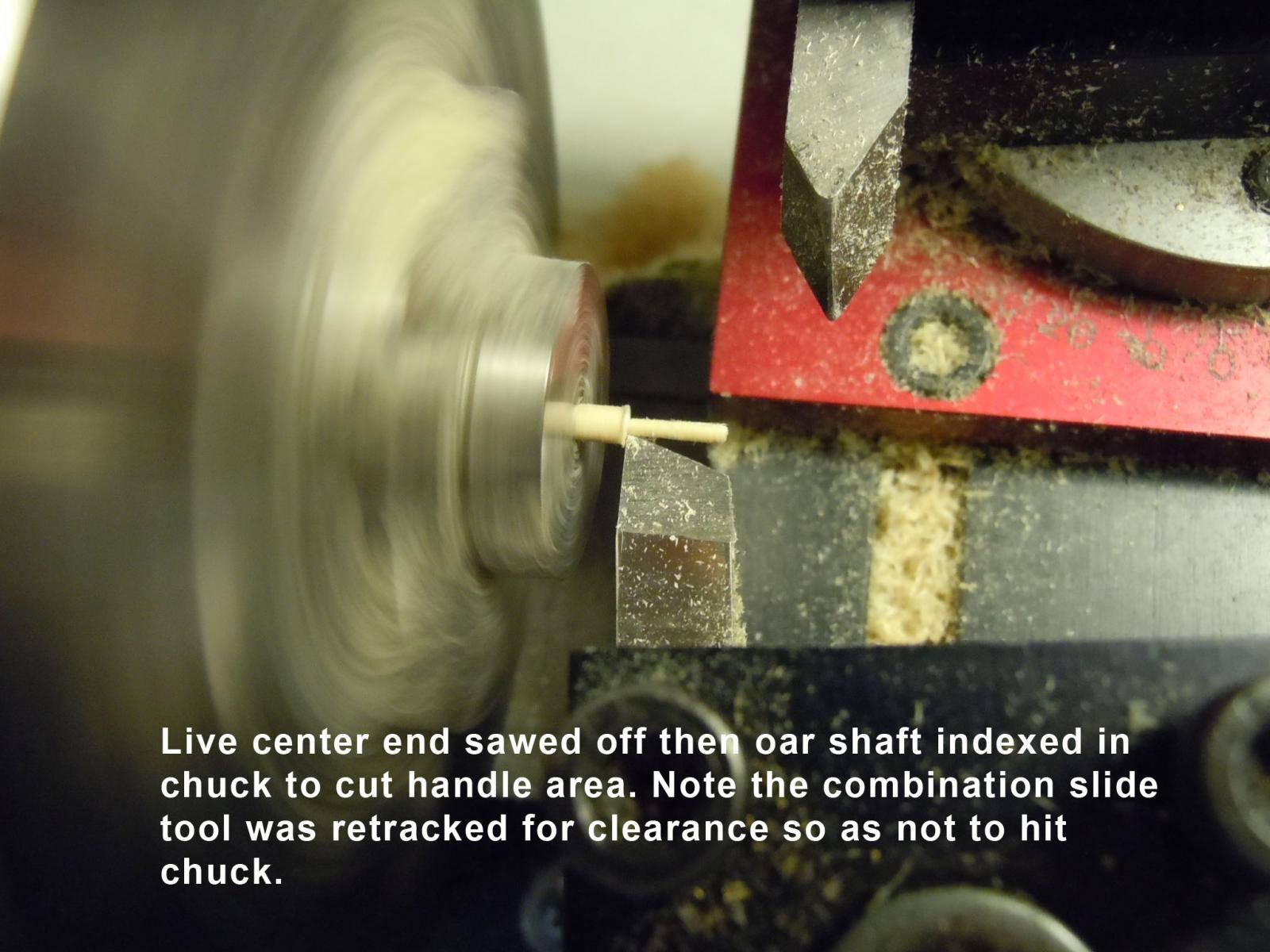
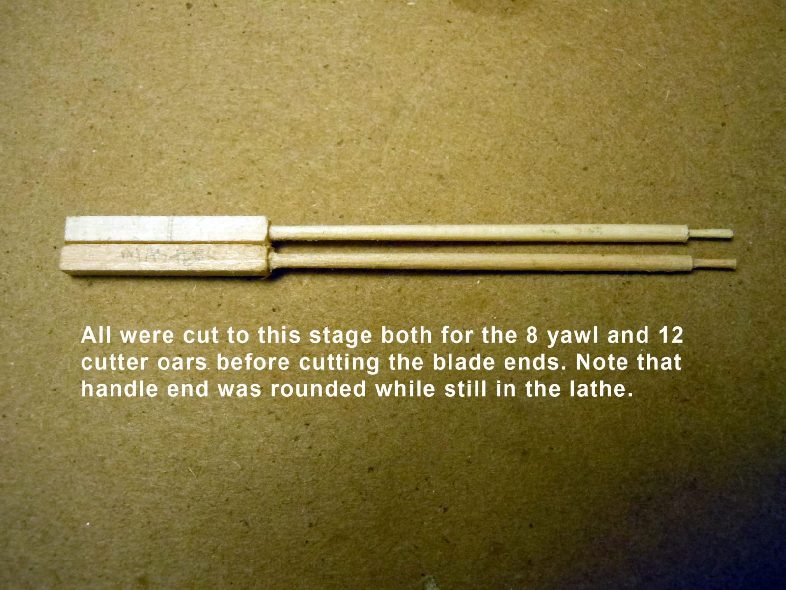
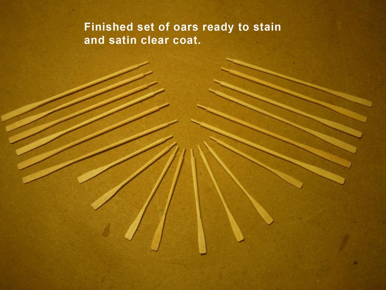
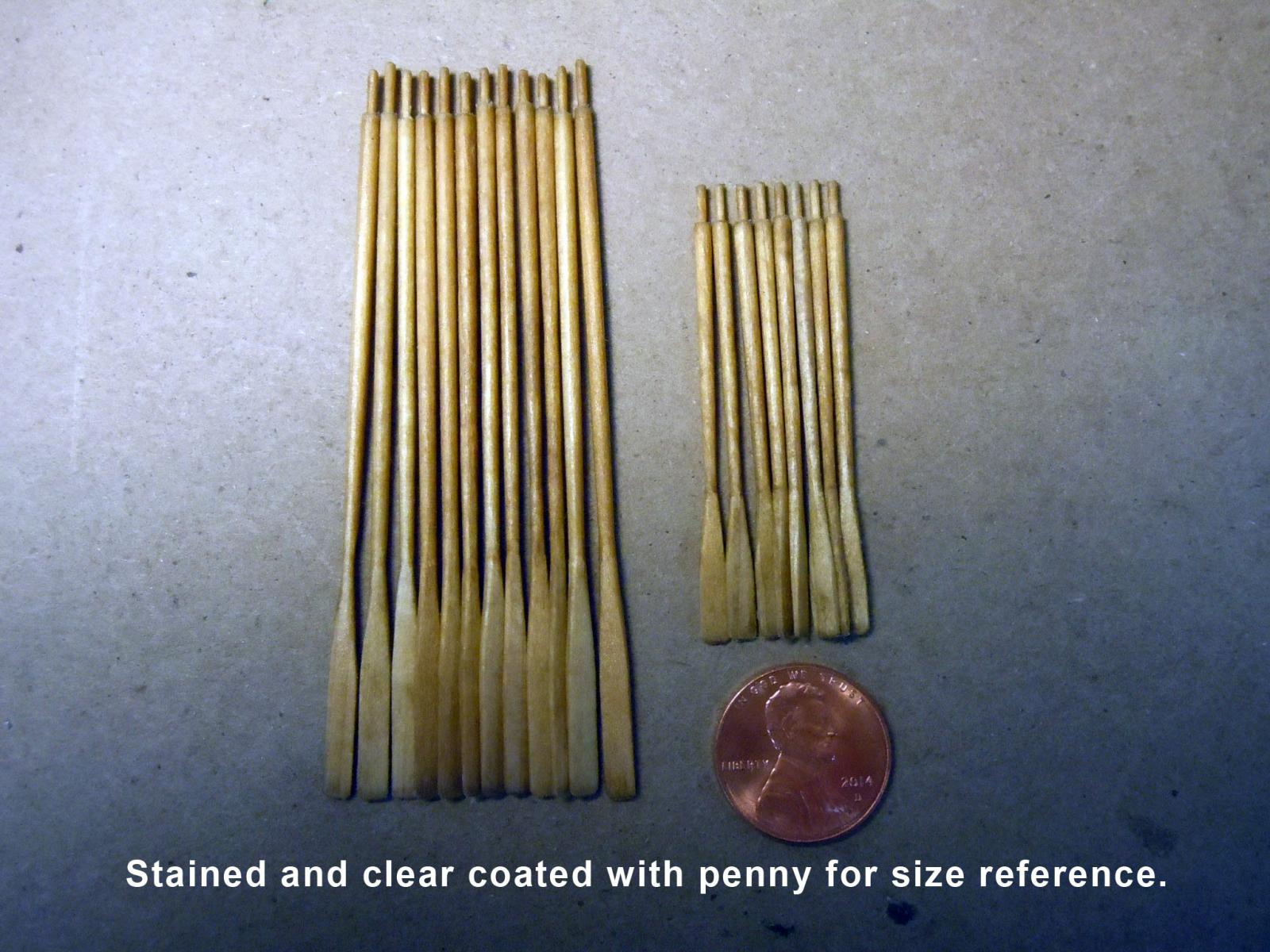
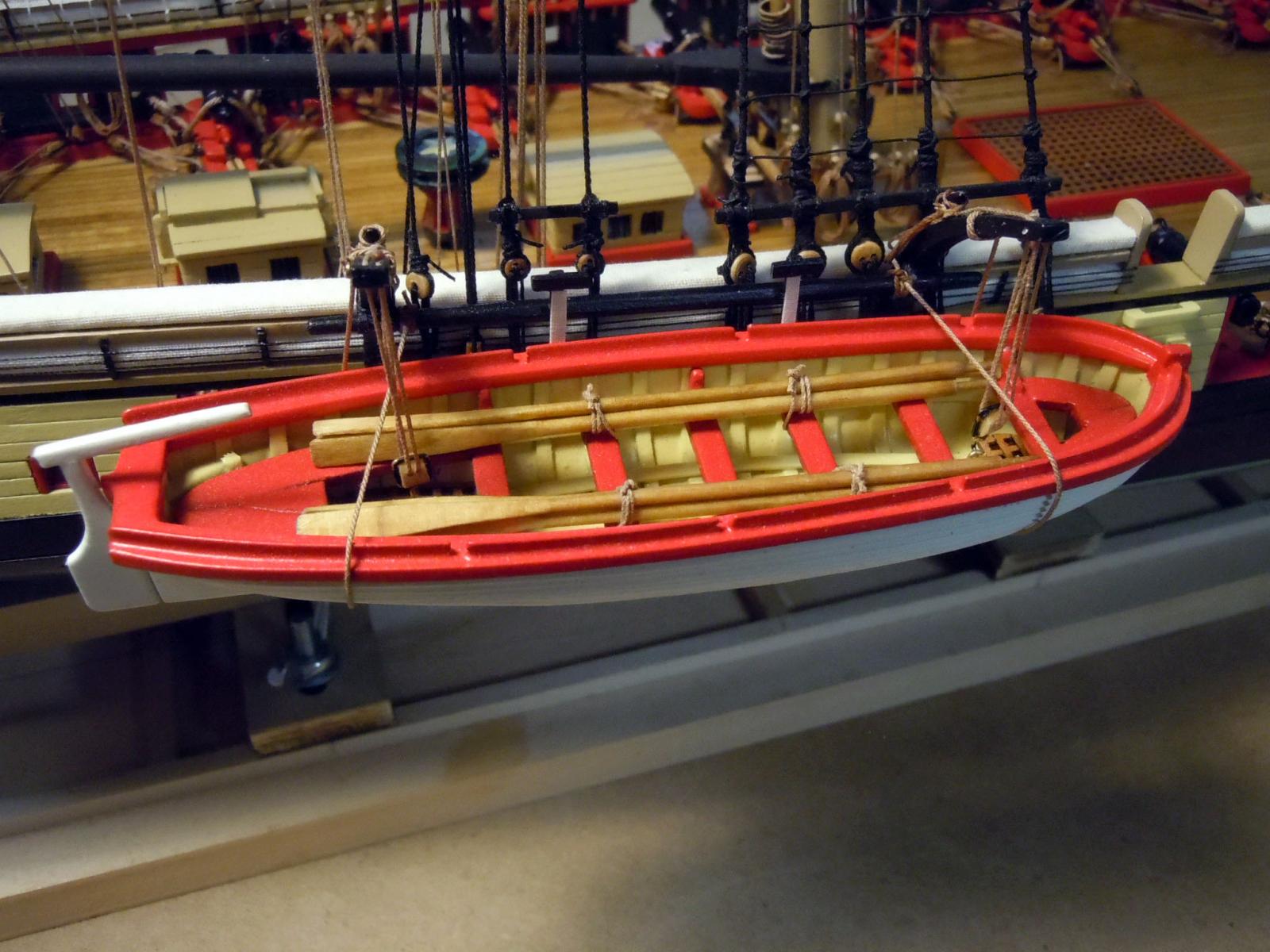
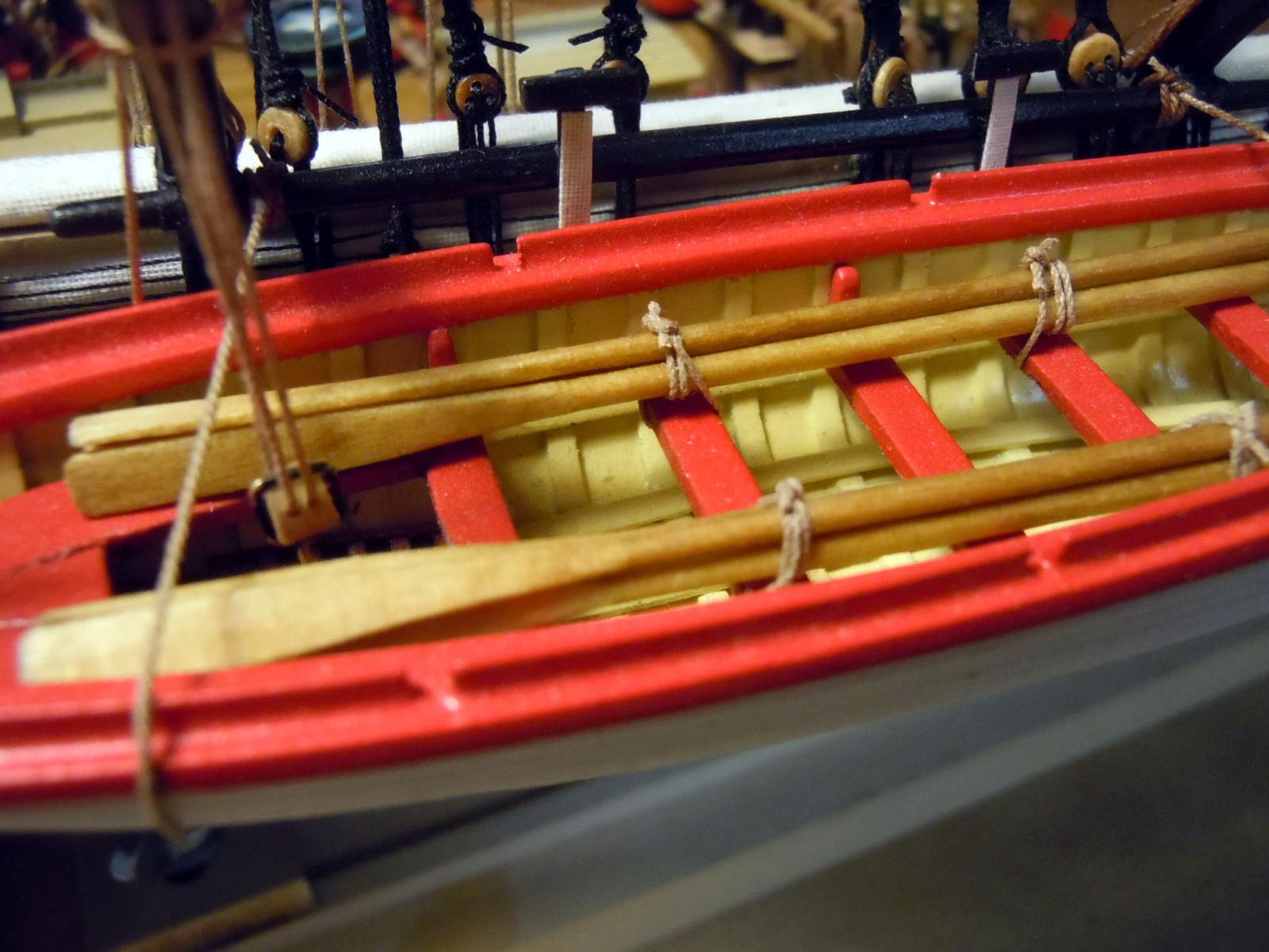
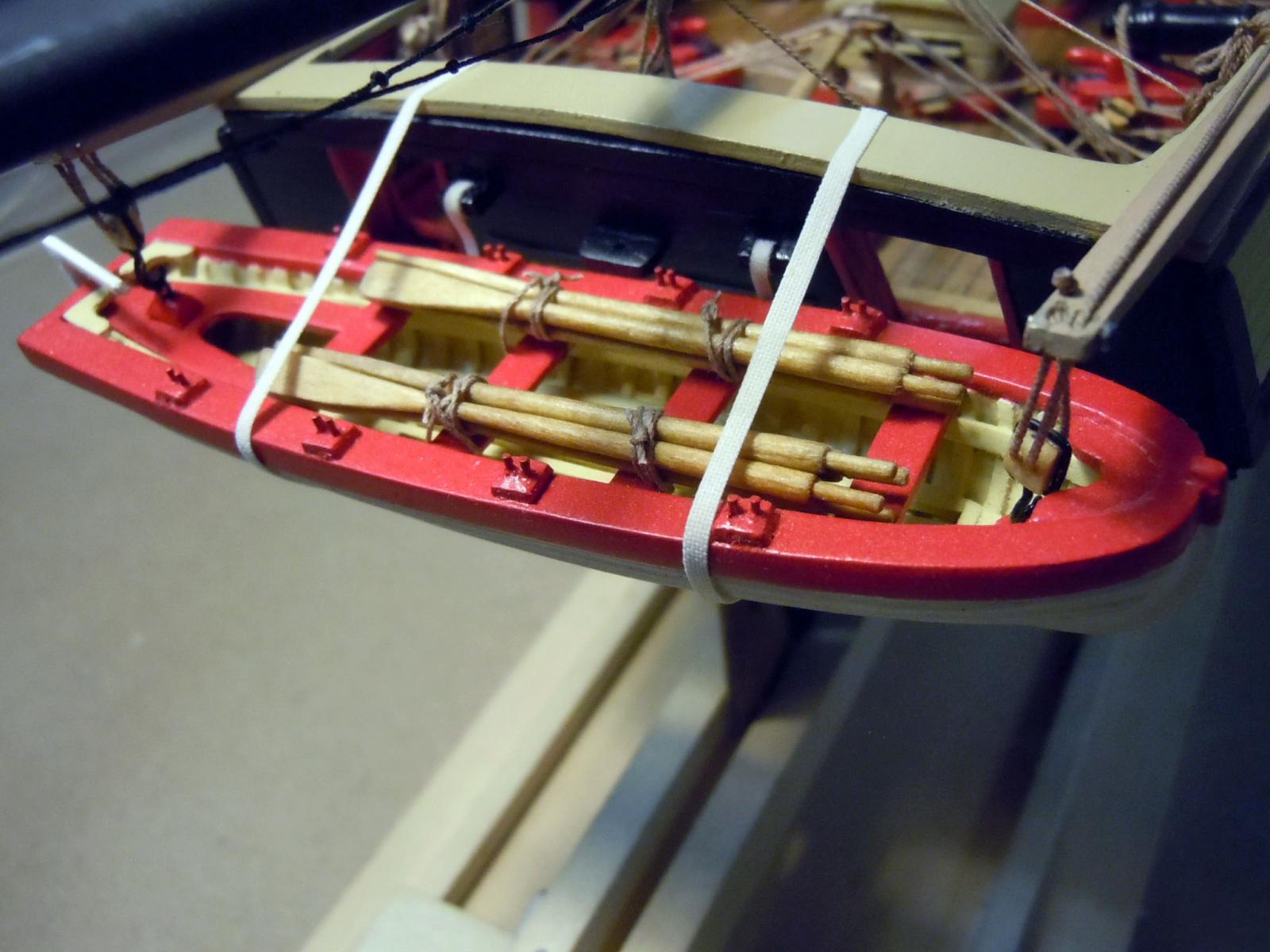
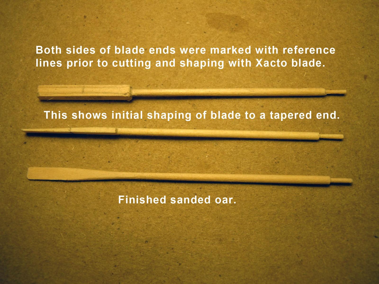
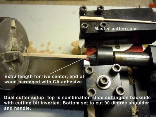
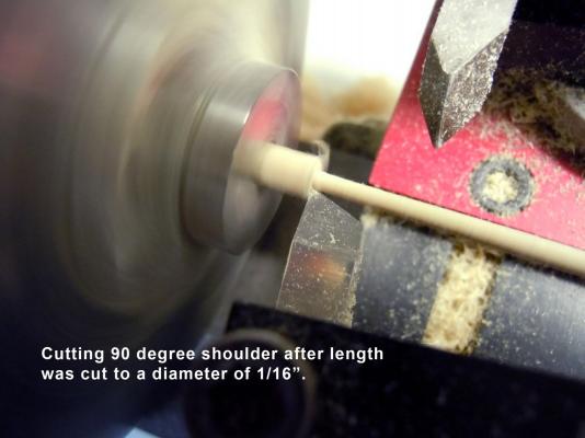
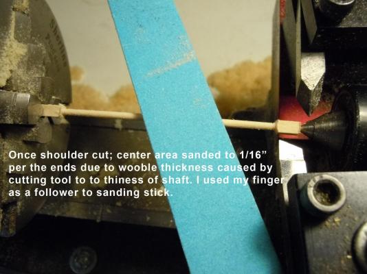
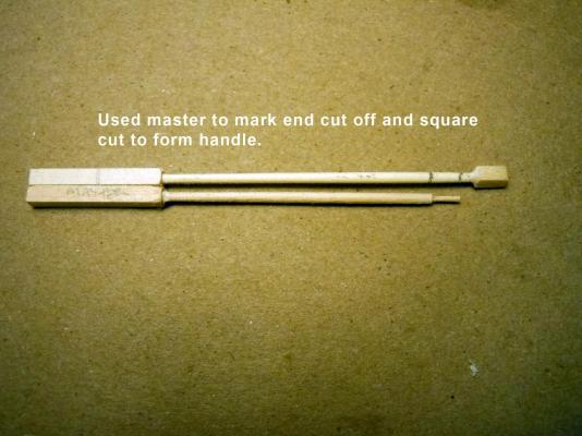
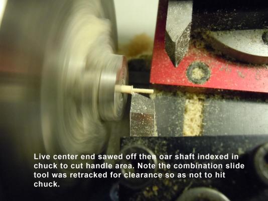
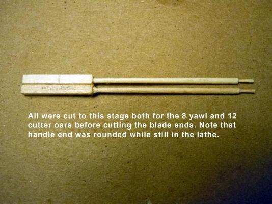
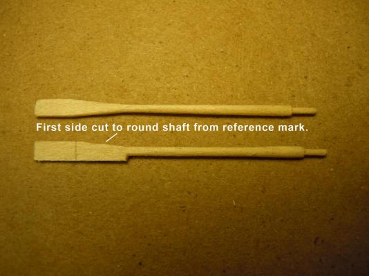
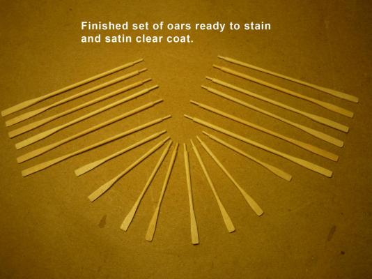
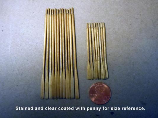
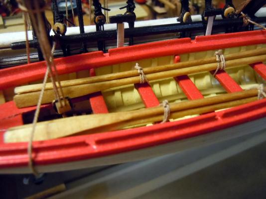
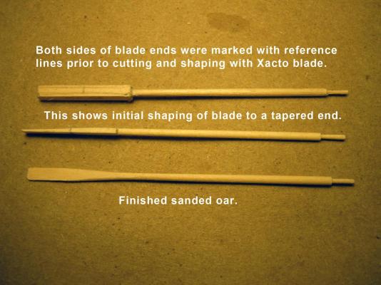
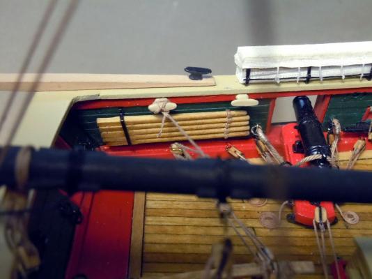
Spent a little time learning about oars; but could not find any details on how they were stowed in the boats so I used my judgement. Rather than one big bundle I split them into two bundles and lashed to the seats on either side of the tackle. I also documented the process I used to fabricate them for the benefit of other novices like myself. I used the 1/8" square basswood strips supplied in the kit. I would have preferred to use a harder wood like maple for lathe turning since the basswood was stringy and soft. Slow gouging, sanding and patience was needed. Also to help I hardened the live center end of the strip with CA to keep the live center in place. I setup my Sherline lathe to use the gouge cut on the backside and the front cut for the 90 degree shoulder for a reference point when cutting the blade. A picture is worth a thousand words so here are several showing the process from start to stowed. Now to finish up some minor details and build a temporary base.


- 440 replies
-
- 15
-
-
- niagara
- model shipways
- (and 1 more)
-
Brian, Great build! god is in the details and you have built great details. I love the base as well.
- 831 replies
-
- 7
-
-
- Armed Virginia Sloop
- Model Shipways
- (and 1 more)
-
Thanks for your kind words on this build! AvesP the clamp is the purchased Fair-a-frame from Model Expo and I added a strip to one side to work as a clamp. In the picture below it is the upper strip with the bar code; glued and nailed to the Fair-a-frame strip. This served me very well as I was able to turn horizontally flat on the antique drafting table that I use to build this and when an elevation angle was needed I used a rolled up towel under one end to position as needed. I am now going to turn oars for the small boats and start thinking of a base.
- 440 replies
-
- 9
-
-
- niagara
- model shipways
- (and 1 more)
-
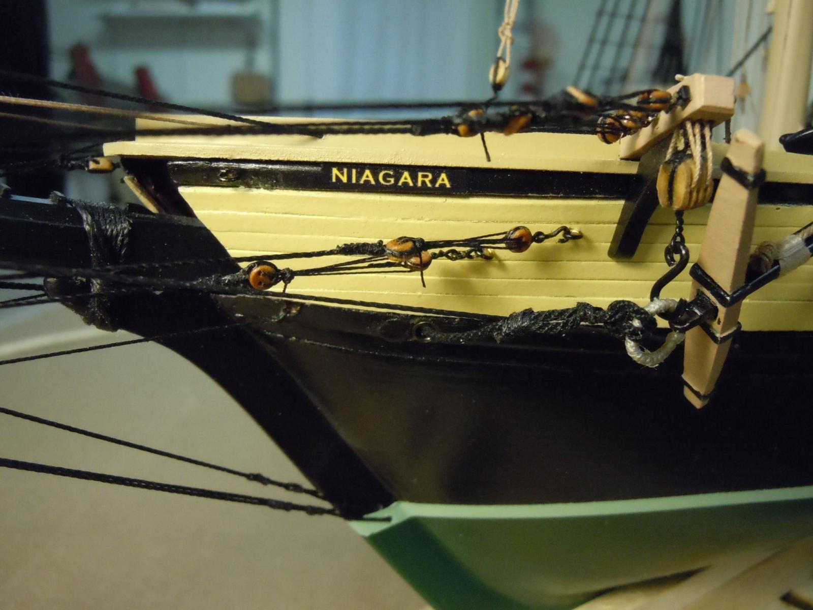
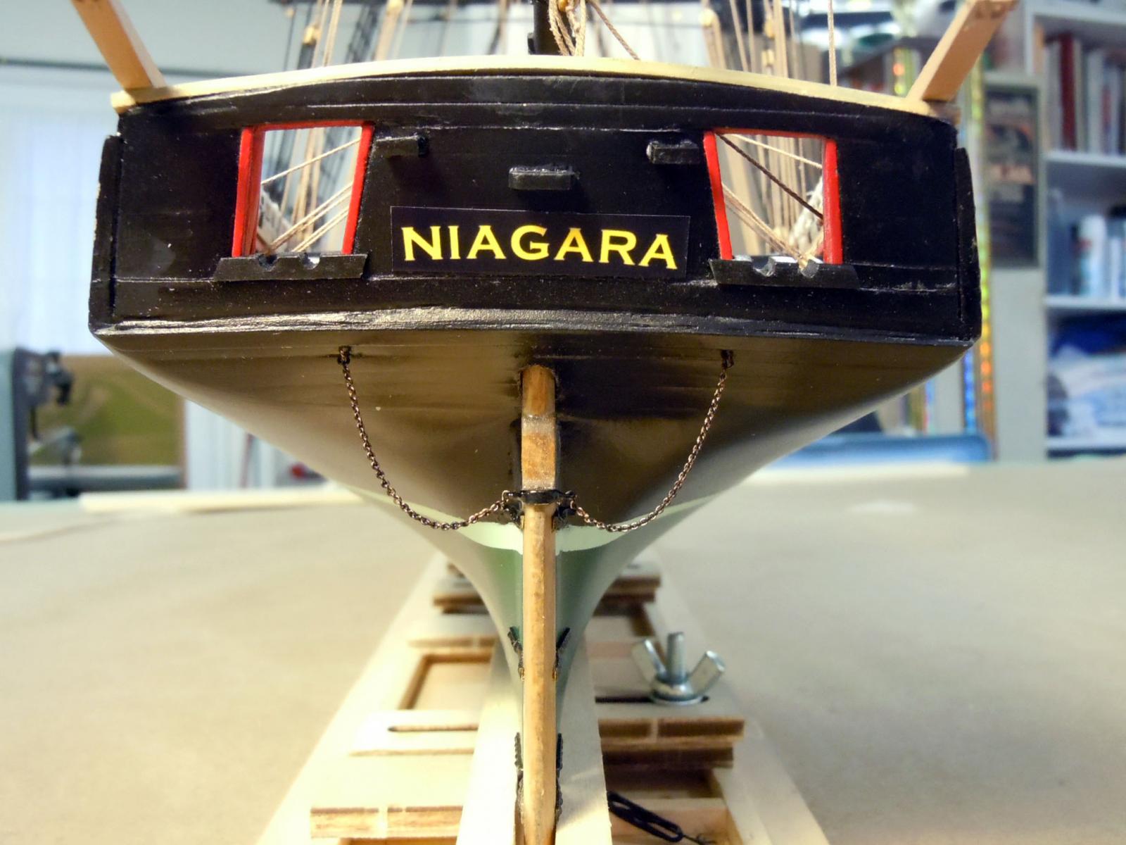
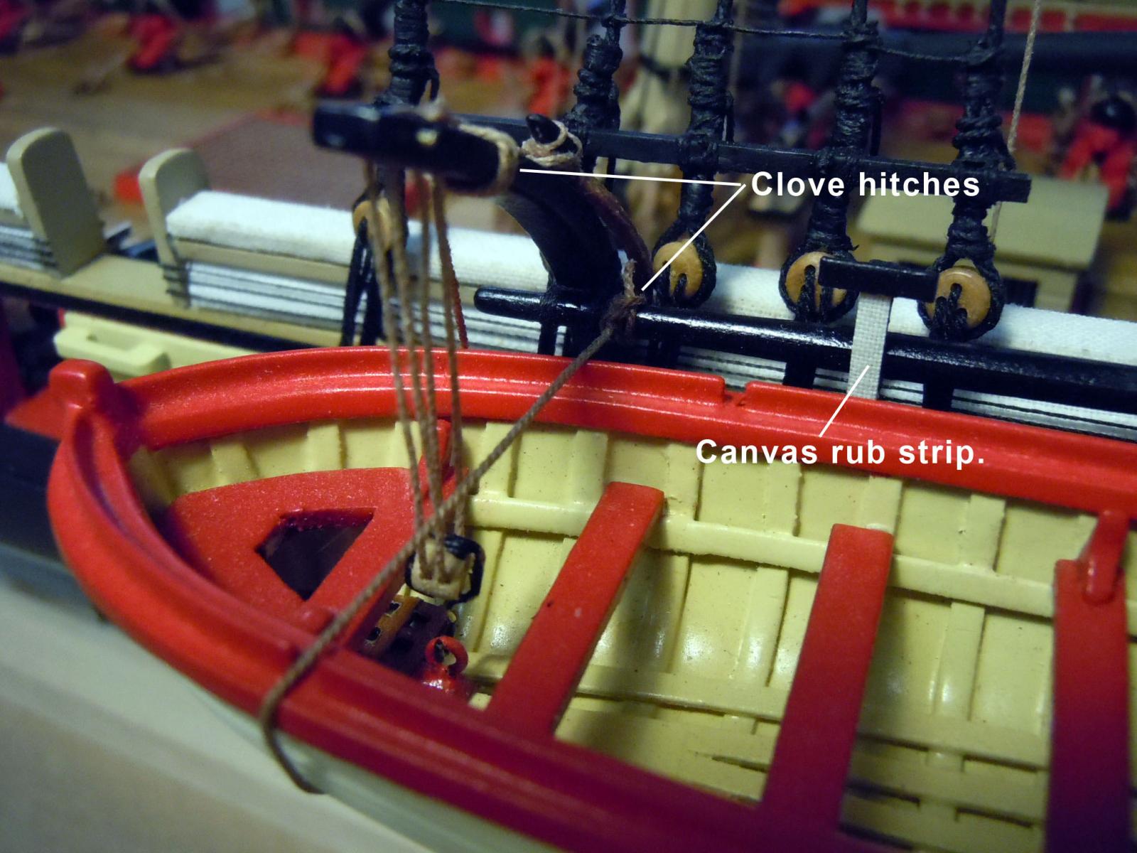
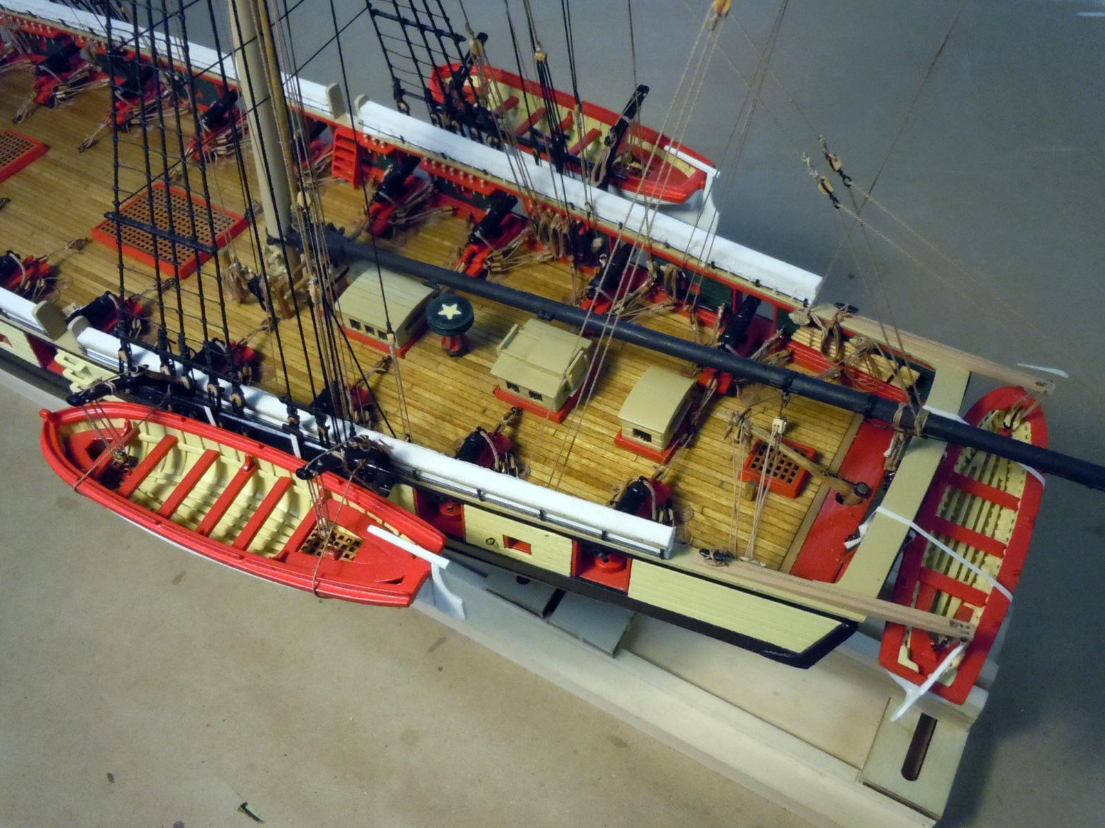
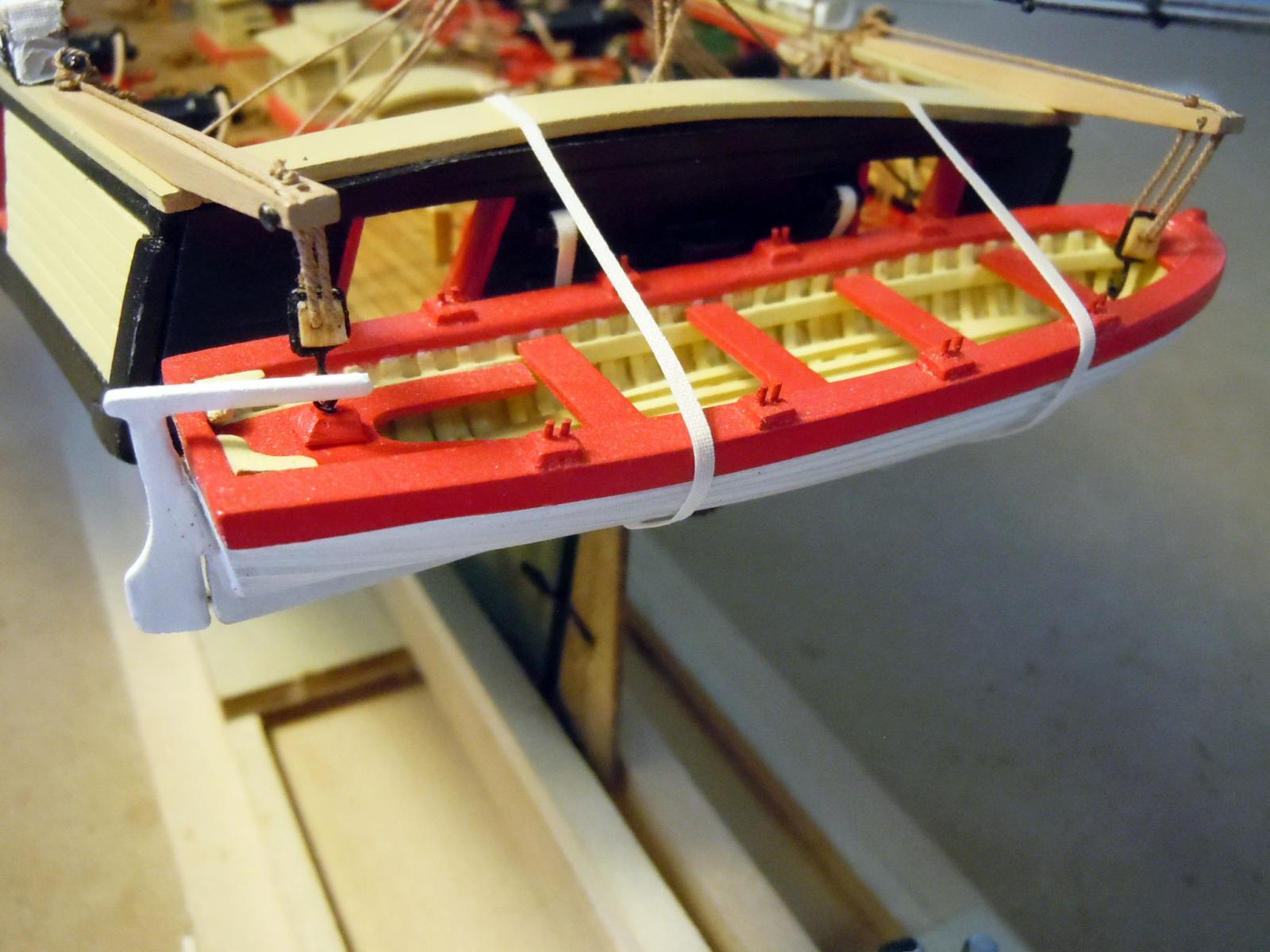
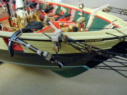
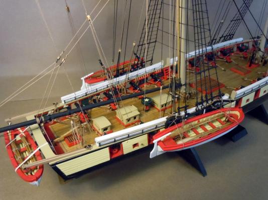
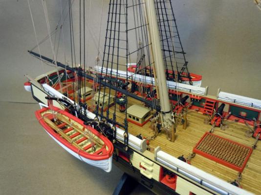
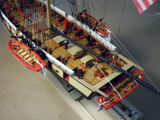
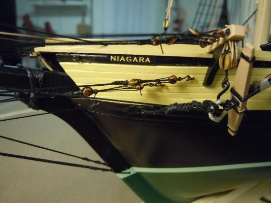
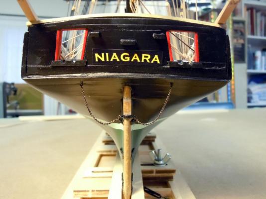
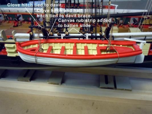
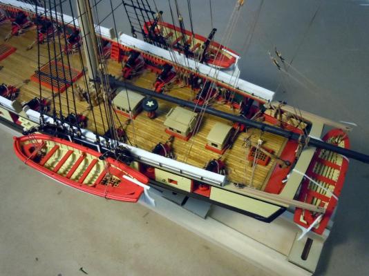
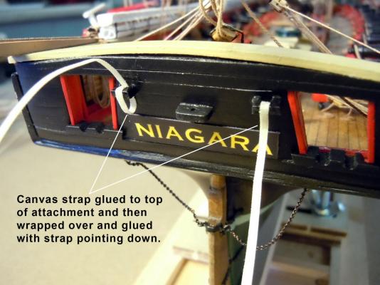
Here is the application of the Niagara name to the bow and the stern. The stern had to be added before rigging the yawl. This were printed using the artwork above on photo paper at 300dpi. Here is the port bow name. Here is the stern with a slight arc; keep in mind that once the yawl is added not much of this is seen. Here I am adding the canvas straps that hold the yawl. First I glued the end of the strip to the top surface and then wrapped it around and glued in place for an overlapping joint. The strips are white fine canvas sprayed with starch and ironed so it could be cut with a sharp blade for a 1/16" strip. The strips were then wrapped around the yawl and up and over the rail and attached the the upper ring on the stern bulwark. To tie the knot to the ring re-wet the strip to make it pliable and easy to tie. Next came the two cutters. First I add the canvas rub strips to the wooden slide battens. Then I tied .018" rope to the davits using a clove hitch half way between the cleat and the end sheave. Wrapped the ropes around the cutters while suspended in place and tied a clove hitch to the round section of the davit brace and cinched up to hold the cutter parallel to the water level. Here is a close up showing better detail. This shows an overview of all in place. Now to make up the oars for them and any other details like the 20 sweeps which are mentioned on the plans, but no information on where they were stowed. Ideas on where they ought to be stowed would be appreciated, or if they need to be added at all.

- 440 replies
-
- 14
-
-
- niagara
- model shipways
- (and 1 more)
-
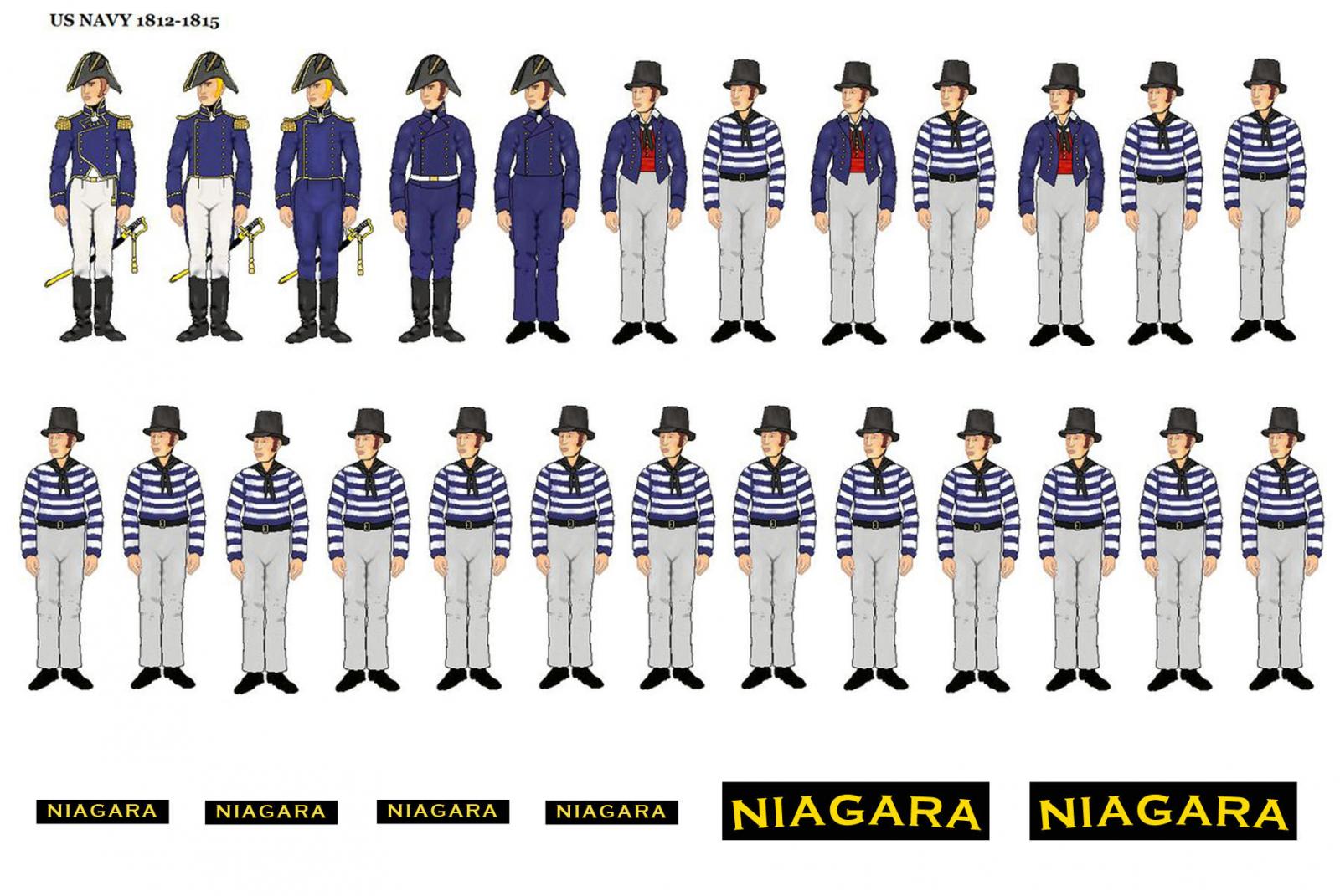
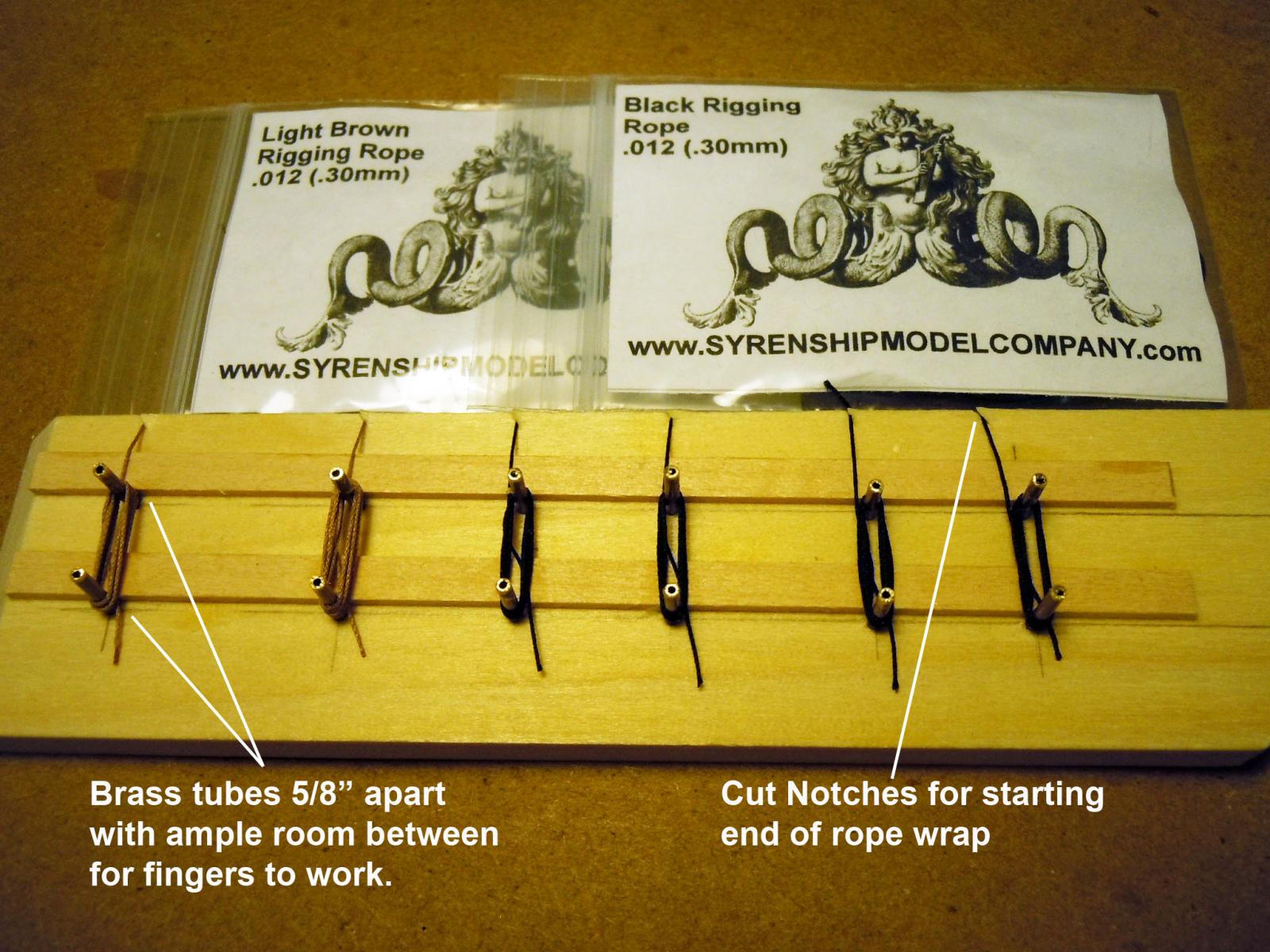
Just finished up the rope coils at all the attachment points this was a tedious time consuming process getting them all to hang the way gravity should have them hang versus how they wanted to hang. I went through a quick learning curve. The last of them are drying. I did some research on the sail making and a couple of seasoned pros recommended that sails should be added to the yards before the yards are added to the masts. Trying afterward they will never look correct regardless of the multitude of rope lines to work through. I will save the sails for the Constitution. I then turned my attention to the cutters and yawl and quickly realized it was time to add the name. I recreated the name artwork for the bow and stern with the stern location having a slight arc. Please feel free to copy for personal use; no resale. I also created a correct size basic crew in picture form from the captain on down to crewman. This was so my wife could understand the relative size of the brig to people. Does anyone know of a source for this size of 3D cast period naval figures? Here is a 4" x 6" image that I printed out on photo paper that will work well for what I wish to do.
- 440 replies
-
- 9
-
-
- niagara
- model shipways
- (and 1 more)
-
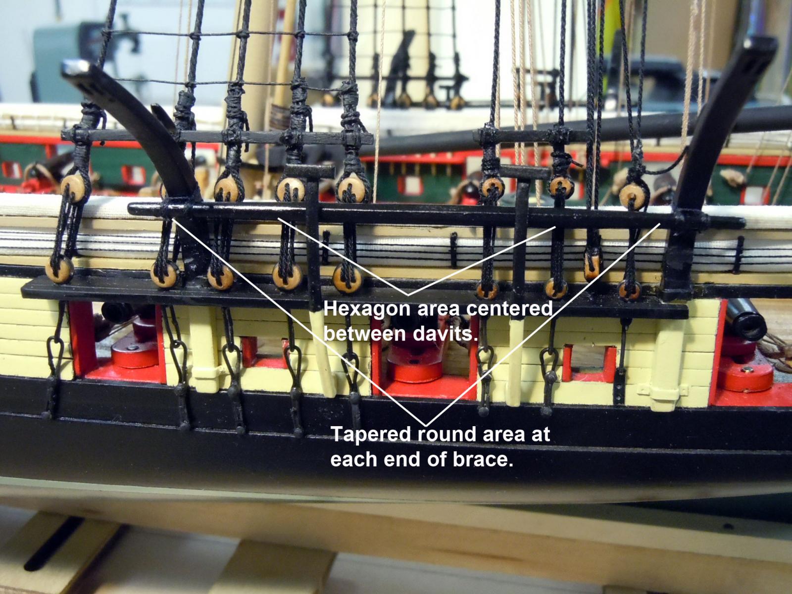
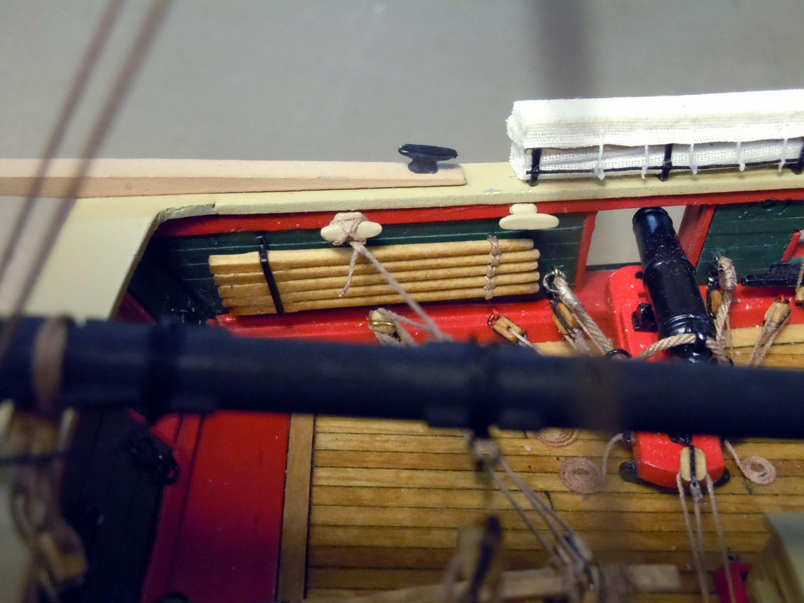
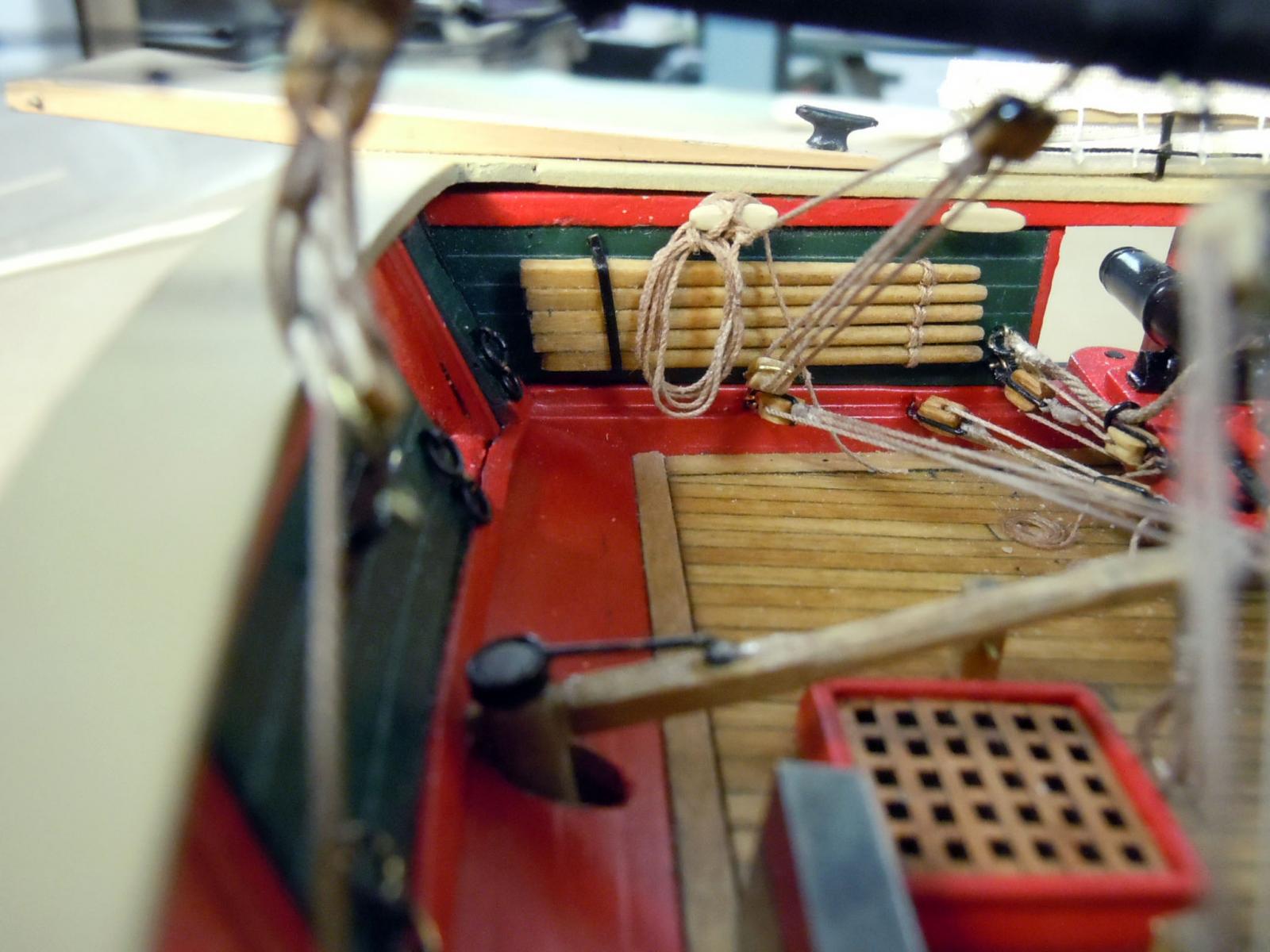
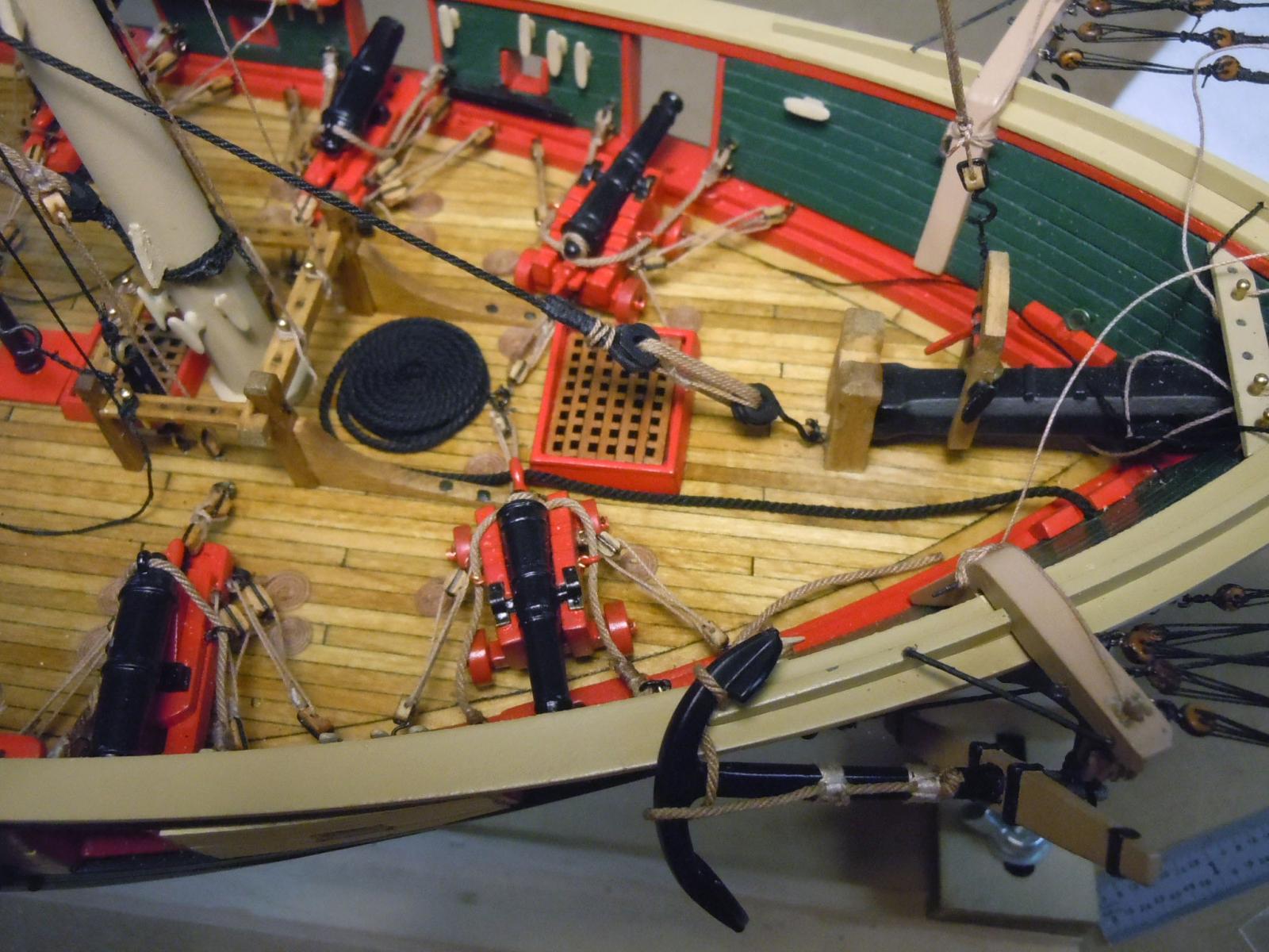
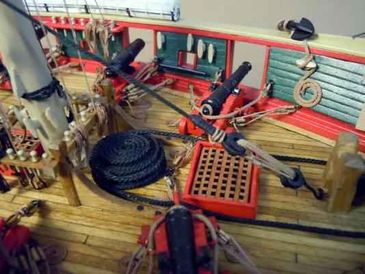
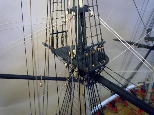
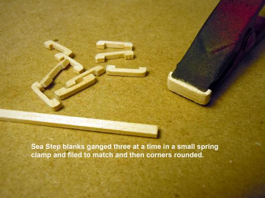
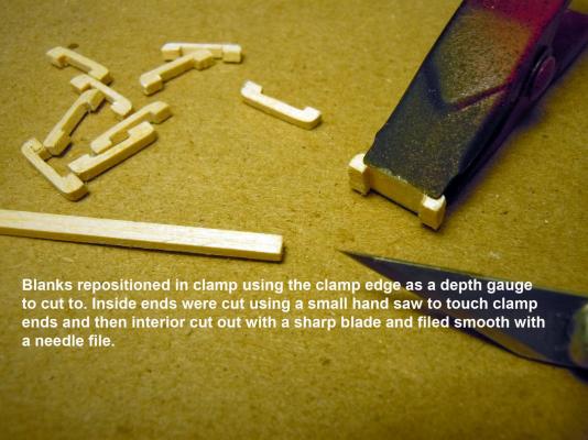
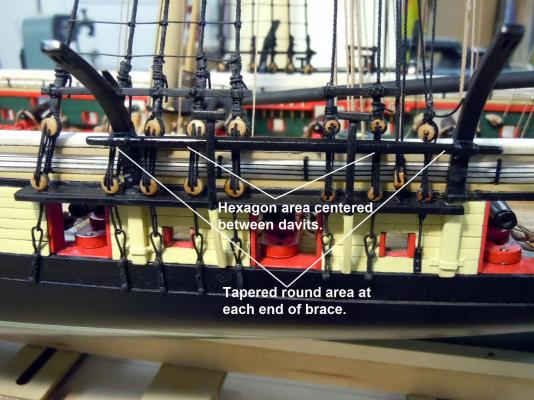
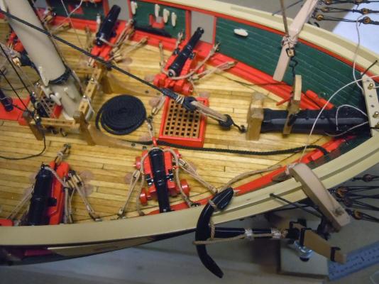
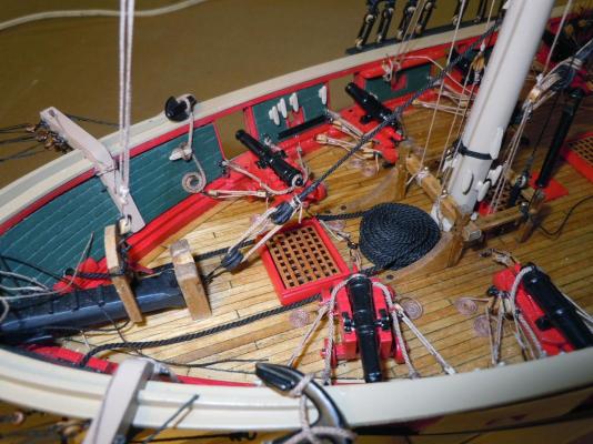
Started working on details that were either overlooked or needed to be done looking at both the plans and the replica brig pictures. Here is how I made the sea steps based upon the pictures of the replica. 12 were needed so I cut the 1/16" x 1/2" blanks and worked on three at a time while ganged in a small spring clamp. They were then primed and painted both the yellow and black and glued in place. I turned two davit braces with the center area a hexagon while the ends were turned round tapers. They were glued to the davits and then tied with black thread. Next I addressed the capstan bars starting with 1/16" square basswood strips 1-1/4" long. The square was marked off at 5/16" and indexed into the four jaw lathe chuck and the taper filed using a sanding stick and my left middle finger as a follower while sanding. !0 wee needed. The bars were stained and clear coated and two sets of 5 glued at an angle. The brass strips were formed, painted and glued to the oar sets. The tapered ends were tied together using brown .008" rope. Each set was then glued to the wall. Here is a fixture I made to form the coiled ropes that hang on various belaying pins. This is were I am presently at making the rope coils. Once wrapped around the brass tubes they were painted with the 50/50 white glue and water mixture and allowed to dry. The two strips keep the coils elevated to facilitate removal. When dry and removed I then soaked the dried coil in water to wet and then formed for each position with a dab of 50/50 mixture at the pin to hold in place. If you get too wet touch the coil with a Q-tip to weep excess water off. I varied the number of rope wraps from 3 - 6 for variety based upon the down rope position. Now back to finishing up the rope coils. I am toying with adding sails which I think I would have to done before adding the life boats to make it easier.


- 440 replies
-
- 14
-
-
- niagara
- model shipways
- (and 1 more)
-
Just a friendly tip about laser cut parts. The burning process creates a slight angle and the thicker the wood being cut the greater the angle. I mark parts with a pencil line before cutting front the parent sheet so I know which side is front so when adding the bulkheads I can position forward bulkheads one way and the rearward the opposite. Sand the edges and put on a flat surface and set a square to see the difference. Just FYI.
-
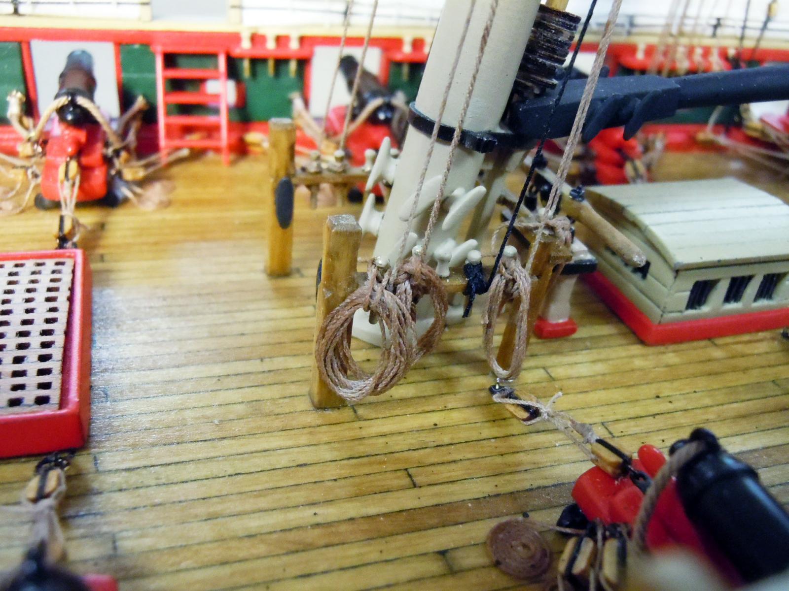
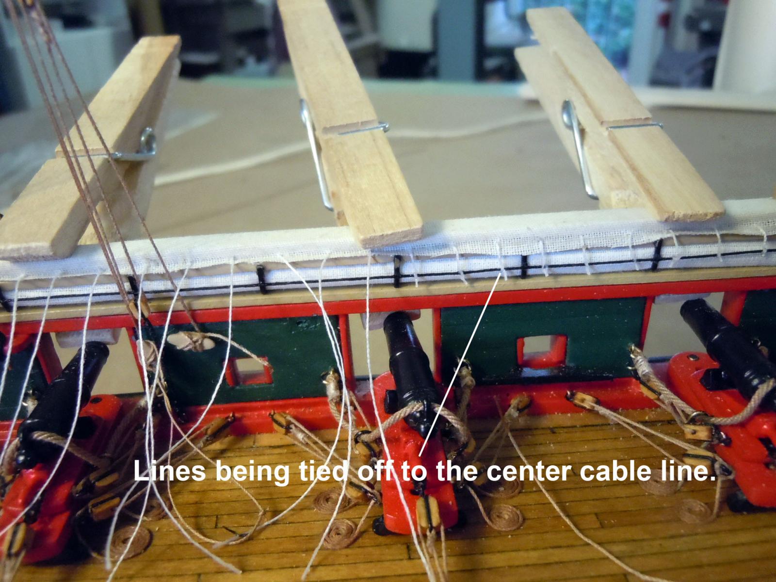
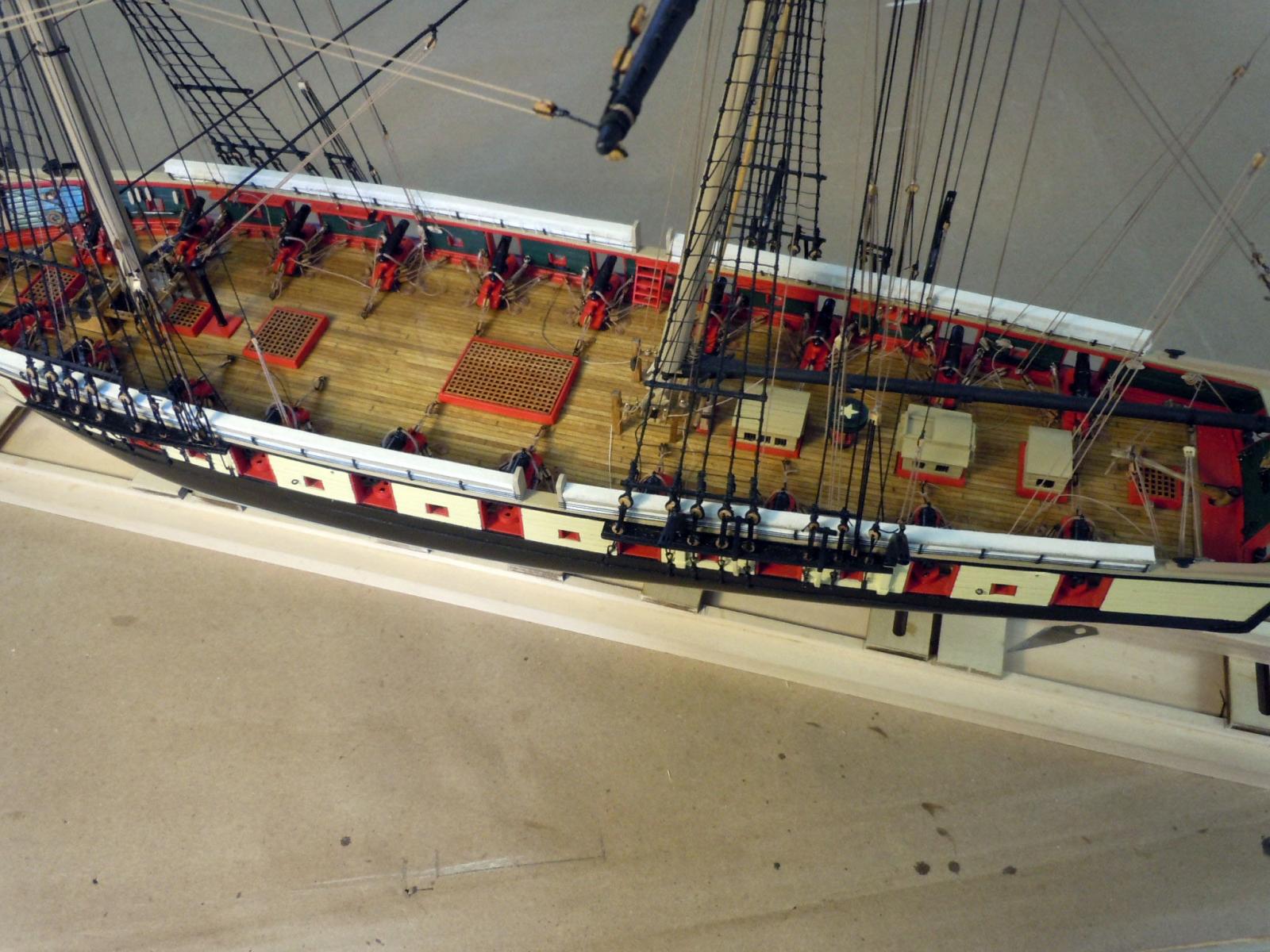
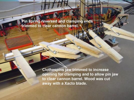
I finally finished up the hammock covers; again to reinforce the making of these would have been much easier without the masts and rigging lines in place. I was able to maintain my sanity while further developing my patience, ambidexterity, depth perception and knot tying with tweezers. The caps were edge formed using 1/4" x 1/16" thick strips curved to match the rails. They then were painted white since the fabric was slightly transparent. Once dry each was covered in fabric glued on the bottom side wrapped over the top and down the other side and allowed to dry. The fabric standing edge was treated with 50/50 glue/water mixture to stiffen. Pencil marks on the bottom side indicated where holes were drilled in the standing edge using the .020" drill bit. Then thread was inserted into the hole and glued to the bottom side. After all the holes were drilled the standing edge was then cut down to 1/8" off the wood strip. Once all the threads were in place and glue dry the cover was indexed to the rail making sure all the thread lines are clear and glued in place using white glue and modified clothespins as clamps. The tips of the clothespins need to clear the cannon; and reduces the clamping force so as not to crush the rail system. When the glue was set on the cover to the rail then the fun began tying lines to the inside center cable. I found it easier to glue the knots by adding CA just below the knot and let it weep into the knot and this also provided a stiff line to cut off with small sharp at the tip scissors. I was able to carefully navigate all the rigging lines to tie the knots to the cable. This is where the patience and other skills came into play and you can see why this would be much easier to do without the masts and rigging in the way. Here are some views of the finished covers. Next I will start cleaning up the belaying pin attachment points of all the rigging lines now that they have had time to stretch and relax. Make oars and other details.

- 440 replies
-
- 13
-
-
- niagara
- model shipways
- (and 1 more)
-
Very nice coils I will have to check back when I get to do them for the Brig. Great work and keep it up!
- 831 replies
-
- 4
-
-
- Armed Virginia Sloop
- Model Shipways
- (and 1 more)
-
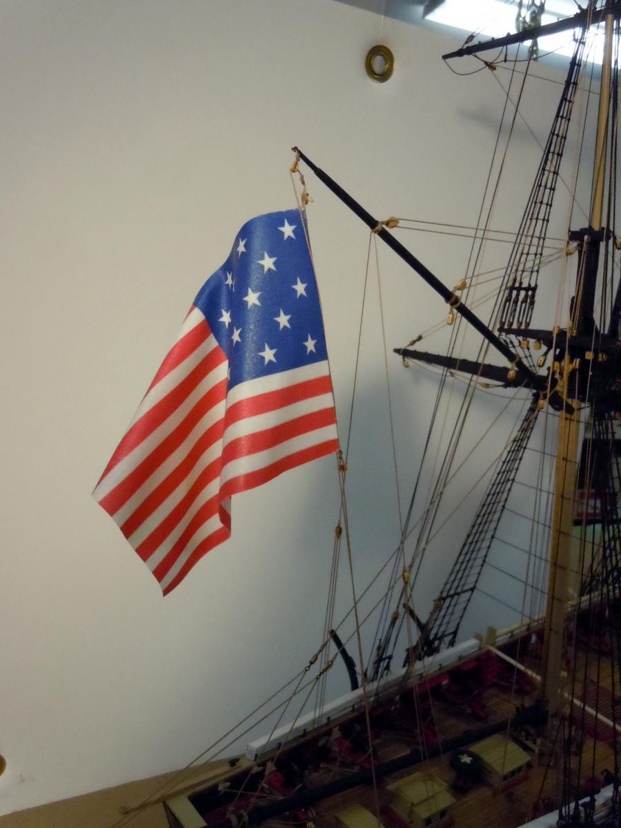
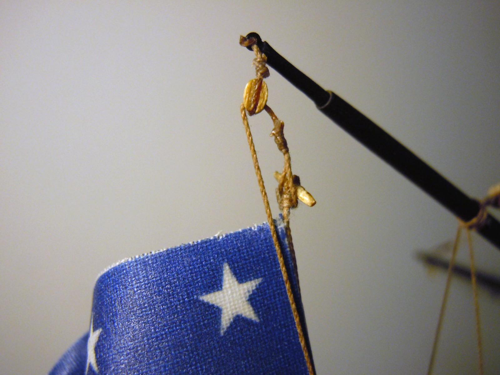
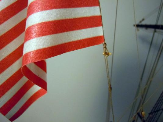
Thanks David! Here is a quick update on the flag while waiting for things to set. I soaked the flag in warm water and then formed it at the angle of the flag halyard keeping in mind the drape down 90 degrees to ground. The formed flag was held in place with clothespins and allowed to completely dry to take a set. There was a slight release when the pins were removed and final adjusts made by hand. Here is the top flag attachment with the wood toggle on the flag and the loop in the line. Here is the bottom attachment point with the loop on the flag and the wood toggle on the line. This combination allow for removal of flag, adding more flags or having the line in place joined at the ends. Now back to working on the hammock rail covers; a great deal of knot tying and just tedious and slow.


- 440 replies
-
- 10
-
-
- niagara
- model shipways
- (and 1 more)
-
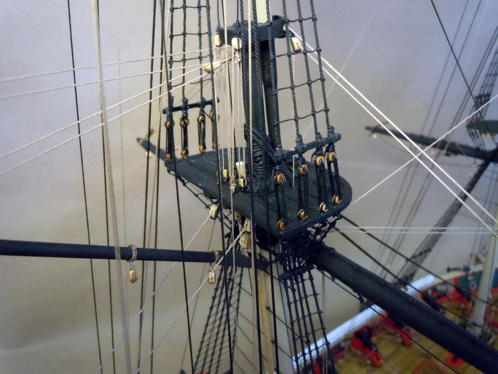
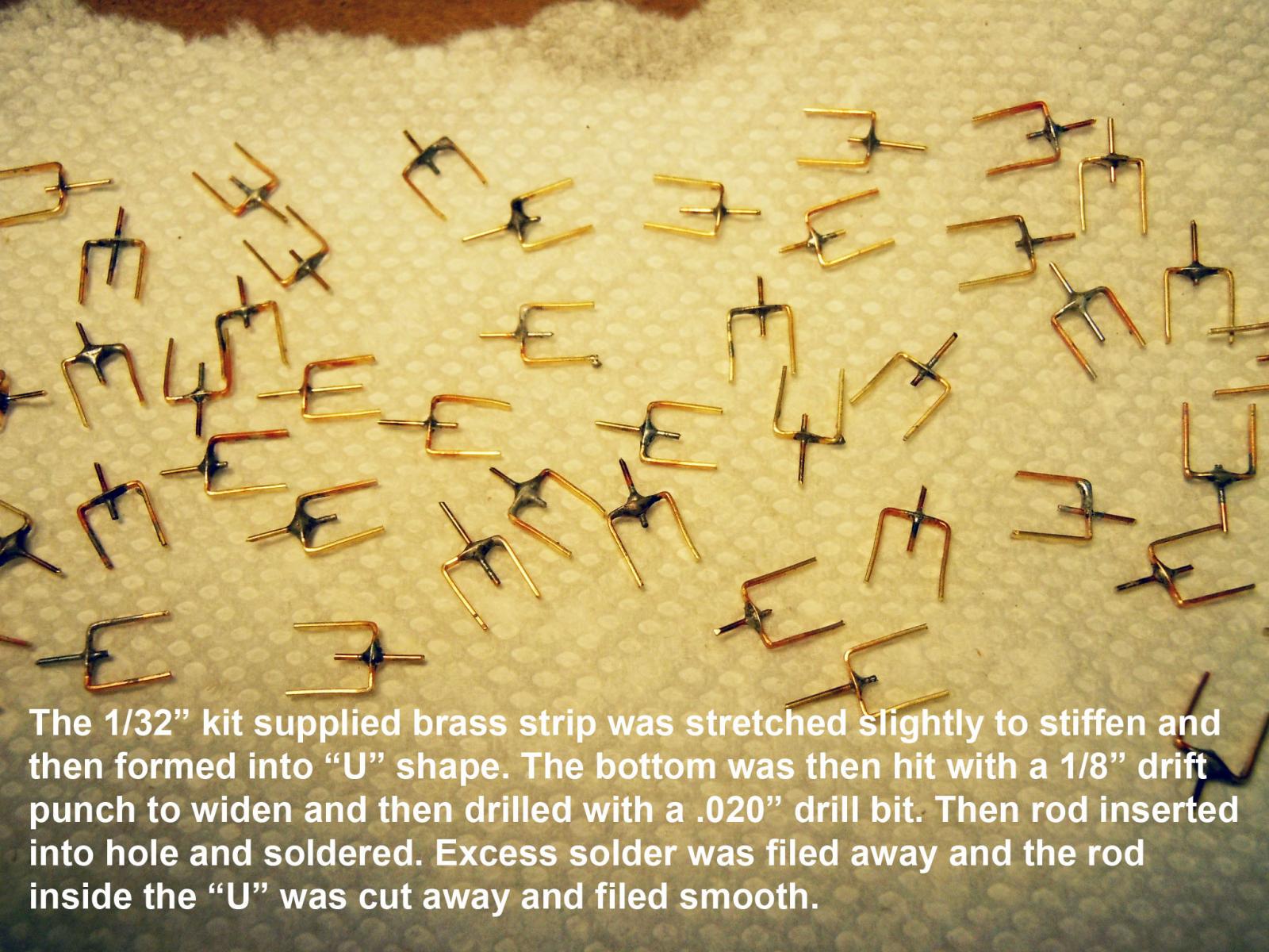
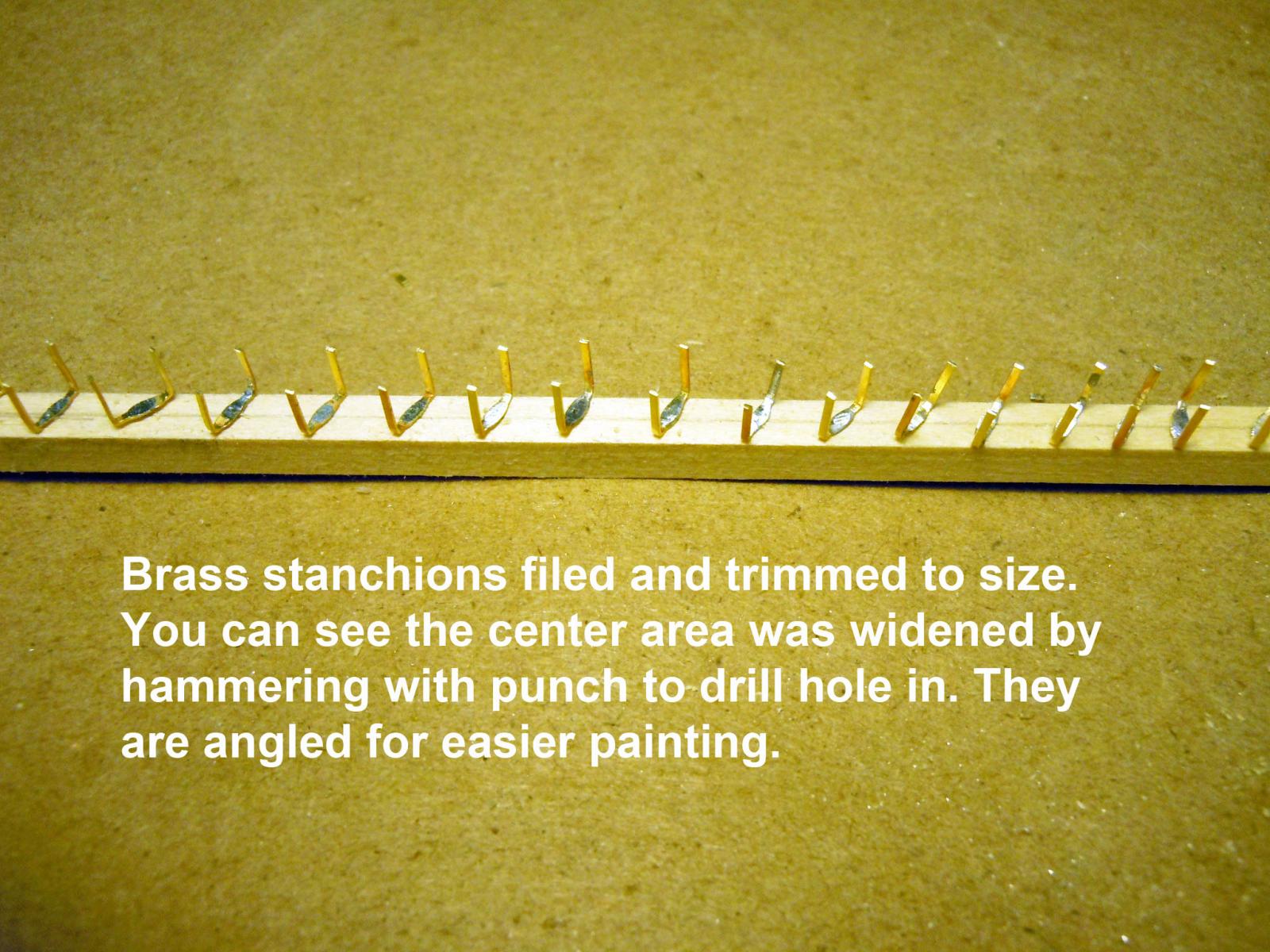
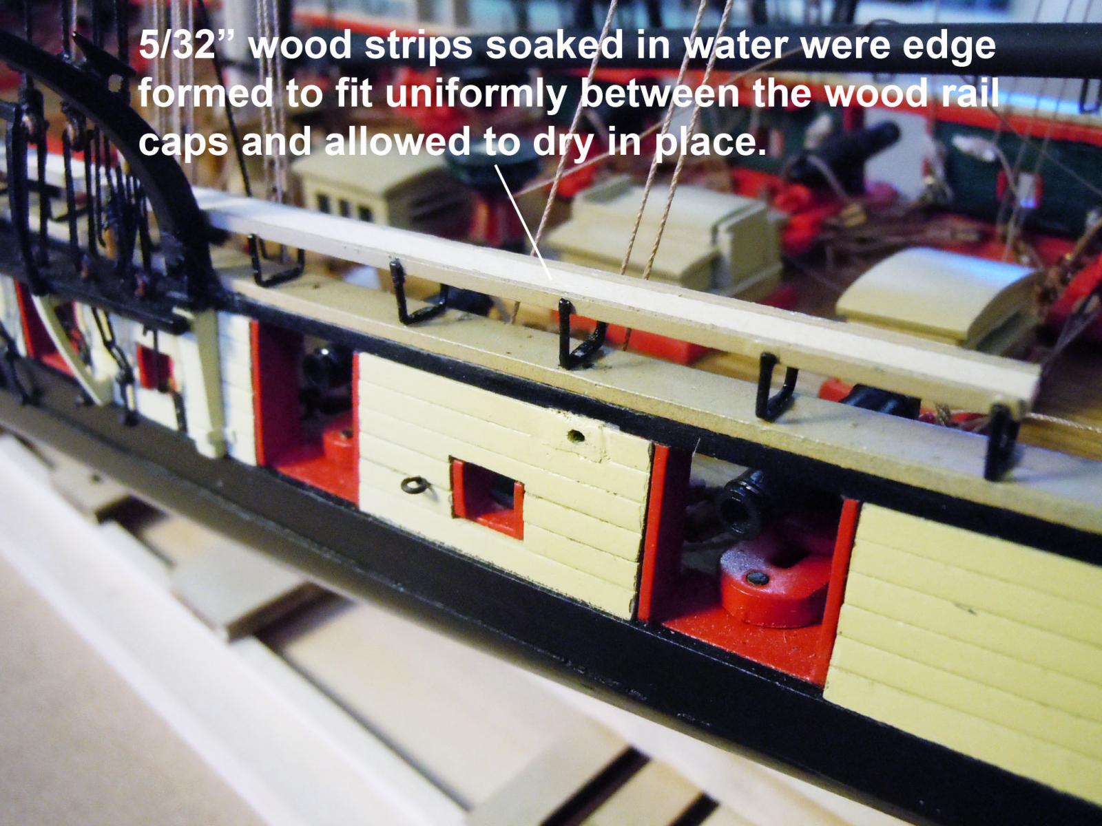
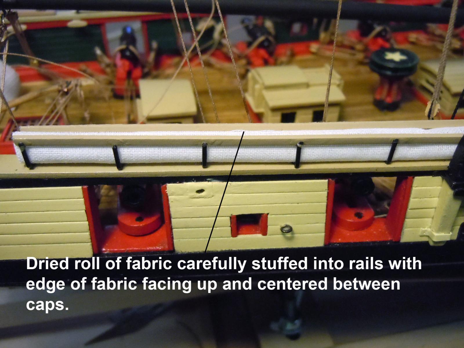
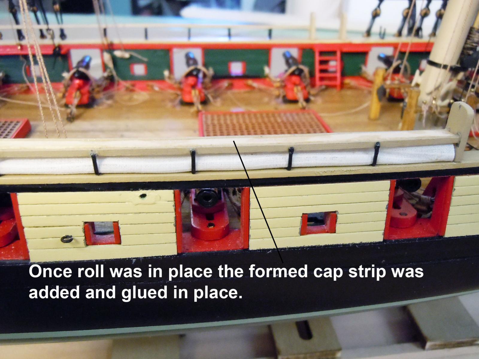
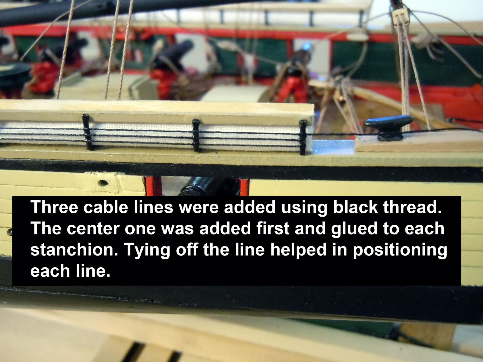
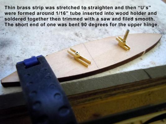
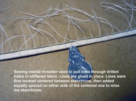
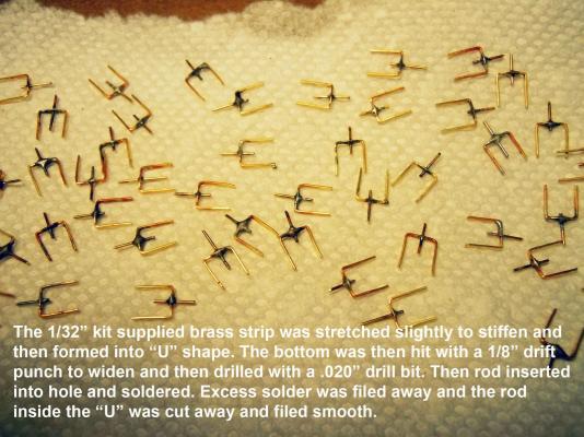
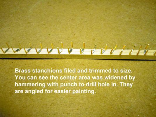
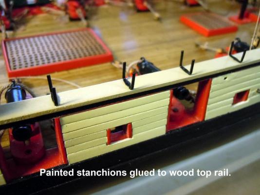
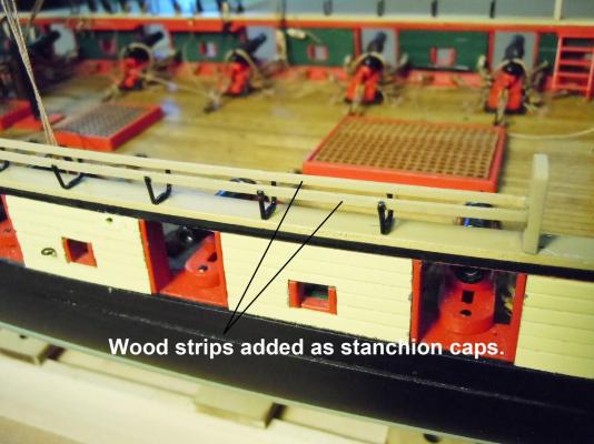
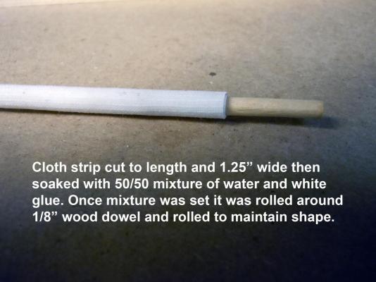
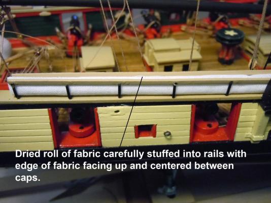
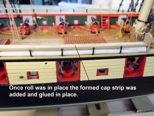
Well I moved onto the hammock rails and learned a lesson for the future; if these are on a ship do them before rigging the masts these would have been much easier to build in place. Anyway I was able to get them to this point working around all the existing structures and lines. First I stretched the 1/32" brass strip from the kit to straighten and stiffen to be much easier to work with. One end held in a vise and the other with pliers and slightly pulled. I then formed the brass into "U" shapes by marking the depth on the jaws of needle nose pliers and bent them; trimmed the two sides to length using a strip of wood and cutting with cutters. Once formed the center flat was hammered with a 1/8" drift punch to provide a wider surface to drill with a .020" drill bit to provide a hole for a locating pin which was soldered, cleaned and trimmed. While waiting for the Satin Black paint to dry I drilled all the location holes on the wood rail. Then I added the painted stanchions and glued them in place. Next I added the painted wooden cap strips to the top of the stanchions using CA. I had soaked cut pieces of the handkerchief the length of the each rail section and 1.25" wide. The dried stiffened piece was then rolled around a 1/8" dowel and rolled back in forth for the piece to retain the roll shape. The four were set aside for later use. Once the CA had set on all the stanchions; I hand edge formed 5/32" wood strips that were soaked in water and formed them to attain the curve in the rails; set in place and allowed to dry to take a set. Once the 5/32" strips were dry each one was individually removed and the fabric roll carefully pressed into place with the open end facing up and on center between the cap strips. Once the roll was in place and adjusted as needed the 5/32" top strip was glued in place. When all the caps were in place and the glue set I then added the cable lines to the outside stanchions by first securing one end to a cleat. I did the center cable first and then was able to space the bottom and the top cables using the center one as a guide. Next I will move onto the top covers which will be the harder step. They will be 1/4" wood strips formed to match the top caps, and will be fabric covered with securing lines tied off to the larger center cable on the inside.


- 440 replies
-
- 10
-
-
- niagara
- model shipways
- (and 1 more)
-
Everything looking nice and clean! Keep up the great job you are doing with the rigging.
- 270 replies
-
- 3
-
-
- red dragon
- artesania latina
- (and 1 more)
-
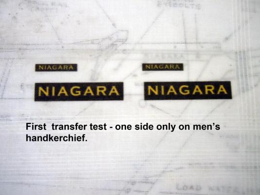
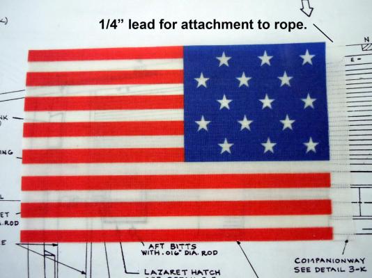
The t-shirt transfer paper worked great! Just follow the instructions. First I did the names to check that iron settings worked and they did. First I used spray starch on the handkerchief, use very light coats to avoid flaking when ironing. The starch stiffens for easier cutting with a very sharp Xacto blade and minimizing the edges fraying. Here are the names; keep in mind these are on a man's handkerchief hence the transparency and very light. I will spray backside first with Satin Clear to stiffen up and then with White to brighten up the Yellow in the letters. Another option for this using photo paper. Here is the two sided flag. I cut right to the perimeter so I could make sure both sides registered to each other. Then I ironed the first side per instructions and the turned over and ironed the second side. When cutting out, cut a 1/4" lead along the front edge for attachment first; then cut the other three sides. I am very pleased with how this experiment worked. Now to think about attaching while I continue working on stanchions. I may change the .008" line that I currently have to a heavier line more testing ahead.
- 440 replies
-
- 9
-
-
- niagara
- model shipways
- (and 1 more)
-
Thank you all for your kind compliments; the great thing is being able to share as well as, learn from each other on this site. The mast flag ropes are in place no big deal. I then decided to rig the anchors and with no reference on the plans I looked at the fore deck as well as the reference pictures of the replica I concluded that the only open space for the anchor ropes was as shown on the replica ship. Here are the steps in coiling the .045" anchor rope. First I determined that a coil diameter could be no larger than 7/8". I then soaked two 36" long lengths of rope with water and suspended them with a weight and allowed to thoroughly dry. This removed any memory of being coiled from Chuck's packaging and easier to coil. Next I soaked a length of rope with 50/50 white glue and water and carefully started coiling on a piece of plastic bag (glue does not stick to the plastic film) up to 7/8" coil. I then let this first layer dry completely. Once dry, I added CA to the inner rings of the coil to hold them together. Wetting of the second layer will unravel the first one. Avoid CA soaking the outer ring because this will change the rope finish. I worked with the anchors already rigged in place so as I coiled rope the length got shorter thus I added shims to take up the difference and support the coil as I worked up. The second layer was added indexing between the lower coil's rope and allowed to dry and CA added. More shimming for the third layer of the coil and keep in mind the length from the anchor to the coil in place. Once the third layer(top) is in place allow the glue to dry and DO NOT ADD CA to the top layer. Lay the rope soaking it with the 50/50 mixture from the coil to the anchor using a paint brush to apply the mixture and poke the rope down and in place. Repeat for the second anchor and glue the second on top of the first and lay the rope from the anchor to the coil; note due to the difference in height the second coil's top layer only fills out about two thirds of the top and is not a full layer. While waiting for all the steps above to dry I worked on the flag design and lettering. I am going to experiment with fabric transfers used for T-shirts to make the flag. I purchased the pack of transfer paper at Staples, Avery product number 8938. Will let you know how that works. The flag is 3" high. I also added the names both bow and stern sizes. Note a reverse is included for those who wish to make decals. Please feel free to copy this artwork and use for yourselves. Please no copying for resale. Added cleaner artwork. Now on to the the hammock rails and stanchions.


- 440 replies
-
- 6
-
-
- niagara
- model shipways
- (and 1 more)
-
George, I get most of my brass needs from these folks but keep in mind they have a $20.00 minimum so plan your purchases. http://www.specialshapes.com/ If you have a particular need and do not see it listed ask; I have gotten 1/32" tubing from them. Shop around their site you may find some interesting items. Enjoy!
- 440 replies
-
- 3
-
-
- niagara
- model shipways
- (and 1 more)
-
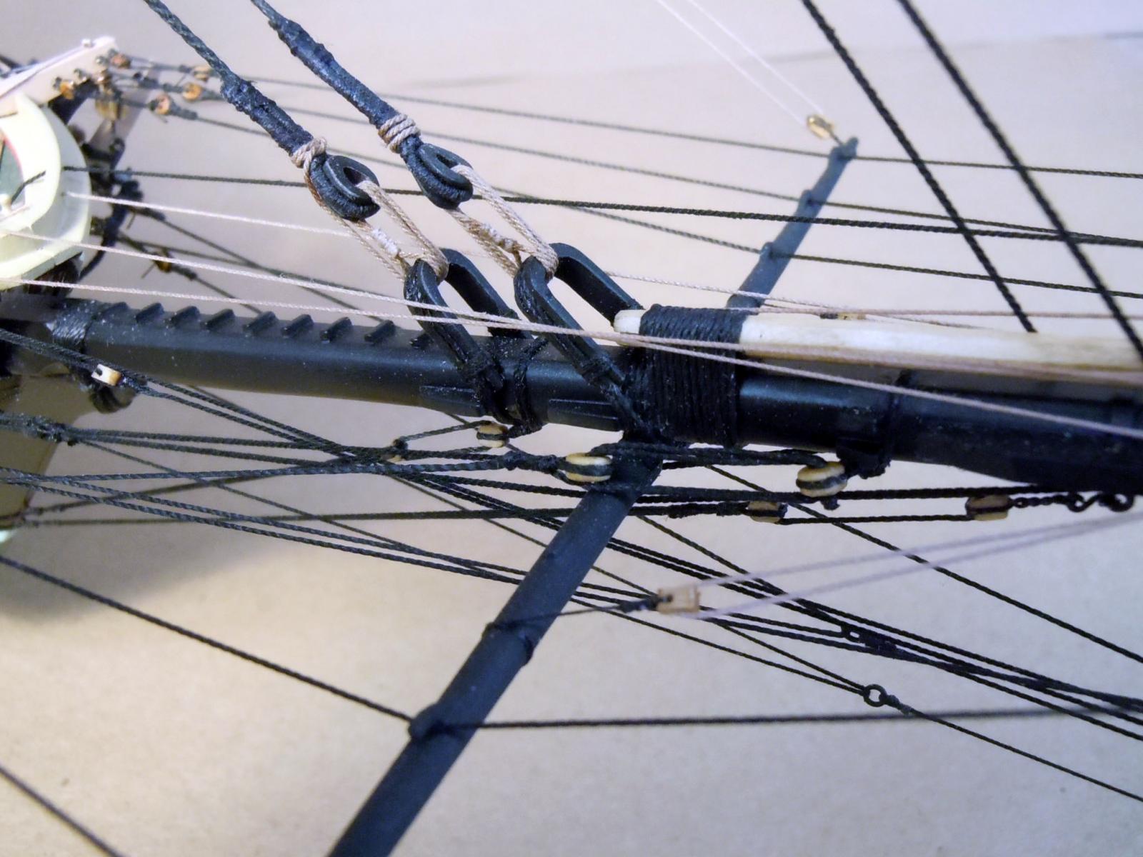
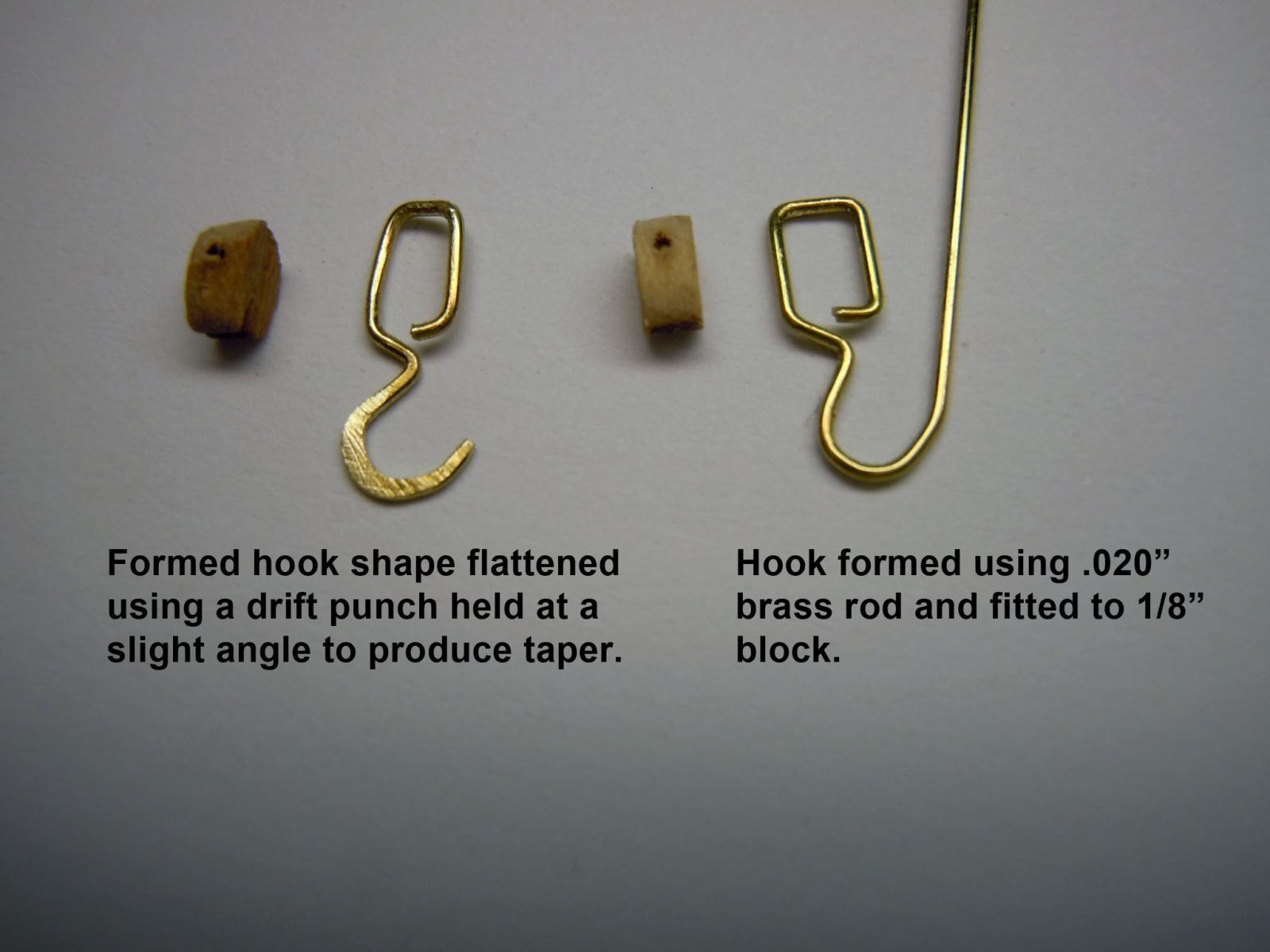
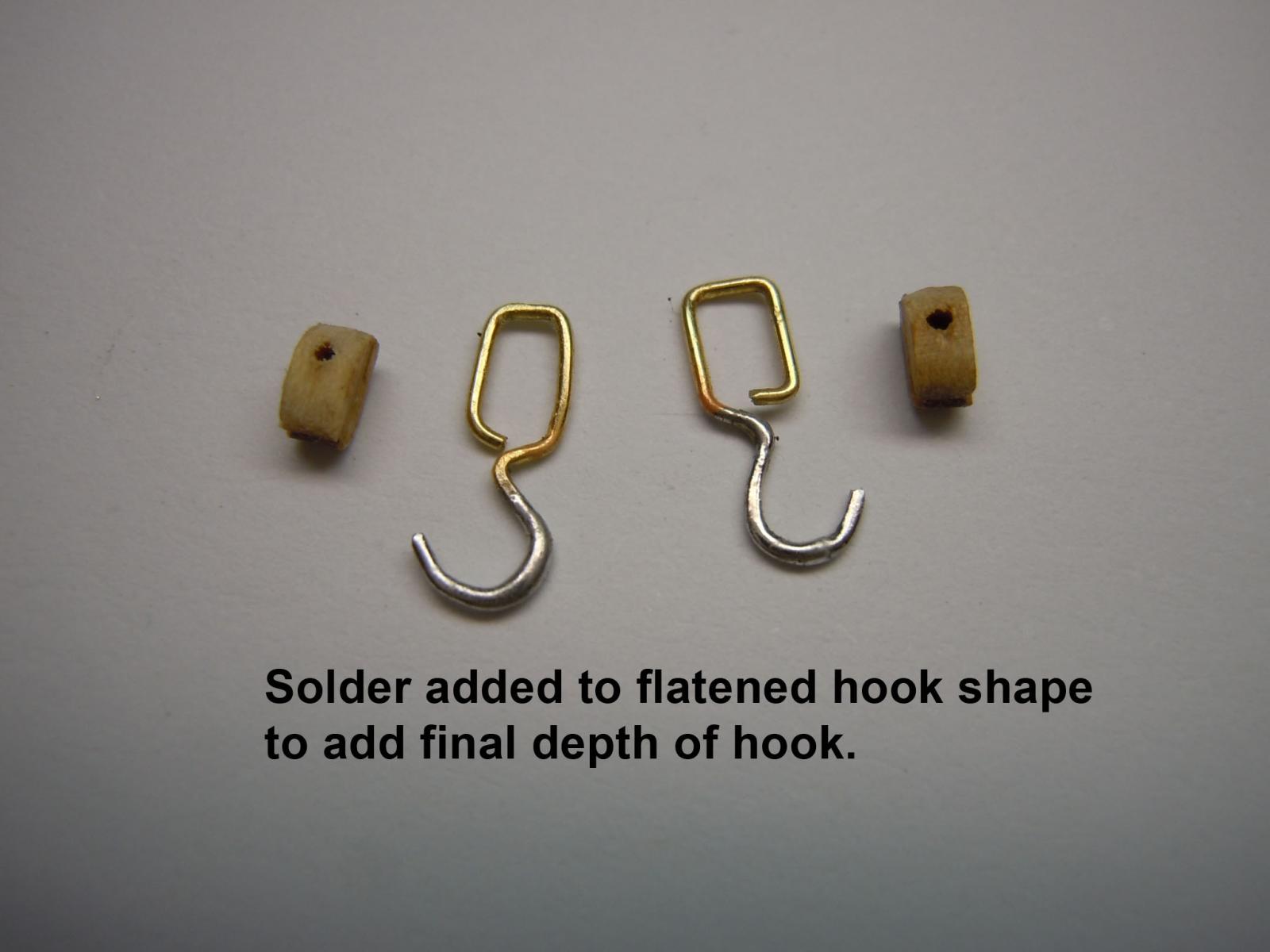
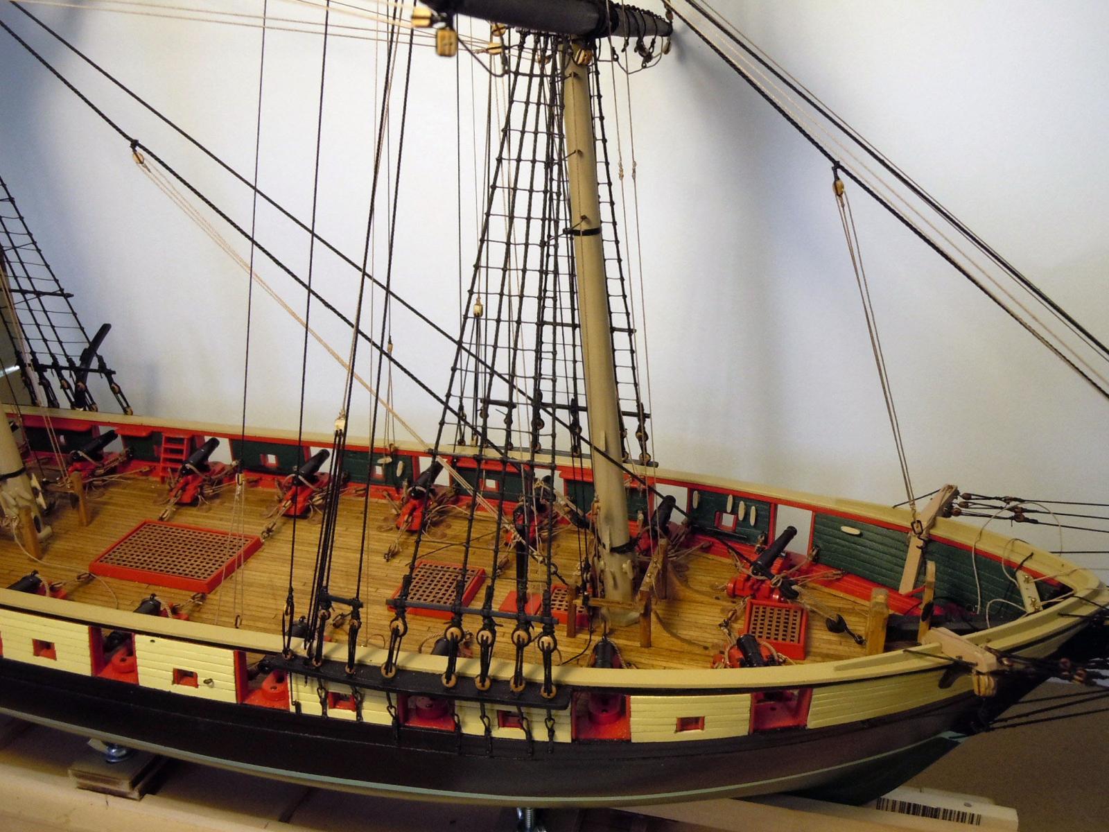
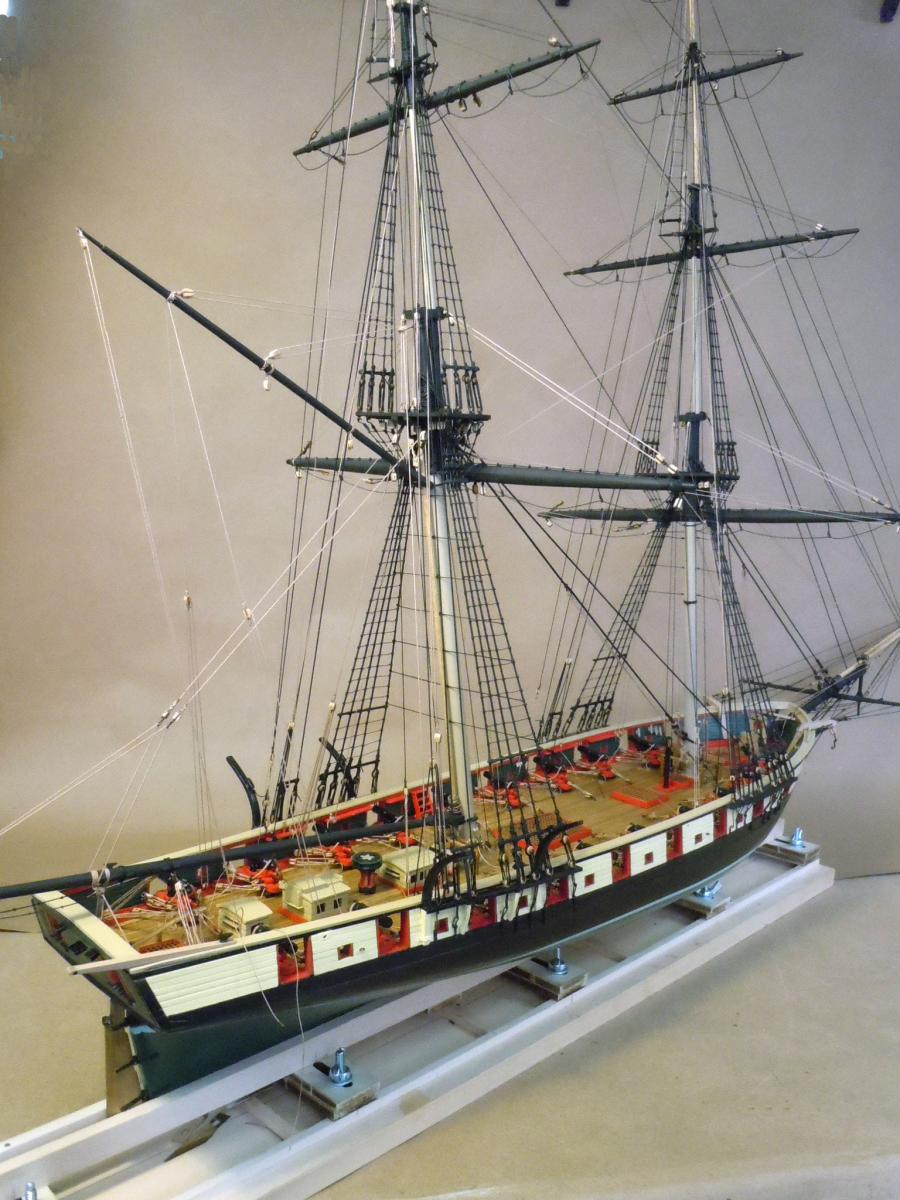
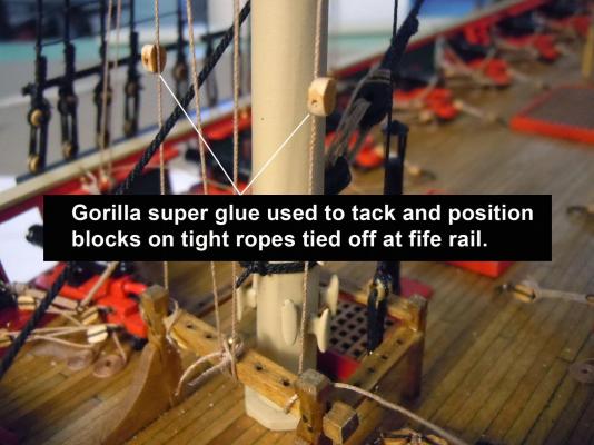
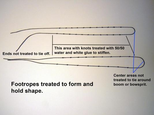
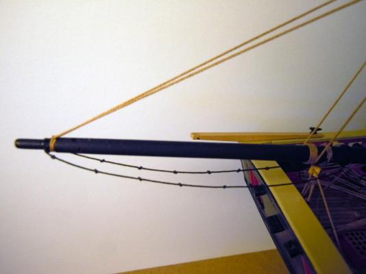
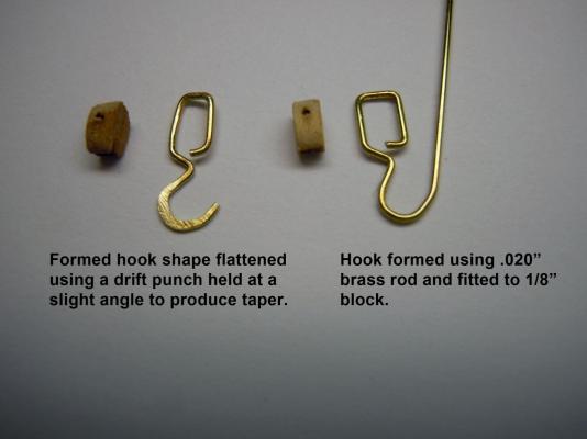
Finished up all the yard bracing, added the foot ropes and crane lines and cargo lifting hooks. For the benefit of novices that will follow building this I will share a couple of techniques used. First in adding the lifting lines I found I had to add blocks to existing down lines. First I secured the lines with a little stretch to tighten the lines; then I added a touch of Gorilla Super Glue which is thicker and allowed the ability to position the blocks and tacky enough to hold onto the line. Once glue set then wrapped and seized in space. I then added the foot ropes to the bowsprit and spanker boom. This required tying a series of knots on the line. First I did a test clove hitch on the ends to determine how much line needed to be able to use one line with the center area untreated with a mixture of 50/50 water and white glue. I then tied the knots for each side and only soaked the knots and one space at each end of the knot series. I allowed the glue mixture to set while weighted down overnight. I first tied the clove hitch to the end of the bowsprit and boom using the untreated center section; then tied the loose ends as needed and carefully formed the knotted areas to curves. Next I added the cargo hooks and rigging. I formed the hooks using .020" brass rod and needle nose pliers around to hold the single block. Once cut from the rod I hammered the hook shape with a drift punch at a slight angle to allow for a taper to the hook shank. I then added solder to each side of the hooks to fill out the body of the hook. I still do not have a good photo area so here are a few overview pictures of where I am at now with the above additions. Next I will add the flag lines to each mast and then rig the anchors and down the road the hammock rails and stanchions.

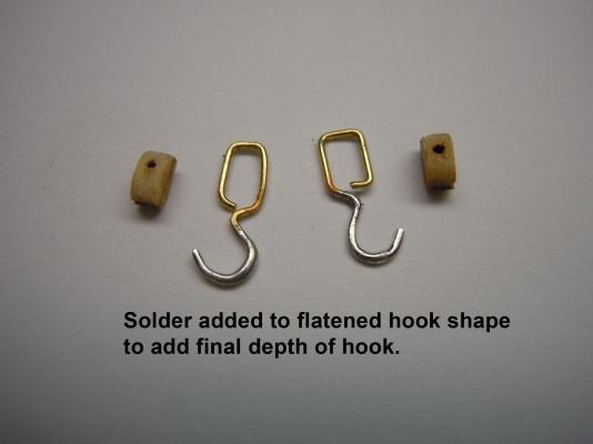
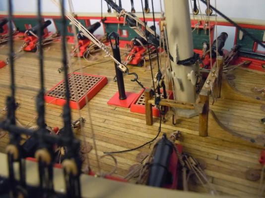


- 440 replies
-
- 13
-
-
- niagara
- model shipways
- (and 1 more)