HOLIDAY DONATION DRIVE - SUPPORT MSW - DO YOUR PART TO KEEP THIS GREAT FORUM GOING! (Only 24 donations so far out of 49,000 members - C'mon guys!)
×

Morgan
-
Posts
546 -
Joined
-
Last visited
Content Type
Profiles
Forums
Gallery
Events
Everything posted by Morgan
-
 If I had to pick one fault, which I will, it’s why run through Dalby Forest? It’s much nicer if you walk and enjoy the scenery! BTW your Indy is coming along nicely as well 😁. Gary
- 587 replies
-
- 1
-

-
- Indefatigable
- Vanguard Models
- (and 1 more)
-
Certainly the film Master and Commander shows chain pumps in use, you’ll confuse non nautical nerds if you don’t offer them 🤓 Gary
-
Interestingly (or not 😉) we overcame this in the Electricity Transmission sector with the guys who climb the lattice towers / pylons, they are equipped with two very large Caribiners on separate lanyards and the mantra was ‘clip on clip off’ with the alternate lanyards so you were always secure. Watching them climb was like watching a mountaineer using an ice pick in each hand only a lot faster! Fair play to anyone who climbs heights, I like to cuddle terra firms whilst watching others. Gary
-
That is a very cheap solution compared to the likes of Shapeways and Model Monkey
-
I’ve had both period and modern fittings direct from Model Monkey and have found both the quality and service to be excellent. Gary
-
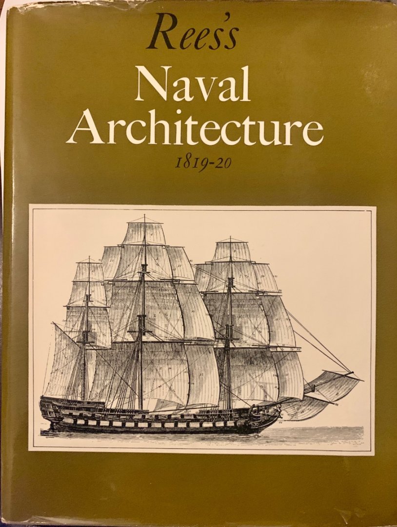
A cheaper source for a hard copy of some of Steel’s plates, if you can obtain a copy, is ‘Rees’s Naval Architecture 1819-20’ you may be able to locate one online. This is a compendium work abstracted from Rees’s cyclopedia which was issued over the course of the first 2 decades of the 19th Century, it abstracts all the naval architectural works from a wider serialised publication. The fold out drawings are the same Steel drawings which points to Steel’s successors being the contributors to this work. It has all the Steel plans for a 74-Gun Ship of the Line, and the profiles only for a 38-Gun Frigate, an East Indiaman, and a Royal Yatch, I’d say the scale is approximately 1:96, so not as large as Steel. My copy is a 1970 reprint for which I paid £30 last year. Gary
-
Glad your research and enthusiasm is gaining momentum Ian. I never cease to be amazed by the detail and atmosphere contained in Frank Hurley’s works, I have a couple of his prints hanging on the walls. For ostensibly ship pictures even my wife likes them. They are truly inspirational in my view. Keep up the research and I look forward to a forthcoming build log. Gary
-
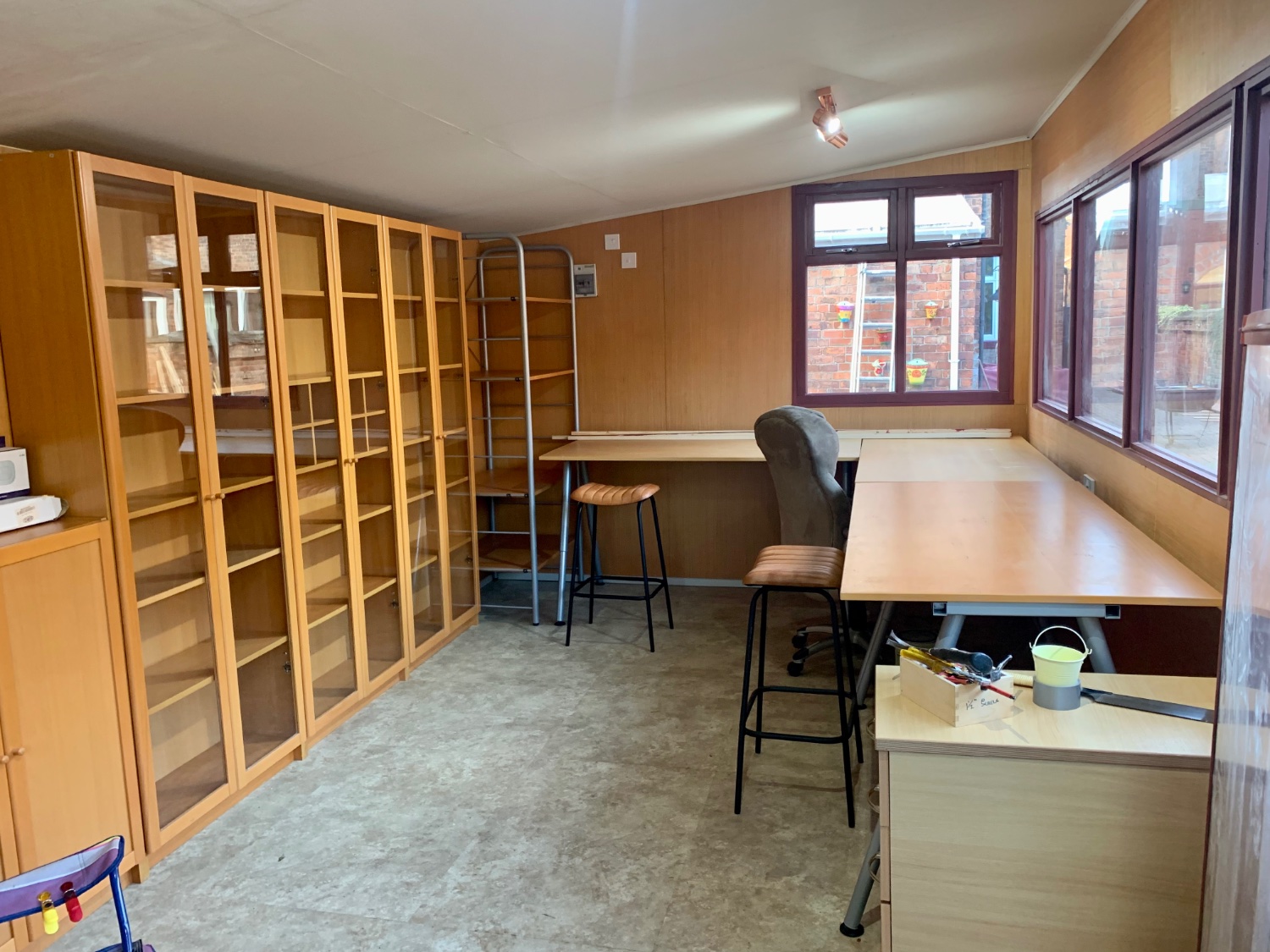
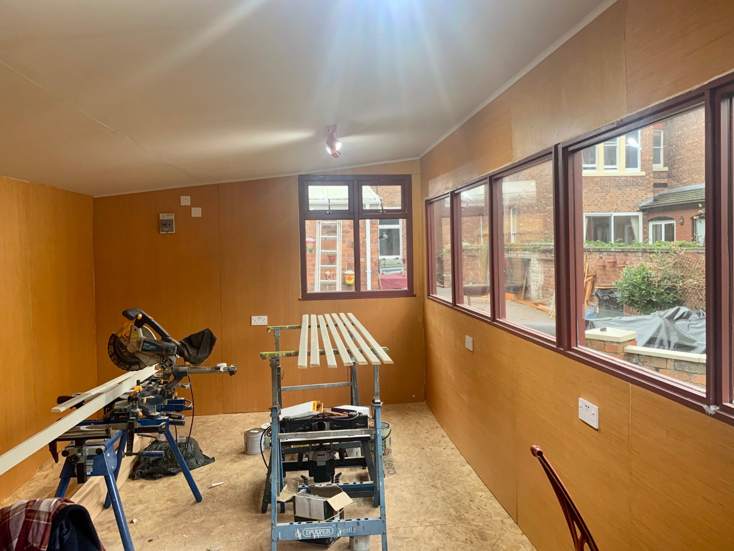
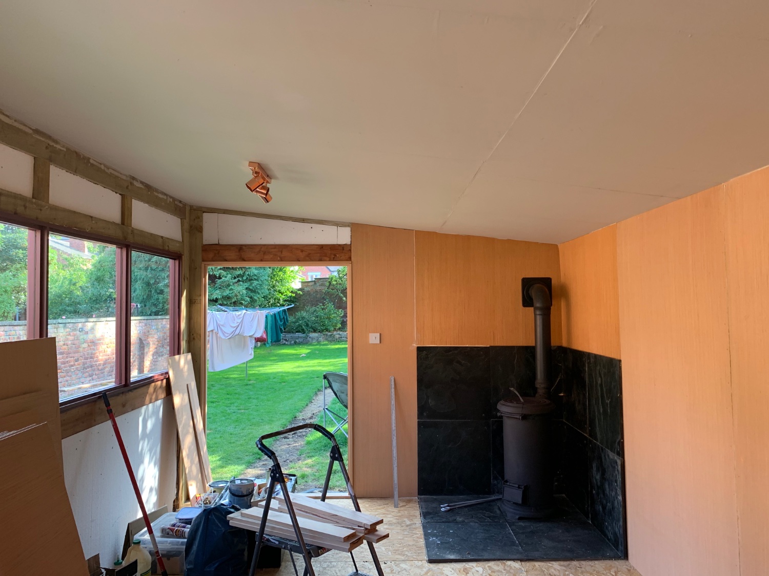
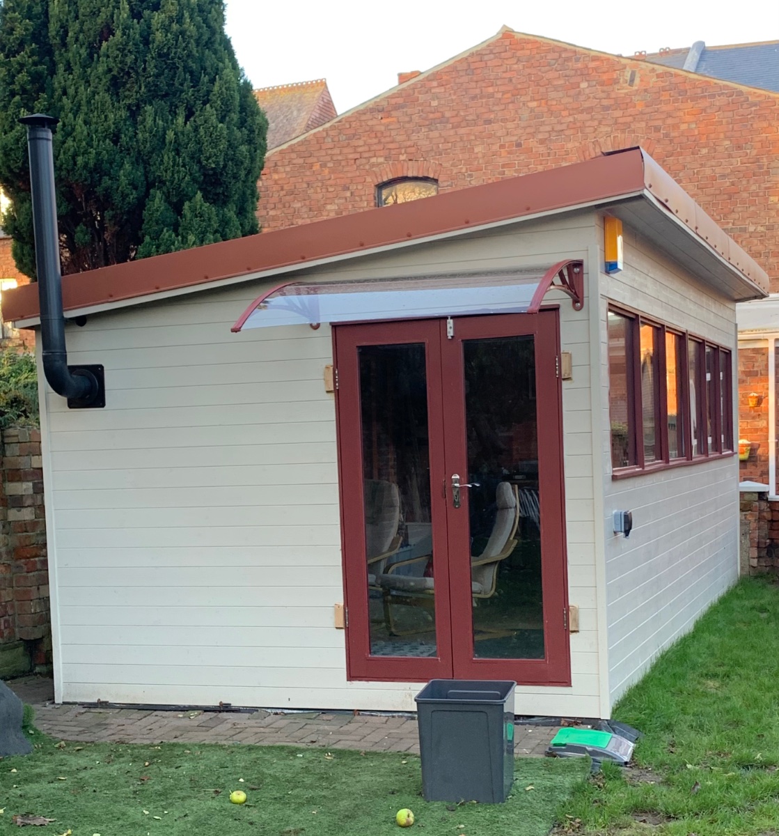
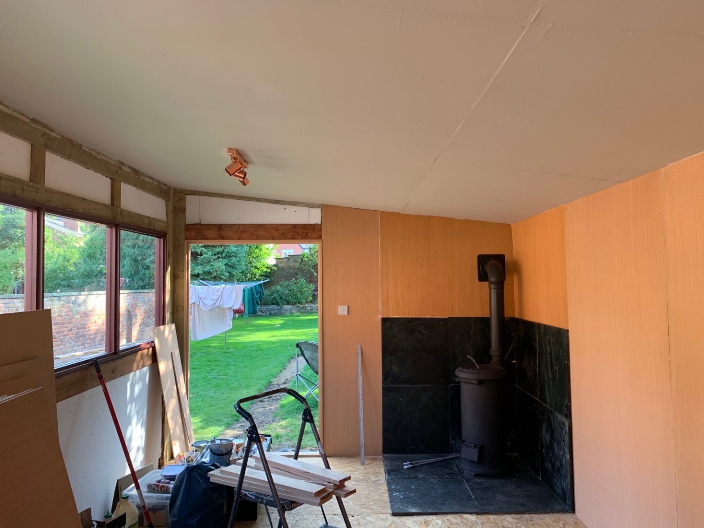
I’ve just refurbished one of those ‘dodgy’ stoves and installed it into a dodgy Garden Studio I just built this summer for modelling and other craft work, it kick out the heat. I can remove the top plate and boil a kettle and have done baked potatoes on top. Perhaps a Dutch Oven next for a dodgy stew! The dogs love it, and I have to fight my way through the pack to feed the stove! Gary


- 227 replies
-
- 13
-
-

-
Aw come on guys, after viewing his ship of the line I wanted to see pictures of his cars, and his virtual house 😂 Sorry, sarcasm is the lowest form of humour, but given the hubris of the man he deserves it, I’ll resist in future, maybe 😈 Edit: Moderators may be wise to delete my post and lock this thread.
-
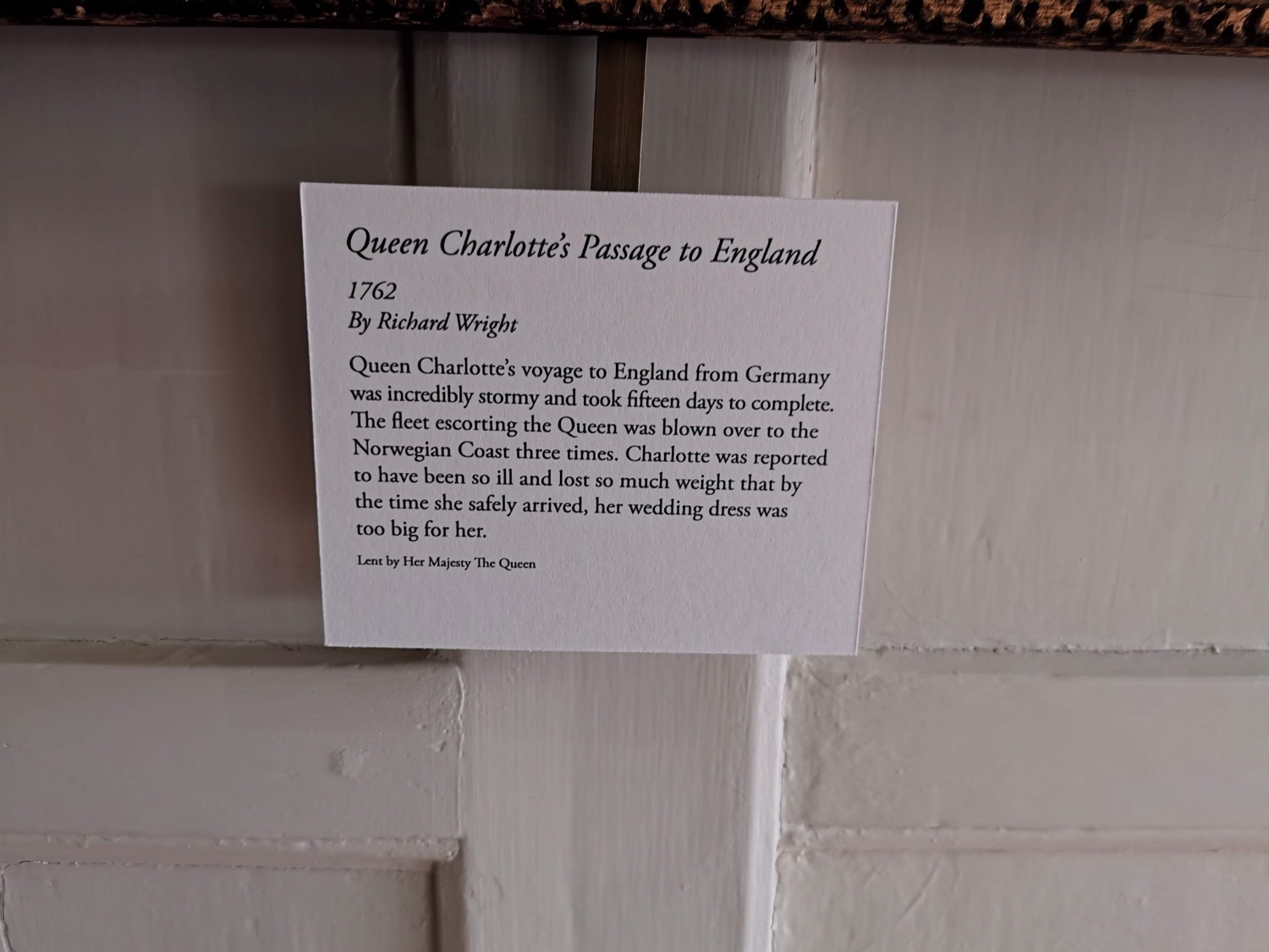
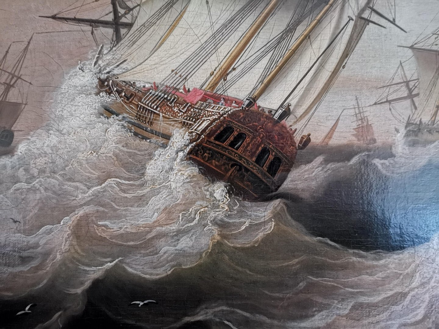
Thor, A few years ago when visiting Kew Palace I came across a contemporary painting of the Royal Caroline. Its subdued colours in comparison to other contemporary artefacts suggests it could have been painted from real life. It confirms what Mark says. I did post these here several years ago so you may already have seen them. Gary

-
Dave, I see you are also NE based, an occasional source of books is Barter Books at Alnwick. Whenever I am up that way I call in on the off-chance. I have picked up several AOTS books over the years at reasonable prices, together with some rarer and more expensive specimens. It’s hit and miss like any second hand book store, but worth calling whenever you can on the off-chance. Gary
-
Dave, You won’t get rigging diagrams from Steel, think of it more as a Specification than a diagrammatical work, and paperback / online versions will give you all the tables for masting and rigging anyway, although, beware there were several dated issues reflecting the evolving standards from 1794 onwards. The full work has 95 plates, but many are on ship type, naval tactics and sailmaking. You will get a better idea at https://simcomfort.co.uk/rigging.htm, but you would need deep pockets for this full reprint at £475! However, the quality is excellent. Gary
-
That image of those figures is unfortunately of Russel Crowe and Paul Bettany, I don’t think Chris could afford the image rights! Gary
-
which mini wood lathe is best?
Morgan replied to Benjamin S's topic in Modeling tools and Workshop Equipment
Hi Benjamin, Perhaps think about what your immediate needs are for the next few models you intend to build, and use this to decide the size and complexity of lathe you need, narrow down your requirements. If you only intend turning cannon in the near future for example you can get away with a very small metal working lathe, if you want to turn masts and spars then you will need something with a longer bed. Consider a phased approach and trading up to a larger lathe as your skills develop, this way you could buy a second hand lathe to get you started, which will have more features than a brand new lathe for a similar price. I am sure if you can elaborate on what size and type of fittings you want to make you will get more specific pointers from knowledgeable forum members. Gary -
Hello Ian, Welcome to MSW. I would search the forum first for other Endurance builds and see what, if any, original research others have done. Secondly, if you can’t find what you are looking for have a look at the photographs of Frank Hurley, you may be able to estimate plank widths from features on board, his photos have excellent definition. You can’t beat your own research, it can be as rewarding as the build. Thirdly, to get a feel for the period I’d recommend a visit to RSS Discovery at Dundee, obviously a different ship, but of the same era and function. These ships were built for a specific narrow purpose to operate in Arctic and Antarctic waters, built for strength, not to look pretty, so I would avoid getting side tracked by some of the dandified planking finishes you will see here, they would not be appropriate. Gary
-
I don’t know what your figure painting skills are like BE, but the dark monotone figure works well for display purposes, it shows off the barges purpose but doesn’t detract from it. Perhaps have a dark monotone crew first and see how it works, I think it could be quite interesting. Gary
- 106 replies
-
- 3
-
-
- Admirals Barge
- Vanguard Models
- (and 1 more)
-
I think the Centurion would be a fantastic subject, the ship deserves a higher profile than she has, and her exploits under Anson are a good read, one of those instances where reality is more outrageous than fiction. Gary
-
BTW - regarding a possible HMS Centurion - as in Anson, as in circumnavigation of the globe and capturing a Manila Galleon? Gary
-
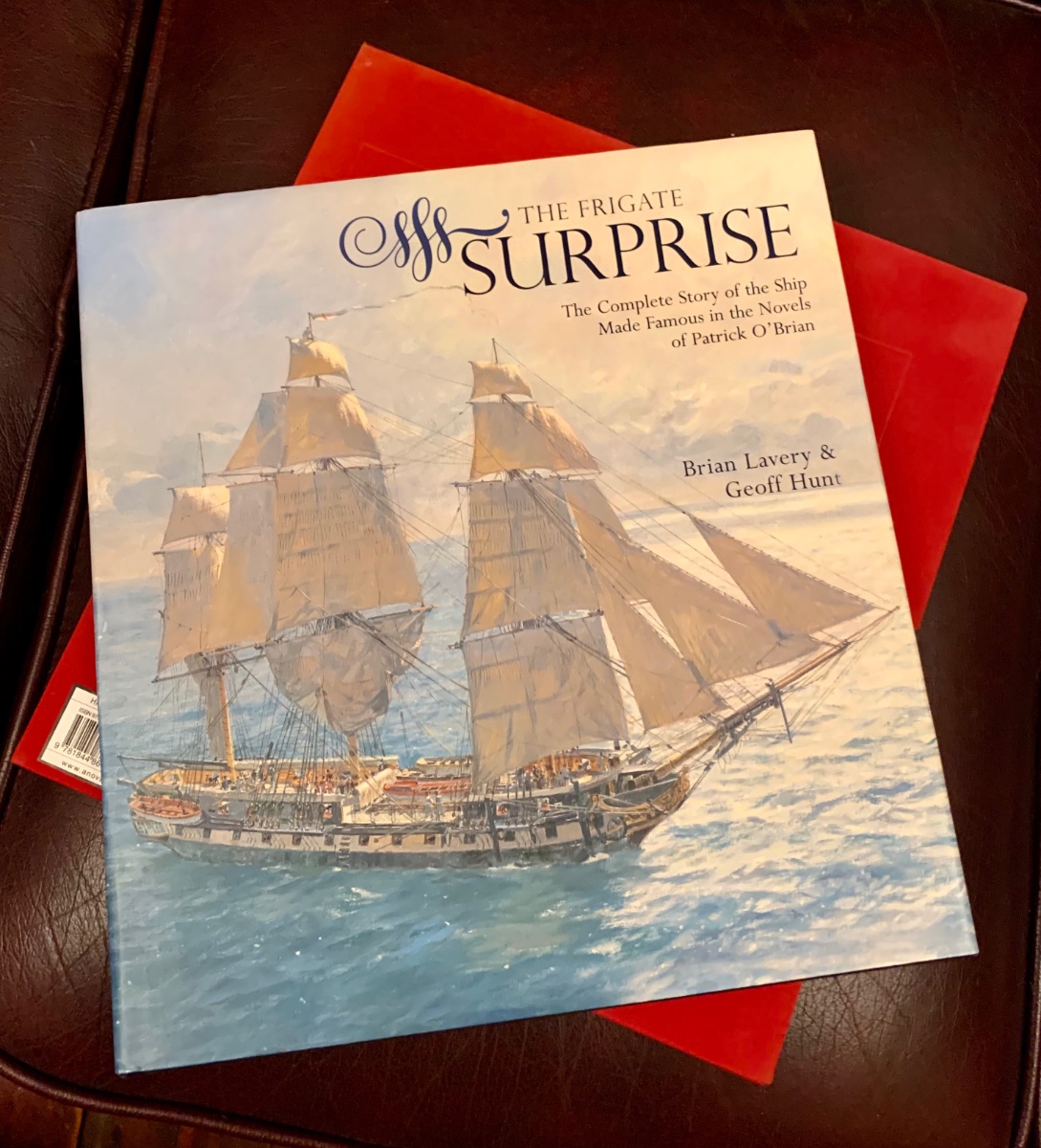
Time to start revising for this one 🫣😲😁 What better reason to re-read the series, but for the revision I recommend this book, I bagged one of the signed limited edition 🤤

-
So make 1 gallon (just enough to kill a few bugs or burn down an house) and spray it indiscriminately, you don’t need to aim it at your victim, the fallout will kill them! I think napalm is more surgical. Gary
-
According to Caruana that is correct, for a 32-Pounder a single and a double to both running out tackles, and also the same for the train tackle. For the 24-Pounders and below only single blocks on all tackle. Gary
-
Royal navy - stern colours?
Morgan replied to Vane's topic in Painting, finishing and weathering products and techniques
Those yellow stripes had their genesis in the 1920’s following her restoration as a chromium yellow, a paint that didn’t exist until the 20th Century, so care needs taking when using reconstructed resources, it looked nice but technically impossible. I’d rely on strictly contemporary paintings where possible, even then artistic licence has to be considered. Gary -
I think it’s more a question of why does the ship at Portsmouth have an entry port when she didn’t at Trafalgar! Answer - to let the tourists on and off. Seriously, contemporary evidence shows Victory had no side entry ports between 1788 and 1814. Gary
-
Victory
Morgan replied to Jake 1948's topic in Painting, finishing and weathering products and techniques
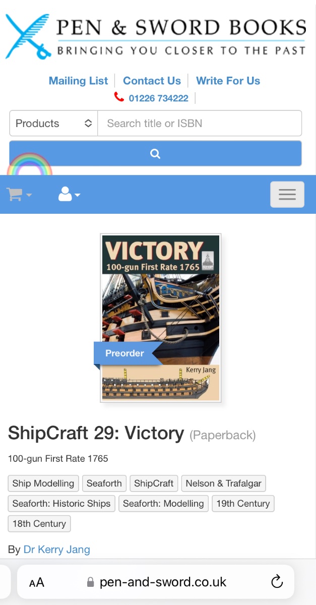
It may be worthwhile waiting a couple of weeks for a new book on Victory by Dr Kerry Jang who sometimes frequents this site, it may answer this and many other questions. “The ‘ShipCraft’ series provides in-depth information about building and modifying model kits of famous warships. Previously, these have generally covered plastic and resin models of 20th century subjects, but this volume is a radical departure – not only a period sailing ship but one for which kits are available in many different materials and scales. This requires some changes to the standard approach, but the main features of the series remain constant. Victory, Nelson’s flagship at Trafalgar, is probably the world’s most famous sailing warship, and survives in restored form at Portsmouth. With lavish illustration, this book takes the modeller through a brief history of the ship, highlighting differences in appearance over her long career. Detailed colour profiles reveal decorative detail and changes to paint schemes over 250 years, and outline some of the debatable features experts still disagree about. The modelling section reviews the strengths and weaknesses of available kits, lists commercial accessory sets for super-detailing, and provides hints on modifying and improving the basic kit, including the complexities of rigging. This is followed by an extensive photographic gallery of selected high-quality models in a variety of scales, and coverage concludes with a section on research references – books, monographs, large-scale plans and relevant websites. Following the pattern of the series, this book provides an unparalleled level of visual information – paint schemes, models, line drawings and photographs – and is simply the best reference for anyone setting out to model this imposing three-decker.” Gary
-
Victory
Morgan replied to Jake 1948's topic in Painting, finishing and weathering products and techniques
If you are painting the Victory after the present ship then the gunports are black outside with red inside and red edges. Internal / external metalwork is the same as prevailing gunport colour red inside, black outside. If you want historical accuracy at Trafalgar the gunports were hull coloured outside, so yellow ochre, and red inside / to the edges. You can check this against the great contemporary paintings of JMW Turner and Clarkson Stanfield. Turner certainly saw Victory first hand post battle and his preparatory sketches confirm hull colour, Stanfield was guided by Trafalgar veterans, including Hardy himself. The black gunports were a post Trafalgar tweak to the colour scheme arising from the belief they were black, in fact this was a misinterpretation, the black contrast effect was achieved when the gunports were raised and Victory bared her teeth, this would produce the chequerboard effect. This became the prevailing RN colour scheme post Trafalgar but has become mistakenly synonymous with Nelson and Trafalgar. Gary