Morgan
-
Posts
546 -
Joined
-
Last visited
Content Type
Profiles
Forums
Gallery
Events
Everything posted by Morgan
-
 The only artist who both visited Victory after Trafalgar and produced paintings of the ship was JMW Turner. In his paintings he shows a light yellow ochre and a greyish black. This is in keeping with Flyer’s post above on scale and is what I believe you would get were you to tone down her present colour scene. Attached below is a screenshot of Turner’s Battle of Trafalgar. Gary
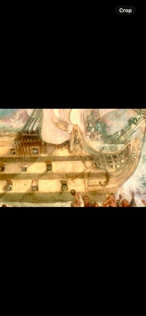
-
Hi BE, Absent specific evidence it is anyone’s guess, so no right and no wrong. I would say of the Victory as discussed above it wasn’t until refit of 1787/8 that the QD extension around the Mainmast was removed, so not that far removed from the Indy razee. I was actually lucky enough to get on a behind the scenes tour of Trincomalee recently, access to the forepeak and gunners store, pump well and other areas of the hold normally off limits. This freshens it when you’ve bream aboard as many times as I have. Currently they have a small exhibition of items recovered from the wreck of the Invincible, but we are awaiting the extension to the Museum that is in the planning stage which will see a large increase in size. I know they plan to bring up the Sim Comfort sword collection they recently acquired, as well as adding more modern naval exhibits. No dated for all of this as yet unfortunately. Gary
- 648 replies
-
- 4
-

-
- Indefatigable
- Vanguard Models
- (and 1 more)
-
Hi BE, The RN had experience of dealing with masts is this situation, usually the Mainmast when the QD finished abaft of it. The solution was to build a small island projection out from the QD. You see this on several NMM models such as Victory, Royal George and Royal William - I haven’t searched further. I attach a screen shot of SLR0512 (Victory) as an example. I don’t see why Indy wouldn’t be fitted any differently. It lifts the deck working of the mast out of crowded area your model highlights. Gary

- 648 replies
-
- 2
-
-
- Indefatigable
- Vanguard Models
- (and 1 more)
-
Hi Tom, The only evidence I can find states rope, and no mention of any attachments. It is important to note that fresh sea water was used regularly to wash down the ship so if these ropes were used in conjunction with wash down water the regular flow of water would prevent silts building up and blocking the limber holes. In relation to this whole topic this is what the Royal Navy ‘Regulations and Instructions Relating to his Majesties Service at Sea’ have to say on the matter: “As cleanliness, dryness, and good air are essentially necessary to health, the Captain is to exert his utmost endeavours to obtain them for the ship’s company in as great a degree as possible. He is to give directions that the upper decks are washed very clean every morning, and that the lower decks are washed as often as the weather will admit of their being properly dried; they are to be swept twice at least, every day, and the dirt collected on them thrown overboard. The hammocks are to be carried upon the deck, and the ports to be opened whenever the weather will admit of it, and no more chests nor bags than shall be necessary for the comfort of the men shall be kept on the lower gun deck, that as a few interruptions as possible may be opposed to offer a free circulation of air. The ventilators are to be continually worked, and the hold and storerooms ventilated by wind sales. The ship is always to be pumped dry, the pumpwell frequently swabbed, and a fire, with proper precautions, let down to dry it. If the weather should prevent the lower deck ports from being opened for any considerable time, fires are to be made in the stoves supplied for that purpose, and the lower decks maybe scrubbed with dry sand.” I note there was a discussion on you limber hole thread about using the hold as a latrine, etc., if someone did so and was caught on a RN Ship they would be flogged, cleanliness was an obsession and there were, as mentioned above, enough hands to make cleaning the ship something akin to perpetual motion. Gary
-
Tom, Falconer’s Dictionary of the Marine, 1815 Edition: - “Limber-rope, a long rope, frequently retained in the limber holes of a ship, in order to clear them by pulling the rope backwards and forwards, so as to loosen any dirt by which they may occasionally be choked.” Bob does say his experience is of modern practices. I would imagine the limber rope may have had periodic knots, but can’t be certain. A rope in a silted contained channel could just pull through its own area and not actually move anything, but a knotted rope would provide the surface area to dislodge silt. Gary
-
To add to the conversation, First Rates like Victory had 850 crew, it was necessary to keep them busy and not allow them to stew over their confinement. Cleaning ship was one means of keeping otherwise idle hands busy and from fermenting trouble, so they did lots of it. There are no gun deck storage areas for cleaning equipment, this would have gotten in the way of having a clear area from stem to stern when cleared for action, so these items would have been stored in the hold. Gary
-
There was a specific screw jack supplied that fractionally lifted the beam and allowed the wooden stanchion to be removed. Victory does have some brass stanchions as well which are hinged and swung up out of the way, from memory these are in the vicinity of one of the capstans, I believe they are a later addition and can also be found on the Trincomalee. Gary
-
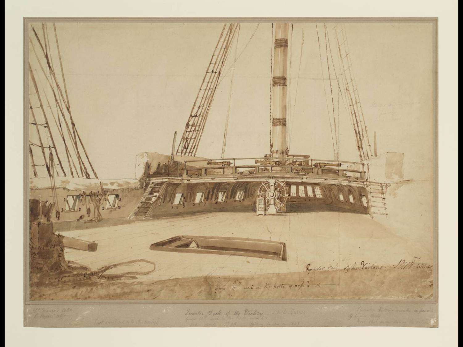
Hi Tom, Steel stanchions with rope. It seems the stanchions were fitted in to sockets so were demountable. Attached is a watercolour by JMW Turner of Victory’s quarterdeck done a couple of months after Trafalgar, you can see the stanchions to the stairs. The Poop barricade is steel as it had swivels attached, and is not a handrail system. The picture is from the UK’S Tate Art Gallery. Gary

-
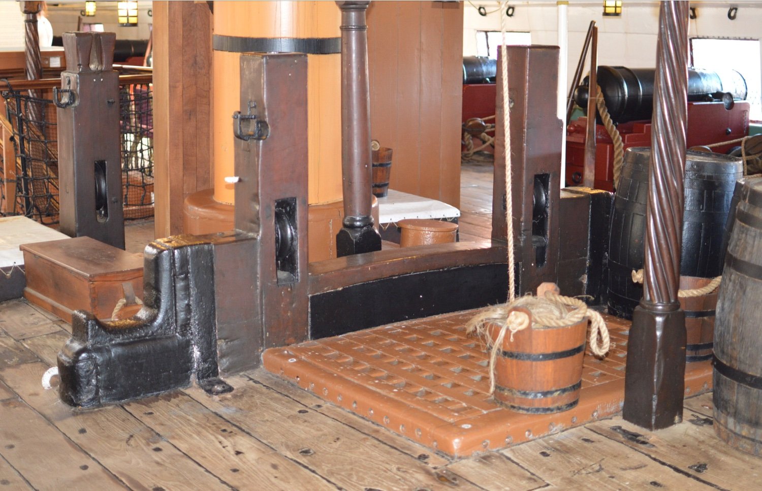
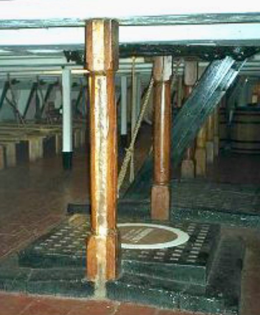
Looking at my photo archive of the UK’s 3 surviving historic ships, Victory, Trincomalee and Unicorn columns or stanchions in the Hold and Orlop are straight sided. The mess or berth deck on the 2 frigates could be either turned or straight (i.e. not turned). However, columns on the gun decks are always finished and turned in the centre section. I don’t believe there was a standard or pattern for this, other than being ‘custom and practice’, and down to the individual dock yard / constructor. The Trincomalee has the Wadia (Bombay constructor) barley twist columns, she also has the more classic turned columns which are probably a later addition. I’ve attached a photo below, I’ve got a scratch Trincomalee in hand and have no idea as to how I will reproduce those! The other 2 photos are from the Unicorn for comparison, one of the mess deck, the columns are crude in comparison to others, the second is of columns in the hold. So in summary, for Victory I would venture straight for the hold and orlop, and turned on the gun decks. Gary

-
Hi Rick, Elm Tree Pumps, also known as the common or brake pump were multifunctional. In a ship with chain pumps the Elm Tree Pump served to bring fresh seawater up for washing the decks and feeding the condenser on the stove. They could provide water for fire fighting on deck but they were only a lift pump and not a pressurised pump so couldn’t be directed at a fire as there was no head of water (ships had separate fire engines / pumps that could generate pressure and be directed at sails etc.) Initially the pump casing was open directly to the sea through the ships bottom, but in the late 18th Century they were brought inboard and a system of indirect pipe work via valves and stop cocks could let sea water in to the cistern around the mainmast and the foot of the pump was now inside the ship within the cistern to lift the water. In smaller ships without chain pumps the elm tree pump was the primary means of clearing water from the hold. They are called Elm Tree Pumps as it was the bored trunk of an elm tree that was used for the pump casing. Gary
-
Iron Braces on Hanging Knee Deck Supports... HMS Victory
Morgan replied to tmj's topic in Nautical/Naval History
Hi Allan, Steel’s plate 8 - X-Section of a 74 gun ship put things nicely into context, the following table aligns with the colour code, obviously this is for the whole ship. Your dimensions from Steel can be used to extend this. ZAZ0122 Colour Type No of Riders Red Top Rider 24 Red & Blue Long Middle Rider 2 Blue Middle Rider 20 Blue & Orange Long Breadth Rider 2 Orange Breadth Rider 22 Green First & Third Futtock Rider 32 Purple Second Futtock Rider 16 Rectangular yellow box below Green Riders[1] Floor Rider 8 Totals 126 Gary -
6-pounder, Royal Navy cannon barrel - George III era
Morgan replied to Gabek's topic in 3D-Printing and Laser-Cutting.
Very nice Gabe. 12 & 24 pounders next please 😜 Gary -
Iron Braces on Hanging Knee Deck Supports... HMS Victory
Morgan replied to tmj's topic in Nautical/Naval History
Hi Tom, The attached may help, it is the Victory’s Riders from 1788 around the Main Mast, each colour just denotes different levels. You can also see the knees which are not coloured. You can obtain the dimensions from Steel, if you don’t have a copy you can buy the tables from the NRG or I can dig them out for you. Gary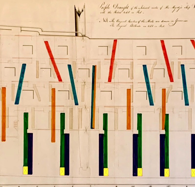
-
Iron Braces on Hanging Knee Deck Supports... HMS Victory
Morgan replied to tmj's topic in Nautical/Naval History
Hi Tom, You are fortunate in that the area around the Main Mast did not change significantly in the three phases I mentioned, there are no distinguishing features that would differentiate it from one time to another, so in many respects it is readily adaptable. This is excepting for the upper decks Riders, you have made a nice job of the lower riders, so having got these in place already this sets a date of no earlier than 1788. If you include Upper Deck Riders you can go for an authentic Trafalgar timescale, but in reality it could be anywhere from 1788 - 1814, so covering the French Revolutionary, and Napoleonic Wars. If you don’t add Upper Deck Riders then the model, with the addition of Iron Knees, which is where you started this thread, can be anywhere from 1816 up to the present day. All these periods of Victory’s long life are equally valid, although many of us, me included in particular get fixated with the Trafalgar period. Gary -
Iron Braces on Hanging Knee Deck Supports... HMS Victory
Morgan replied to tmj's topic in Nautical/Naval History
Hi Allan, I will do, I might just tease a few findings and features as well. Gary -
Iron Braces on Hanging Knee Deck Supports... HMS Victory
Morgan replied to tmj's topic in Nautical/Naval History
I wasn’t thinking of going down that route, it would be nice to recoup some costs 😏 but that isn’t where or why I started. So it will be made available here first and free. There are copyright considerations as I rely on some third party images, it’s a work of personal research and not for commercial purposes, but if it’s copied around, cited, or relied upon then usual attribution caveats will apply. I will need to give thought to how to release, whether in parts, as part of a build log (from a copyright perspective this seems right), or all in one go, but not quite there yet. It will be in PDF format. Gary -
Iron Braces on Hanging Knee Deck Supports... HMS Victory
Morgan replied to tmj's topic in Nautical/Naval History
You mean something like the attached (sample only)? c.400 pages, several hundred images, tables, etc. 9 years to research taking in the NMRN, TNA, RMG / NMM, British Library, etc. Call it Pt.1 of my Victory build log - Pt. 2 will be the actual build. I guess finished by Xmas, presently on with a late change, just looking at Victory’s bow shape which seems to have changed after 1788, trying to discern whether it was in 1803 and the pre-Trafalgar refit or whether it was the 1814 / 16 refit and I’m seeing remnants of the Round Bow, awaiting further hi-res plans from NMM. Gary Nelsons Victory Revealed Proof Sample.pdf
-
Iron Braces on Hanging Knee Deck Supports... HMS Victory
Morgan replied to tmj's topic in Nautical/Naval History
Tom, The fundamental choice in this debate is to what time period are you modelling your cross section. Longridge and McKay both show the ship in her post 1920’s restoration, this is not the same as her Trafalgar appearance, nor her 18th Century guise, or her 1816 - 1922 configuration. For post 1928 go with Longridge & McKay. For 1816 - 1922 go with the Boyne, as Allan sets out. For 1788 through to 1814, including Trafalgar, forget iron knees and go with Riders. Gary -
Iron Braces on Hanging Knee Deck Supports... HMS Victory
Morgan replied to tmj's topic in Nautical/Naval History
Iron knees and straps only went into the Victory in the 1814 / 16 refit, up until this time she was fitted with an extensive suite of timber Riders across all decks. In the aforementioned refit all Riders above the Orlop deck were removed and replaced with iron knees and straps. RMG Drawing ZAZ0122 shows these for the 1788 refit of Victory. A memo from Lt. Layman to Nelson confirms the retention of these fittings and enumerates them, they broadly tie-up with the drawing indicating continuity and retention of the Riders configuration. Gary -
Construction of Masts for 18th Century 'Ships of the Line'
Morgan replied to tmj's topic in Nautical/Naval History
And so you can associate what Allan and Gregory have posted with Victory below is an end-on view of a section of Victory’s Foremast at Trafalgar. You can make out the built-up structure. Gary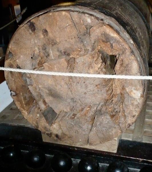
-
Thinking things through: Victorys bobstays
Morgan replied to dafi's topic in Masting, rigging and sails
My view is the same, it started as a model for the new class of 98-Gun Second Rate ships ordered by St. Vincent, to the lines of the Victory. The profiles for the Union and Boyne have this information written upon them. This explains the different gunport disposition. At some point the model of the Boyne / Union was changed to commemorate the Victory and Trafalgar. New models for altered ships are rare, although not unknown, although this is usually to demonstrate some novel feature, Victory had none of these in her 1801/03 refit, so why a new model for a run of the mill refit? A lot of the apparent affection for Victory was to come later, and contrary to myth Nelson did not request her nor did he guide her refit, she was destined for the Channel Fleet under Cornwallis unless Cornwallis were to allow Nelson to keep her. In spring 1803 Nelson had to leave Victory and proceed to the Mediterranean without her pending Cornwallis’s approval. Two of the main features different between the model and Victory are the rearmost lower gunport missing on the model and the stern, which Allan has posted above. Both Goodwin and Lavery have said that the closing-in of the gunport and stern were future developments planned for Victory which had to be cut short to rush her out for service. This nice explanation tidies things up, but is wrong. Victory was not being rushed into service, in 1802 and early 1803 the Chatham Officers were asking if she was to be readied for sea or placed into Ordinary, there was no urgency to get her commissioned. The team refitting her were saying we are nearly done here, what would you like for us to do with her! I have copies of letters from TNA that were exchanged. And why, if the ship was being rushed for service, would you plan for the stern shown above, but because of time constraints you instead short-cut it and produce the stern we all know, which was in place at Trafalgar (we have strictly contemporary sketches from Turner and Livesay to support this). It makes no sense, especially as we know the ship wasn’t being rushed. Another anomaly, the figurehead, which is that of the Victory, it is in a starkly contrasting colour, it looks like a latter addition, as do some of the clunky stern decorations. LG Carr Laughton, who researched the Victory for her 1920 restoration actually dates the model to 1803, and not 1805 as stated by the NMM. But, in either case, how did the model get its Nelsonic paint scheme? When re-launched in 1803 she didn’t have the Nelson chequer, the painter Constable tells us this, she had fewer broader stripes. This, in my view adds to the thought of the model being altered to commemorate the Victory, but it started out as a model for the new Second Rate class. As for the name on the counter, Victory didn’t have this at Trafalgar, again this is evident from the Turner and Livesay sketches, the name on the counter is to tell the observer which ship the model is and is not an actual recording of ship’s appearance. And the NMM just paid north of £500k for this model! Gary -
Thinking things through: Victorys bobstays
Morgan replied to dafi's topic in Masting, rigging and sails
If only it were so straight forward! On the lower and middle deck the bridle ports are not routinely armed, and on the middle deck there is the issue of whether an entry port is fitted! Carronades were not counted as guns in the RN until after the Napoleonic Wars, but ports are provided for them. Carronades were normally additional to the long gun count, but could also replace them, but this reduction or substitution in long guns would not affect the rating! Confused? That’s why after Napoleon was ‘put to bed’ the system was simplified and all ordnance counted towards a ships rating. The hull forms meant that First and Second Rates were essentially interchangeable and many 98-gun Second Rates would later be re-rated as First Rates. Whilst notionally the scantlings separated a First and Second Rate as the classes grew the boundaries blurred between the 98 and 100 gunner with ships moving up and down the ratings from time to time. During the Napoleonic Wars Second Rates normally had only 14 32-Pounders on the Lower Gundeck, as opposed to the 15 (and later 16 of larger) First Rates, discounting the bridle port the model and plans referred to above agree on this. On the Middle Gundeck a Second Rate carried 18 Pounders as opposed to the 24 Pounders of a First Rate. Victory was reduced to a Second Rate in 1808 and had 18’s in lieu of 24’s, and lost a 32 Pounder. The balance of long guns were made up of 12 Pounders, usually 30 long 12’s on the Upper Deck, and 2 long 12’s on the Forecastle (later the Forecastle 12’s became medium length 12’s), and the balance on the Quarterdeck which had enough ports to accommodate the balancing number, these were usually short 12’s. So the difference between a First and Second Rate came down to the ordnance establishments - number and weight, and not the hull form. Gary -
Thinking things through: Victorys bobstays
Morgan replied to dafi's topic in Masting, rigging and sails
Daniel, The only one with any provenance is the 1805 model. The present day ship is a chimera of designs and times (or designs out of time!), and the Longridge example - whatever it is, is appears to be no better. Like you I think the 1805 Model is Boyne / Union, a 98-Gun half sister to Victory, but that is irrelevant to your query, the rigging points are applicable whether a frigate or first rate, si I would follow what the model offers. Gary -
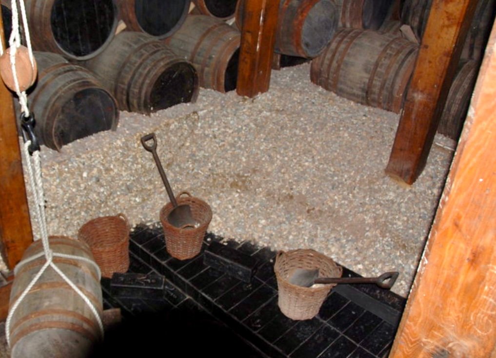
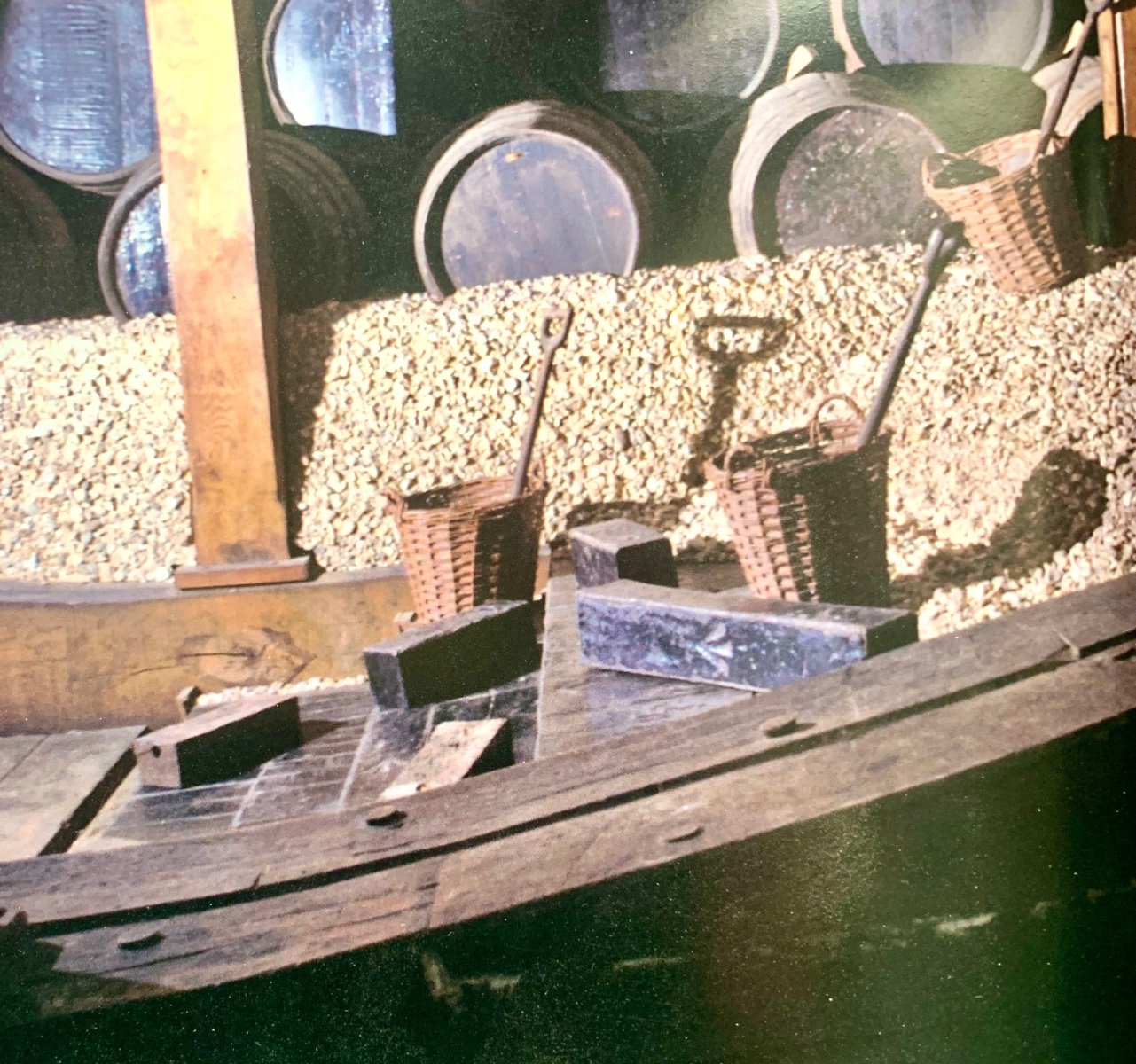
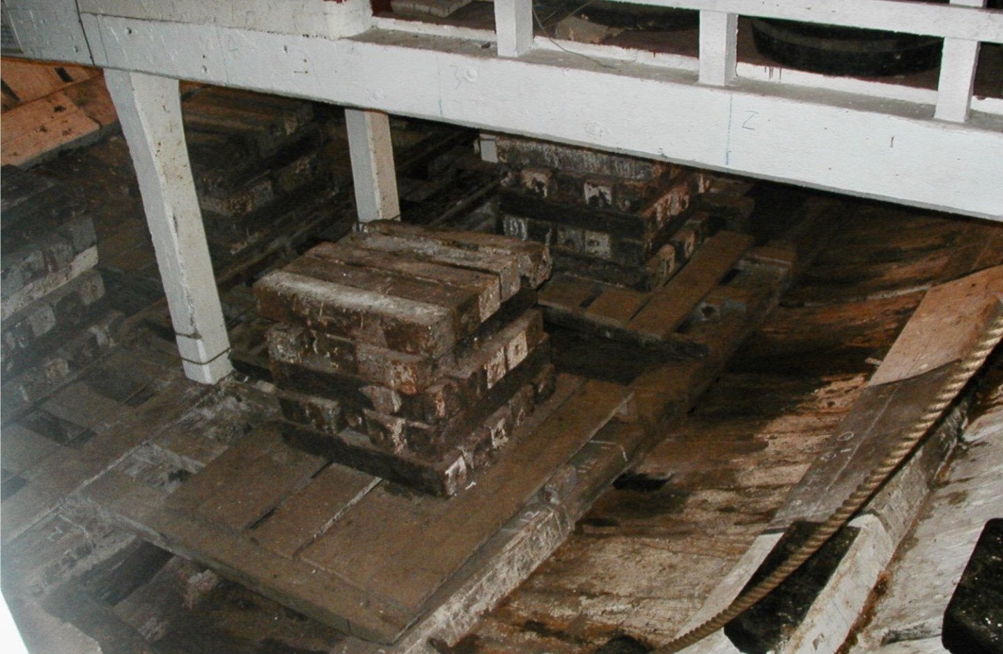
Hi Tom, Here is another angle on the photo I posted above. You can clearly see the random pig ballast, very similar to what Allan posted above, but also of smaller or half size pieces. They are actually sat on a whole stacked set of cast ballast if you look close enough. Gary

-
The Victory’s primary ballast by 1805, assuming you are modelling the Trafalgar Victory, consisted of ‘Pigs’ of iron. These large ingots were overlain with gravel or shingle, although this added to the ballast weight it’s primary use was to provide a stable bed for the lower tier of casks and stop them rolling around. I don’t think stones would be accurate. Gary