HOLIDAY DONATION DRIVE - SUPPORT MSW - DO YOUR PART TO KEEP THIS GREAT FORUM GOING! (Only 27 donations so far out of 49,000 members - C'mon guys!)
×

Morgan
-
Posts
546 -
Joined
-
Last visited
Content Type
Profiles
Forums
Gallery
Events
Everything posted by Morgan
-
 One of the other sets of prints, the frigates, looks sort of Indefatigable style to me if I’m not mistaken. Gary
 -
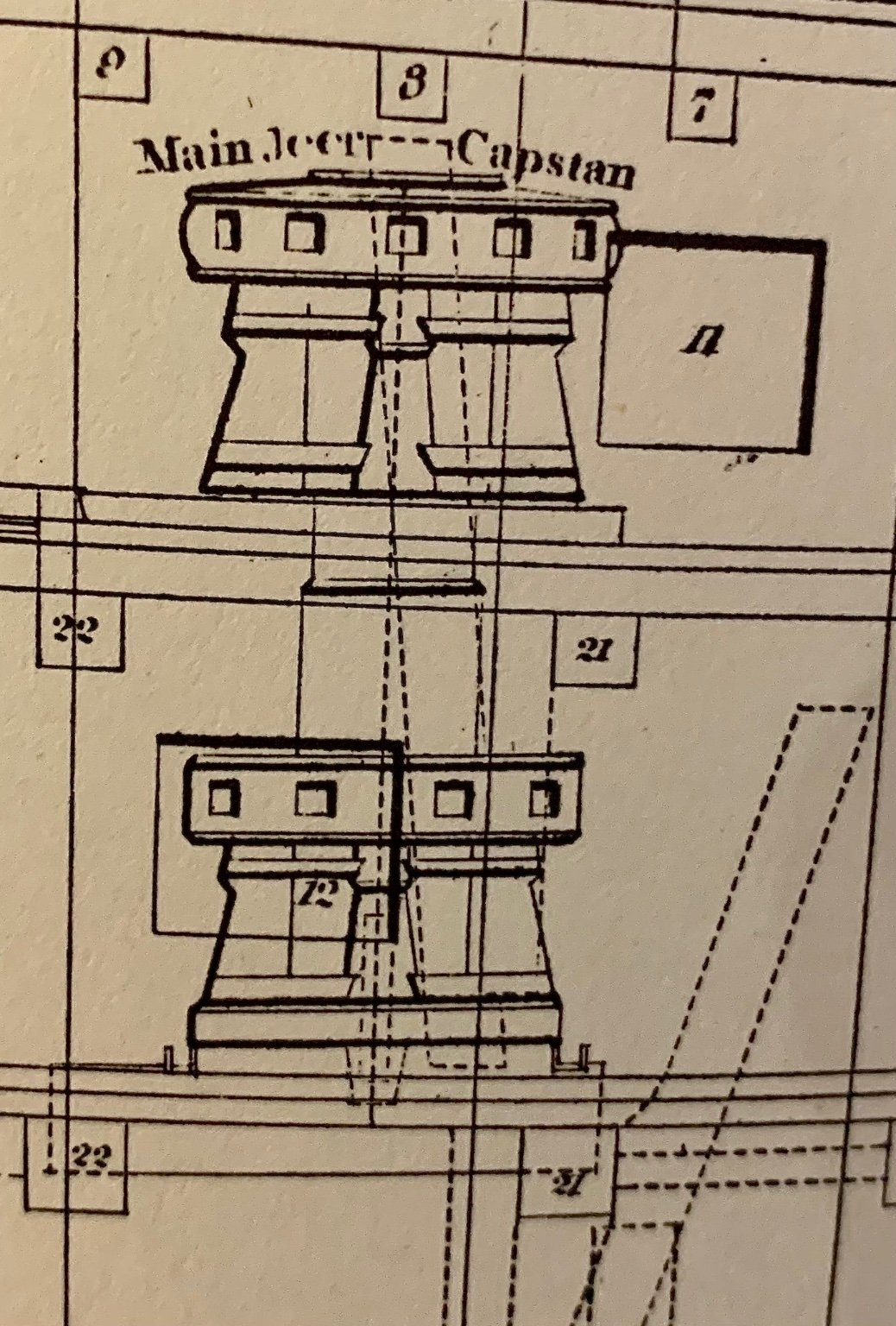
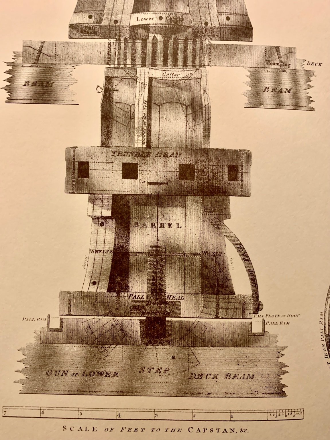
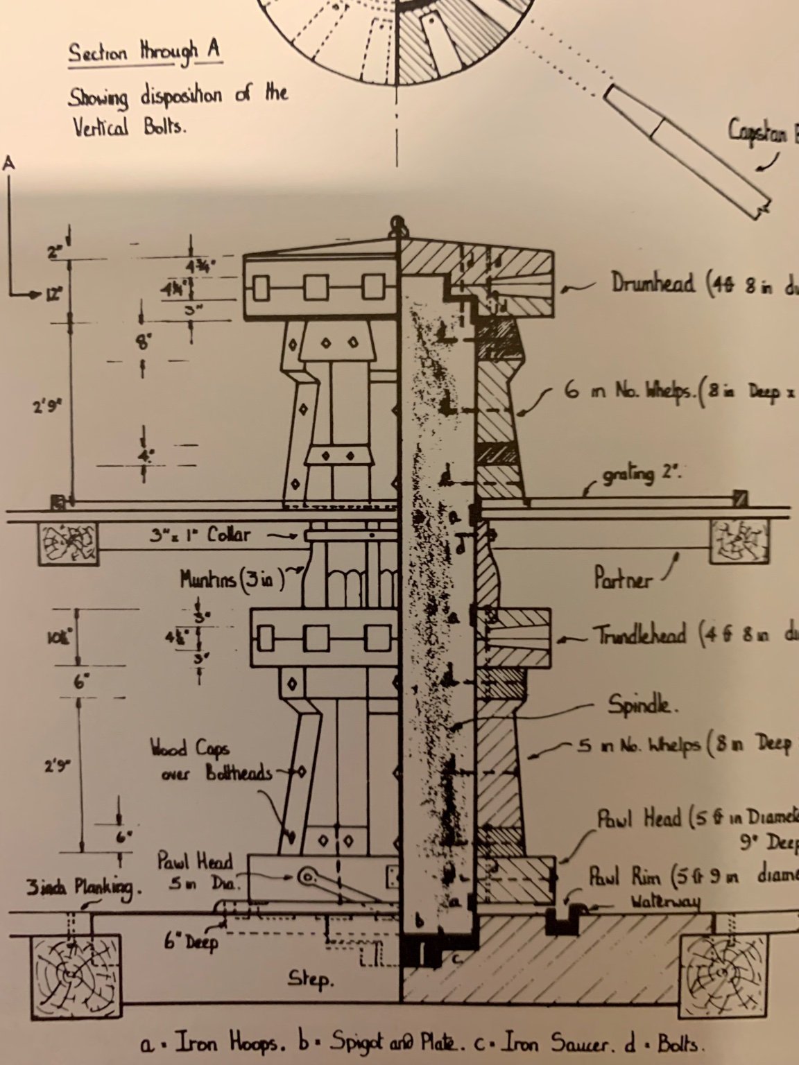
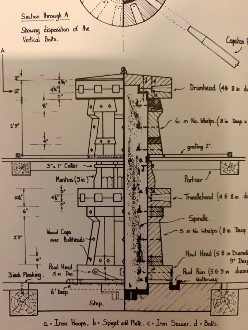
Daniel, I think it is a cover for the Capstan Channel / Waterway. Looking at the inboard profiles for Steel and Rees the lower main capstan has the pawl rim or channel around it, but not to the fore lower or upper capstans (photos below). I recall that Capstan uses changed in the second half of the 18th Century, so the fact that you get the cover on either the fore or main capstan probably depends on practices in place at that time. Goodwin in his ‘The Construction and Fitting of the Sailing Man of War 1650 - 1850’ provides a comparative cross section at page 148 where you can see the cover to the left hand side, and is labelled waterway to the right hand side. Gary


-
I’ve seen both, like a lot of English rhyming slang there is usually a progression that ends up with you racking your brain as to how they got there.
-
‘Ham n Eggs’ rasee sister!
-
Following a recent visit to the NMM Greenwich I can also confirm that Turner’s The Battle of Trafalgar shows the Garter Star to the Cathead. It is a huge painting and you can get within a few feet - closer if you lean in 🙄 Turner is the only artist that captured Victory after her return from Trafalgar, there is an extraordinary treasure trove of detailed sketches at the Tate. Interestingly he also shows 4 rows of glass panes to each of the windows of the quarter gallery, a feature he also captures in relation to the stern windows in his watercolour From Quarterdeck to Poop. Gary
-
That a lower studding sail boom, not a spare yard. Gary
-
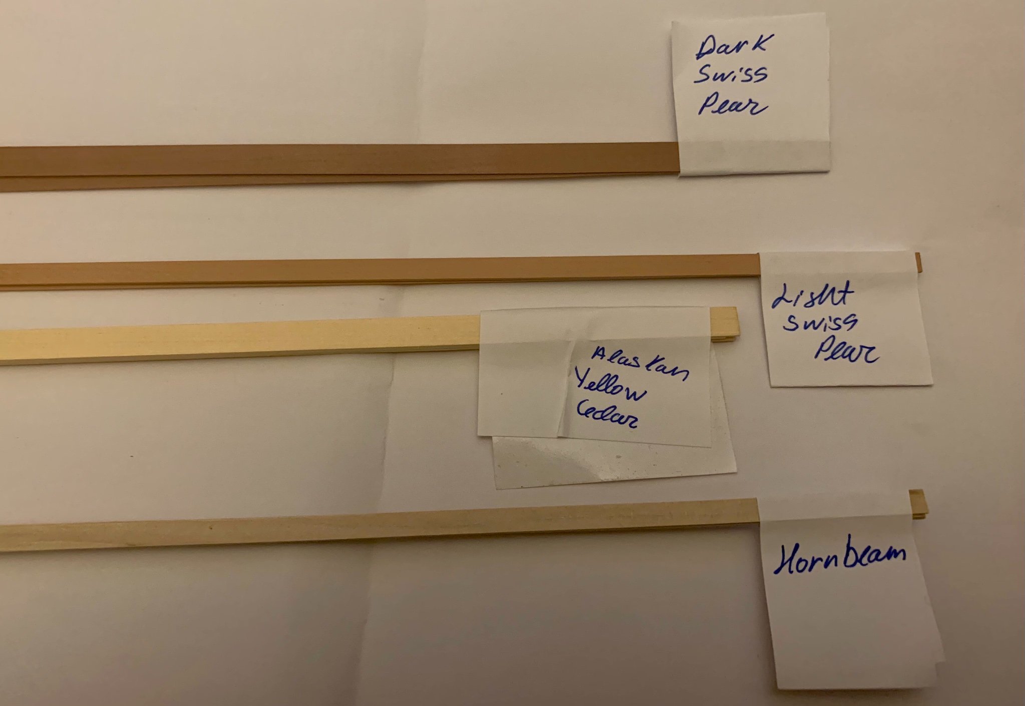
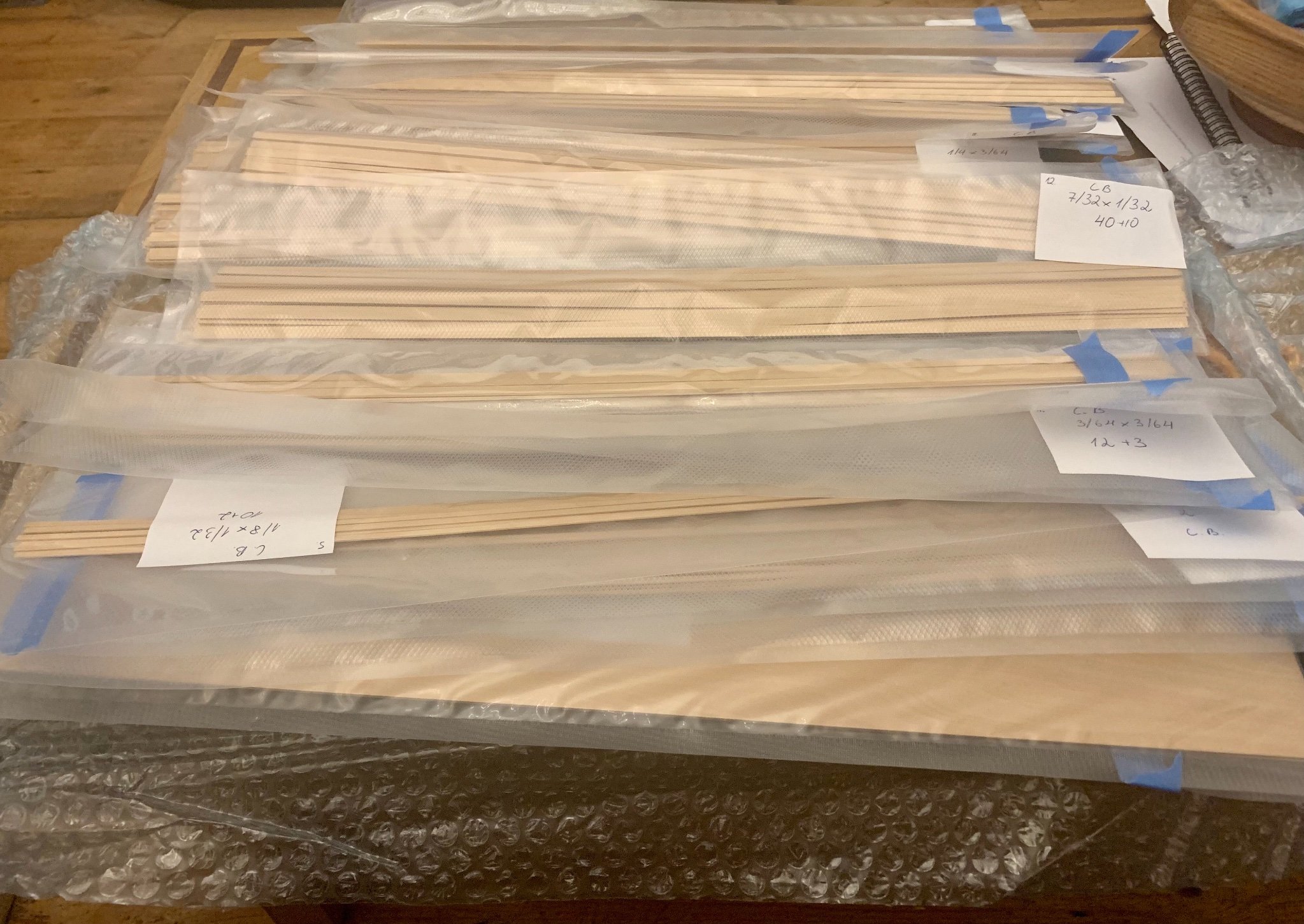
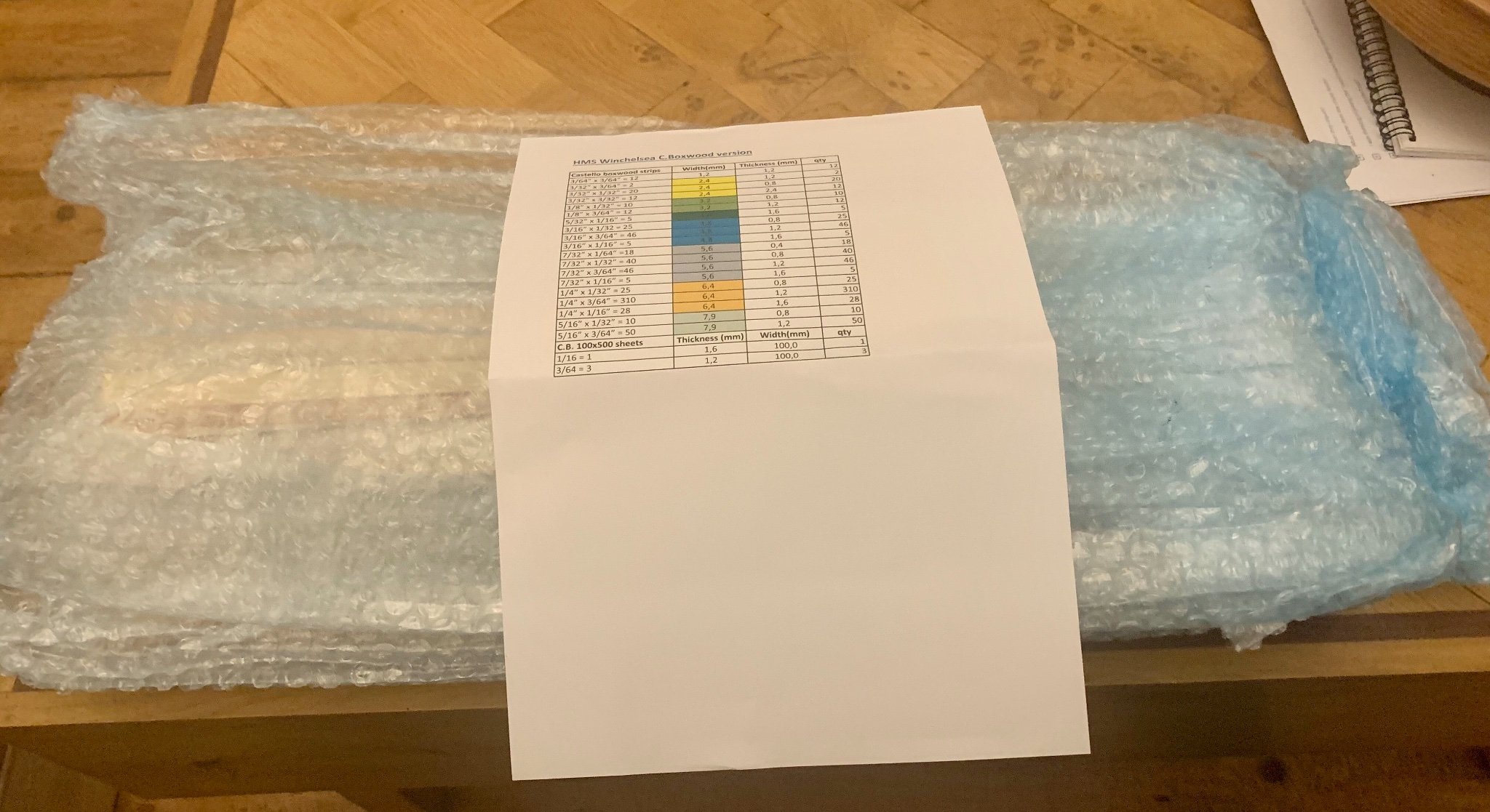
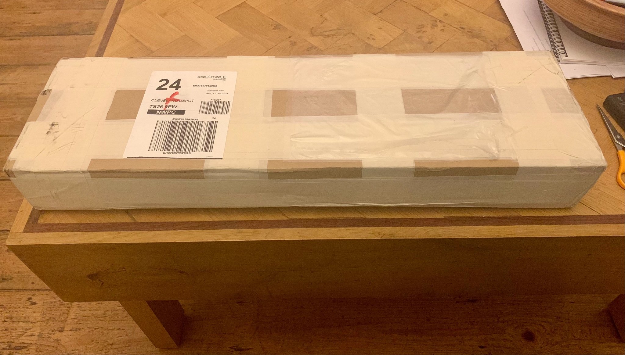
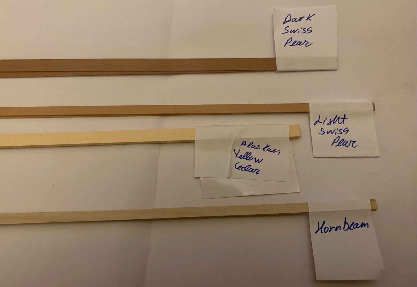
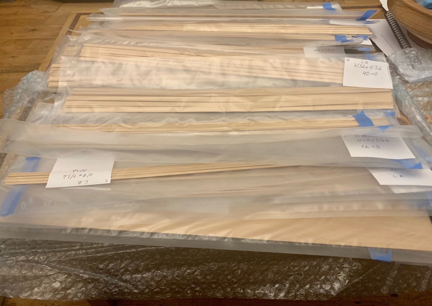
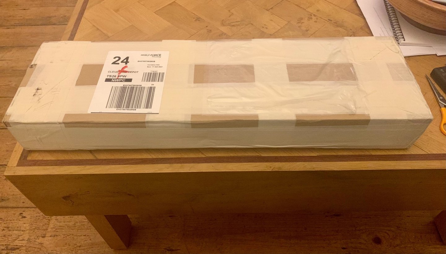
Earlier today I took receipt of a nice package of wood from Vahur of Hobbymill.EU. I’d ordered the timber set for Chuck’s Winchelsea. I have plenty of English Box to mill, but not the time to mill it at present, that stops me moving forward. So I decided to try Hobbymill, and must say I’m pleased to have done so. The timber is well colour matched, and extremely well milled with an excellent finish, nice crisp and clean, as good if not better than the the veneer strips I often buy. Definitely a fan and will be buying from Hobbymill again. The Winchelsea cutting list produces a large bundle of wood. It comes well packaged, and is well marked. Having emptied the box I can’t get it all back in again. Vahur also provides some samples of other wood just to tease. Photos attached. Gary

- 75 replies
-
- 10
-

-

-
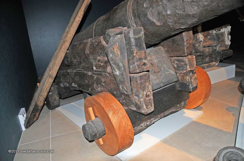
On these you can see the cleat, and possibly a decayed horn to the front.
-
Daniel, Also looks like a metal hoop fitted over the end of the axle, it wasn’t to retain the wheel as we can see the socket for the pin. I assume it is merely to strengthen the axle at its narrowest point to stop it splitting. Gary
-
Daniel, One thought is that the cleats and horns were made of soft wood and were of a sacrificial nature and regularly replaced as these took the bulk of the wear and tear. Another is that they were fitted by the carpenter and that the carriages were supplied without them. They could have been painted red, to be honest I haven’t seen anything on paint analysis, the publications available haven’t addressed the carriages. Gary
-
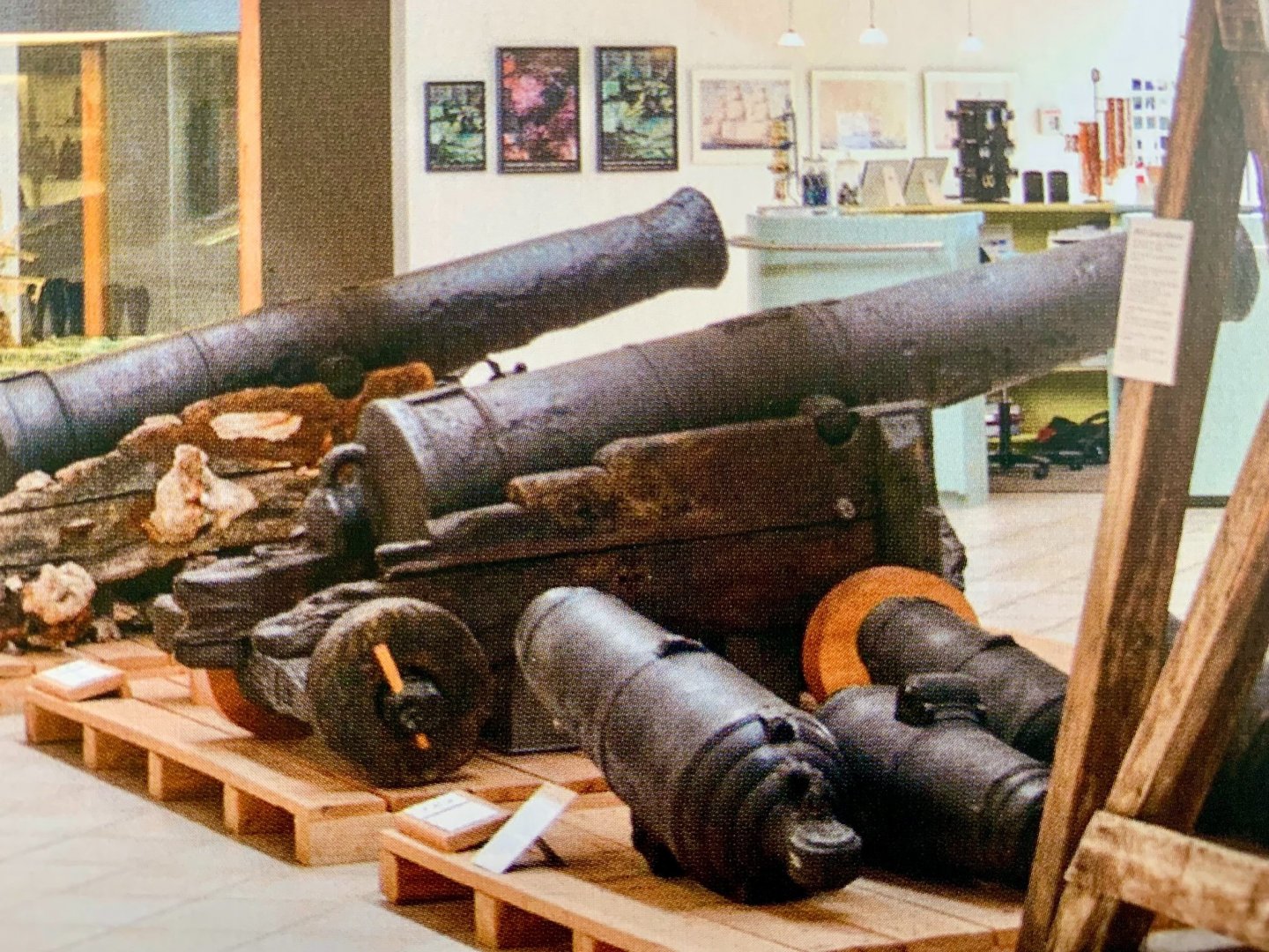
One issue with the Victory gun carriages is that when reconstructed in the 1920’s (and earlier) the carriages used as a template were fort carriages. You will see in many earlier photos the guns do not sit central to the gunports. This issue was identified by Peter Goodwin. The carriages have been modified to rectify the centring of the guns, but those rear eyebolts persist. The St. George carriages Dafi points to are strictly contemporary with Victory in 1805, the St. George being refitted almost immediately after Victory. You will also note the positioning of the eyes on the carriage cheek are not as represented on many models. Some of these St. George carriages retain the side cleats, and also have evidence of fitting points for frontal horns which acted as a ‘stand-off’ from the ships side. Gary
-
Incorporation of fishes
Morgan replied to DaveBaxt's topic in Building, Framing, Planking and plating a ships hull and deck
Dave, That would work, I’d just slightly round-over the inside edge by sanding rather than leave an angular edge. In respect if any scarphs part of the waterway in reality sits under the side planking so you would not see a full scarph. This could make things easier to simulate if you go down that route. Gary -
Incorporation of fishes
Morgan replied to DaveBaxt's topic in Building, Framing, Planking and plating a ships hull and deck
Dave, I see you are also in the NE, a trip to the Trincomalee at Hartlepool could provide you with a wealth of information on Waterways and many other aspects. Also the Pannet Park Museum and Captain Cook Museum at Whitby both have a wealth of model ships and related artefacts, many of which are period specific for the Endevour. Not to mention the the Captain Cook and Staithes Heritage Centre / Museum at Staiths. Gary -
Incorporation of fishes
Morgan replied to DaveBaxt's topic in Building, Framing, Planking and plating a ships hull and deck
The picture provided by Spyglass is a good example of the tapering and curving of the planks that Druxy mentioned, ignore the inner margin plank and joggling or cutting-in of the planks. On the Endeavour these would have been straight butt joints between the deck planks and the darker waterway. Gary -
Incorporation of fishes
Morgan replied to DaveBaxt's topic in Building, Framing, Planking and plating a ships hull and deck
Dave, The Waterway followed the ships side in a continuous fashion, so is the only ‘plank’ to follow the run circumferentially of those sides as it were, as a regular margin feature. Traditionally the joints were scarphed together. They did not run across the stern or transom. Personally I would work from the bow to the stern. To obtain the profile they may best be cut from a sheet as opposed to strip wood if available. On the Victory for reference they are 12” wide, but I would expect Endeavour to be narrower. As a guide Victory’s main historic deck planking is 10” wide, that is 4mm @ 1:64. Also for note the outermost 2 planks on each side of Victory these wider at 12” wide (5mm @ 1:64) which helps with the run-out of the planks. Hopefully these measurements will allow you to work out dimensions relative to what the kit materials provide you with. Gary -
Incorporation of fishes
Morgan replied to DaveBaxt's topic in Building, Framing, Planking and plating a ships hull and deck
The waterway is a shaped plank that follows the bulwark as you say. In practice it was a heavier timber in section than the deck planks, and profiled not only to meet the deck planks, but also to marry up to the inner side planking, both above and below. It would be slightly raised in comparison to the deck planks and transition down at the edge to meet the deck planks, at anything smaller than 1:48 you would not notice it being thicker. The purpose, in part, was to channel water to the scuppers rather than let it get into the ships side timbers. Gary -
Incorporation of fishes
Morgan replied to DaveBaxt's topic in Building, Framing, Planking and plating a ships hull and deck
Dave, There is no evidence of this on the surviving historic ships in the UK. I’ve looked at the remaining original decks of Victory, Trincomalee and Unicorn and they do not ‘joggle’ in to the margin planks. They simply run-out and are butted against the waterway / margin plank at whatever angle they intersect it. The use of fishes was used later in the 19th Century, however some modellers do this for aesthetic purposes. In my view it would be inaccurate, and given the Endeavour was a collier it is unlikely they would have spent the time and effort. It is of course your choice. Gary -
They are flag lockers and would have had a canvas front. Gary
-
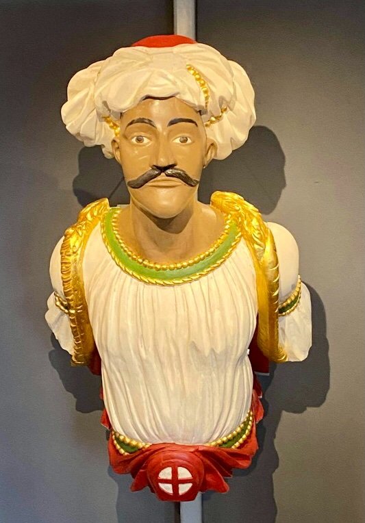
This one from HMS Trincomalee caught my eye as I attended a talk by the Curator of the ship on Wednesday. Turns out this old photo is of the ships second figurehead which dates from 1845. It has just been recently restored and is now on display at the NMRN Hartlepool, see below. The colours are slightly different from the ship copy as research during restoration facilitated the analysis of old paint samples. Gary
-
I’ve got an original 1806 copy, the book is tiny, about 4” square! Going price right now is about £300 from antiquarian book sellers, it’s part of the long term pension investment, or at least that’s what I tell the Admiral! Gary
- 1 reply
-
- 5
-

-
-
Plenty big enough for the Royal George you have been thinking off 😉 I was at the NMM Greenwich today and she is currently on display in the Nelson, Navy and Nation exhibit, unfortunately against a wall so you don’t see the planked side, but still a beautiful model. Gary
-
And then there was only 1 left! Just ordered the second but last, no fighting over the last one 🙂
-
The additional structure could possibly be an opening for ventilation above the stove, the immediate proximity to the chimney could make it a steam scuttle. Gary
-
What scale are you building to James? I’ll pop in from time to time to see how you are doing. Gary