HOLIDAY DONATION DRIVE - SUPPORT MSW - DO YOUR PART TO KEEP THIS GREAT FORUM GOING! (Only 36 donations so far out of 49,000 members - C'mon guys!)
×

Morgan
-
Posts
546 -
Joined
-
Last visited
Content Type
Profiles
Forums
Gallery
Events
Everything posted by Morgan
-
There is circumstantial evidence that Victory carried crows feet at Trafalgar. The painter Clarkson Stanfield when preparing his ‘Trafalgar’ painting produced a first draft for comment. The commentators in question were Trafalgar veterans including Victory’s captain Hardy. This initial draught showed no crows feet, but the final version included them. This obvious change suggests that this was a correction made on input from those veterans and points to a strong possibility of Victory having them fitted at Trafalgar. Gary
-
 Any chance of adding 1:72 to the boat line-up to compliment some of your legacy kits from your earlier career 😁 Gary
 -
To add to Chris’s point, ships carrying less than 20 guns were ‘un-rated’ and not impacted by the guns -v- carronades -v- total ordnance argument that muddied the rated ship system delineations prior to a total ordnance rating system adopted in 1817. Gary
-
👂👂18th! care to drop any further hints 🫣
-
I’ll follow along, I’ve got this to start at some point and it’s useful to have more than just the YouTube videos to reference. Gary
- 32 replies
-
- 1
-

-
- Victory
- Artesania Latina
- (and 1 more)
-
Dimension ‘A’ in Post #2 or ‘step’ between the Wales and the planking above and below were not that great, they would only be one to two inches (25 - 50mm). On Victory the Black Strakes, those planks above the Main Wale were two inches thinner, as were the Diminishing Strakes, those below the Main Wale, and so on. The higher up the ship the less noticeable the change in thickness with the subsequent strakes and Wales. At a maximum of 50mm difference step change in planking in the scales we generally work at we are talking only 0.5 - 1mm difference, or Dimension ‘A’ in post #2 above. Gary
-
Incredible Orkney Shipwreck https://www.bbc.co.uk/news/articles/crg447y13nzo
- 6 replies
-
- 12
-

-
-
You’ve mentioned before this is an itch you want to scratch, just go for it 😉 Gary
-
The reasoning for ‘Top down’ and ‘Stern to Bow’ is to negate the effect of friction on the plating. Consider the impact of friction as the ship moves through the water, this was enough to wear down the copper plating over time. The same forces will act on the seams of the copper plates. Forward facing seams would be more prone to opening up as friction has each individual seam to act upon. A rear facing seam allows the water to slip over the seam with a much reduced impact. The same applies with the horizontal seams, the effect of water on the ships hull is to constantly push it upwards, hence the seams were also upwards facing to mitigate this frictional force that would otherwise work its way much easier into those seams. Gary
-
This is certainly what Bugler says of Victory: ”The sheets were worked with laps, clinker fashion down, and butts, clinker fashion, aft. The strakes were run as far as practicable parallel to the waterline. At the fore end they were laid roughly parallel to the fore foot.” My reading is ‘Top Down’ and ‘Stern to Bow’ as the lay direction. Gary
-
Two points to consider. Firstly, drawings are not definitive when it comes to fixtures and fittings. And secondly, the contract only takes the ship to the point of handover to (usually) a Royal Dockyard for fitting out, tiles could be added during fit-out, the silence in the contract or drawings does not preclude this. I assume the addition of the stove itself was by the navy at the appointed Royal dockyard and not by the Contractor? Gary
-
Ships at Trafalgar - what kits are available?
Morgan replied to bruce d's topic in Wood ship model kits
Her sisters, Neptune & Dreadnaught were also at Trafalgar, so 3 for the price of one option. Gary -
I may even be able to tell you what pattern of gun went in which port where a deck had a mixed armament 😉
-
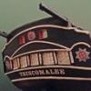
Hi cbill, In answer to your question, certainly as late as the Napoleonic wars First Rates carried swivel guns. There is strictly contemporary evidence of Victory having 3 swivel guns mounted on a rail at the break of the Poop Deck at Trafalgar, as evidenced by a watercolour made by JMW Turner in December 1805 (see below). This was somewhat unusual as they were normally mounted in the fighting tops, but Nelson did not like small arms fire in close proximity to the sails. In this instance it had been shot away during the battle but was subsequently reinstated at Gibraltar during temporary refitting. Although not First Rates there is also evidence of swivels at this time being mounted on capstans for example, so it seems almost any convenient place. Please do take the time out to introduce yourself in the ‘New Member Introductions’ section, and welcome to MSW. Gary
-
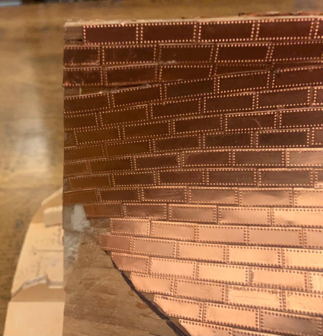
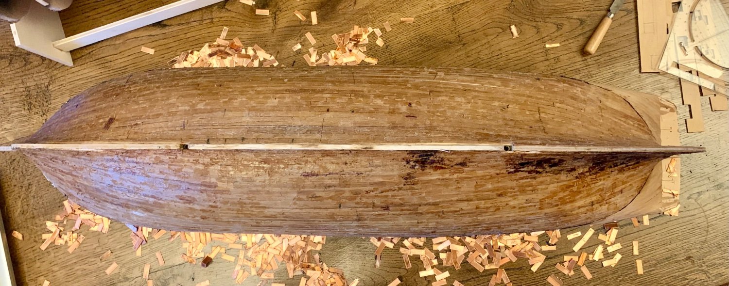
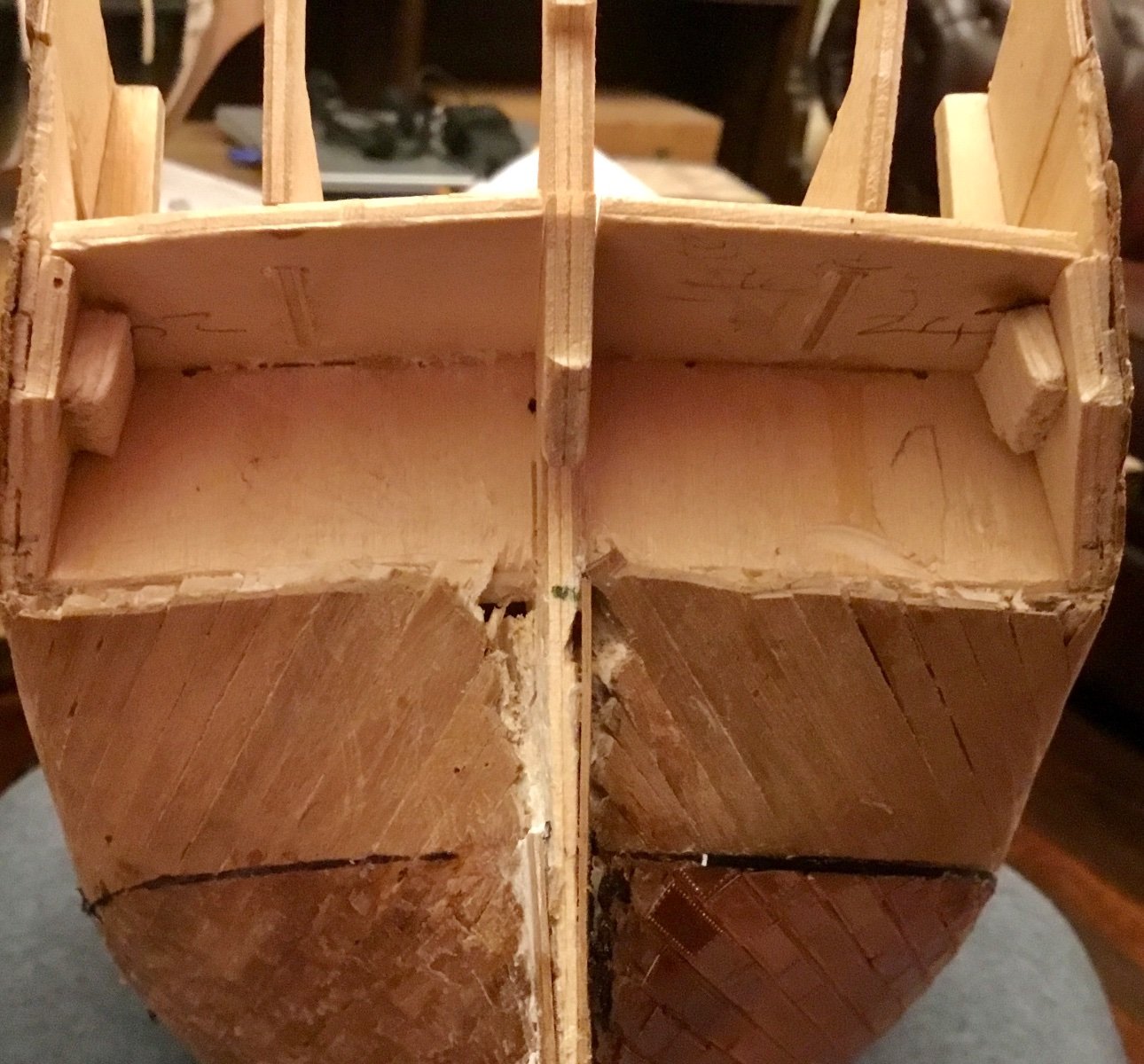
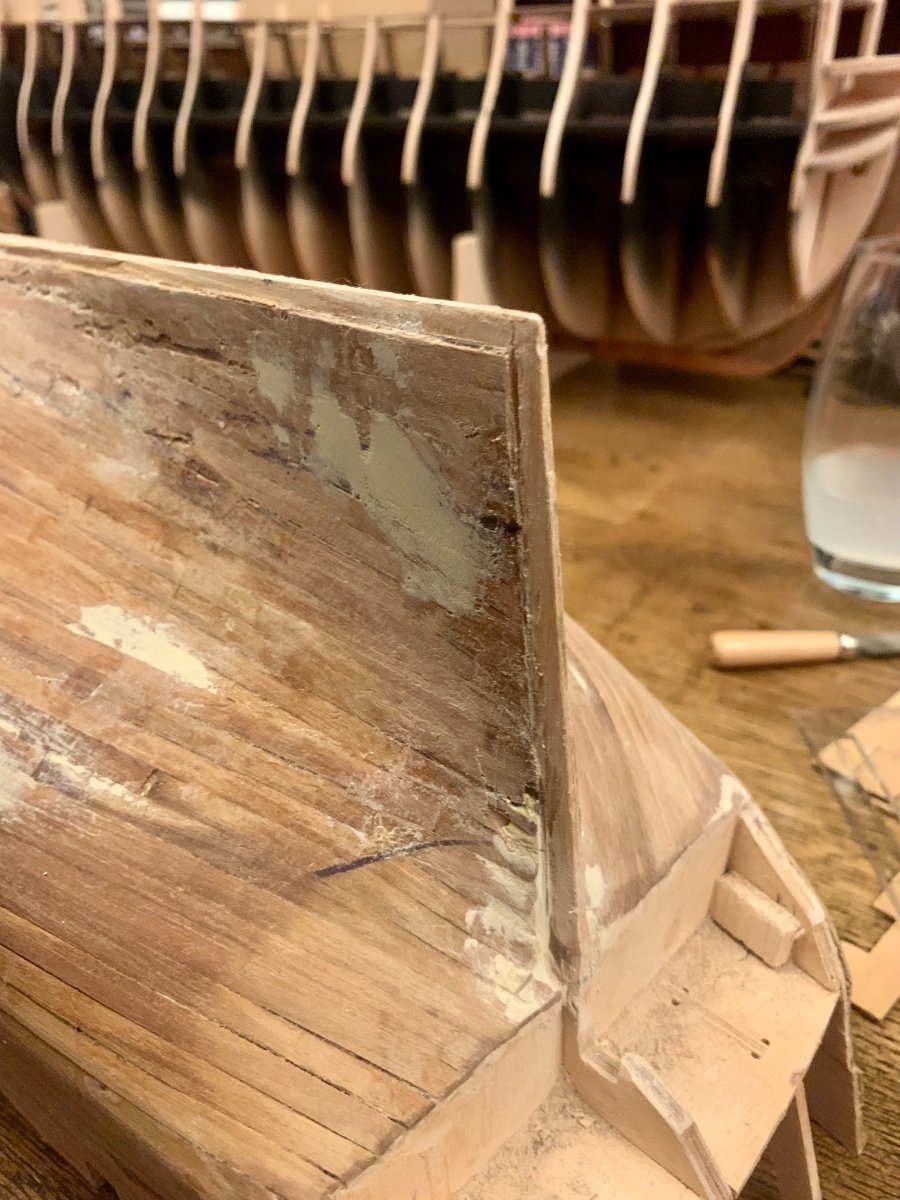
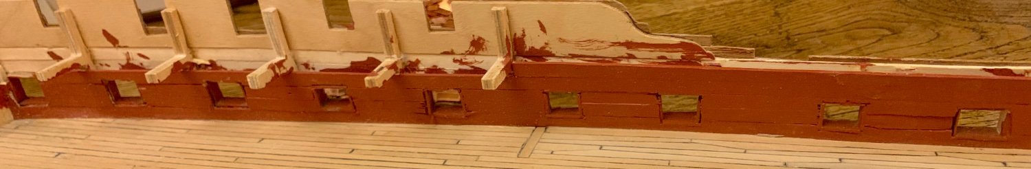
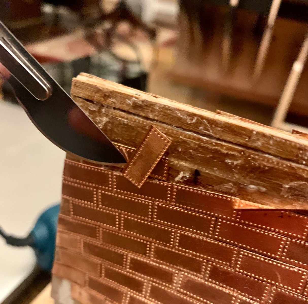
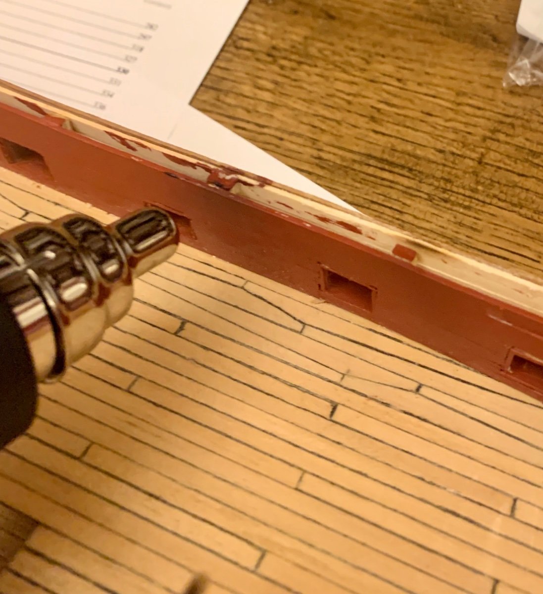
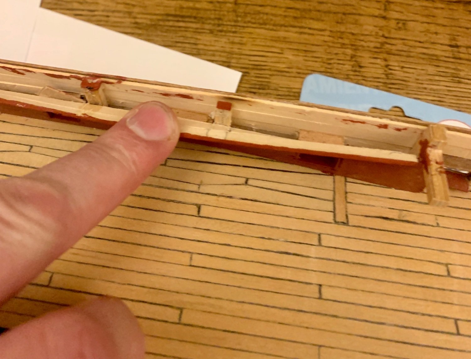
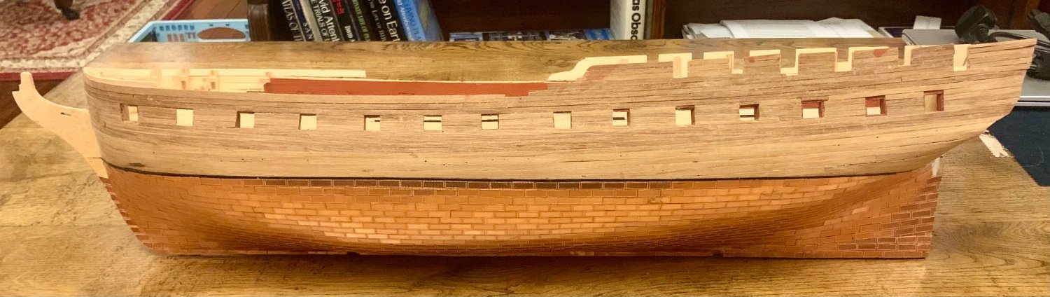
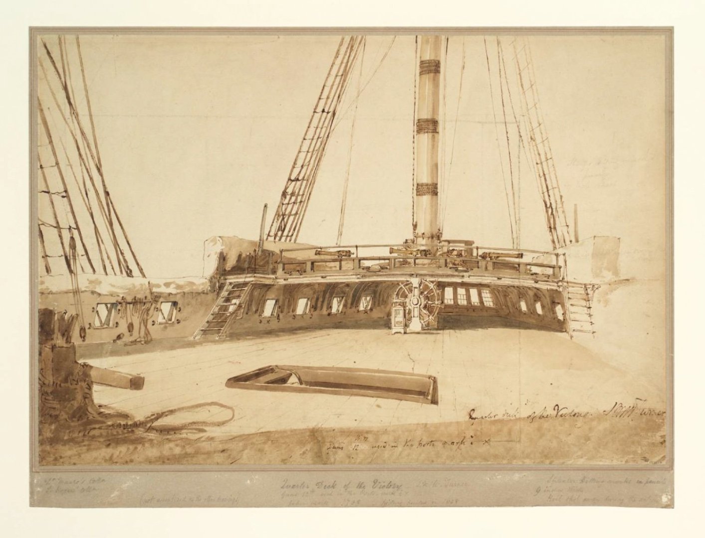
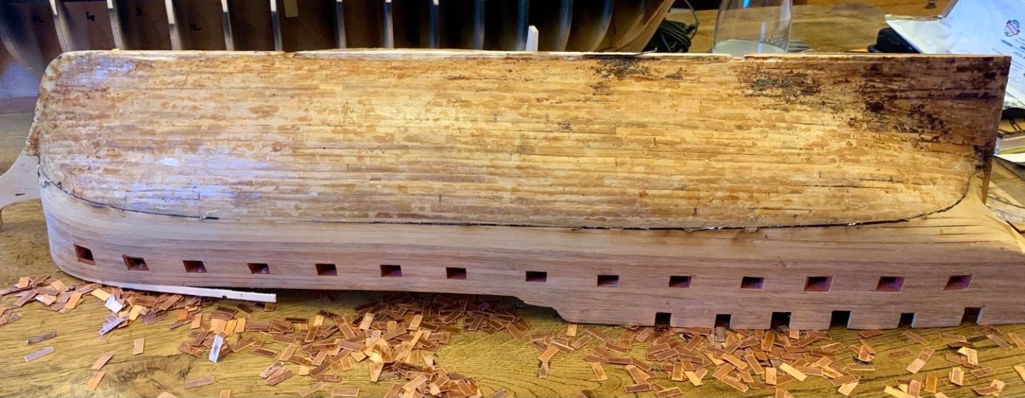
The removal of the copper plates has continued, leaving the glue residue to clean up. The heat from the removal process has left the glue residue brittle, making sanding removal fairly easy. The exposed hull leaves a couple of areas to address, also, the keel needs squaring off, it has lost its profile, I’ll add a false keel and fill up to this line and sand it back. The re-coppering will hide this. More of a problem is an area of planking that falls short of the sternpost under the counter, for now this is filled and sanded, but I have to address a more permanent solution. One possibility is to paint the hull below the Wales. As identified earlier the gunports needed realignment. The only way to do this is to remove them, but this necessitated removal of all internal and external planking down to deck level, so another case of moving backwards before continuing. The removal of the planking inevitability damaged some more of the upper extensions frames of the bulkheads. However, having stripped the hull back I can now been able to move forward with reconstruction. I have put in place some gunport framing and ‘splints’ to support the original structure and re-establish the profile ready for re-planking. None of this will be visible and is only to hang the planking on and for lining the gunports. It necessarily has to fit in with and between what is in place, which means it fits where it touches, but ‘pretty’ isn’t a consideration. There is some more fettling and levelling required. To aid this the lower plank of the inner bulwarks have been cut to the same height as the sills of the gunport frames, this is not yet glued in place as this will allow each port to be aligned / squared prior to fixing down. When positioning the inner bulwark lower plank the longitudinal ripple along the deck is obvious, but once a waterway is fixed this will obscure it, it won’t affect the cannon placement as it is limited to the outside of the deck, and most will be obscured by the weather decks. It seems that where the deck is not supported by the transverse bulkheads there is a tendency in places to have sunk, but no matter, onwards and upwards. Gary


-
Axminster 300 mm disc sander unboxing
Morgan replied to vaddoc's topic in Modeling tools and Workshop Equipment
Hi Vaddoc, I doubt you’ll go wrong with your sander. Axminster customer service is excellent, ans are their products. As a specialised woodworking supplier they know their business and what customers want from them. The Admiral has to place time limits on my store browsing when I visit, I could spend all day in there. Gary -
I would search for the likes of the commanders such as Howard of Effingham, Sir Francis Drake, Sir Walter Raleigh, or other commanders of the era. Include the names of their ships in the search as well, it may help narrow the search. I can’t guarantee you will find what you are looking for but it is as good a starting point as any, hopefully other here can suggest other contemporary sources. Good luck with the search. Gary
-
Have you tried studying paintings of sea officers from that era, I would imagine some would show themselves in their cabins which may also capture how the cabin is furnished. I certainly recall that such images from some of the leading figures of the Spanish Armada (on the Spanish side) are so painted (I can’t recall where) but possibly some may also exist of English officers. Bit of a long shot but they would certainly be contemporary. Gary
-
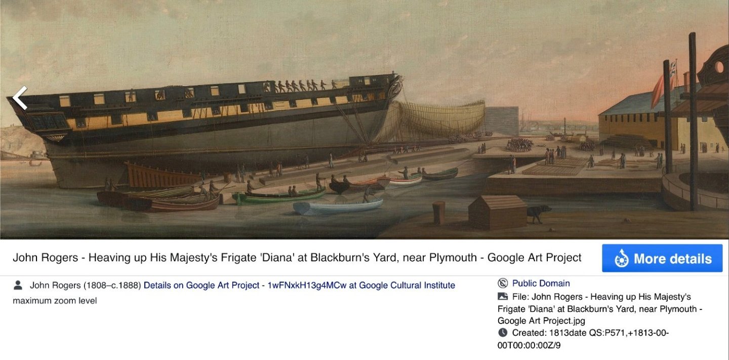
Hi Sizzolo, Just a heads up, in 1806 Diana would have carried a built-up forecatle this was an Admiralty directive (I can dig out the reference), she still carried this in 1813 as per the photo below. Not as aesthetically pleasing in my view. Also note 8 QD ports. Obviously your build and decisions, just adds to the mix of info. Glad your National Archives visits are finally bearing fruit. Gary
-
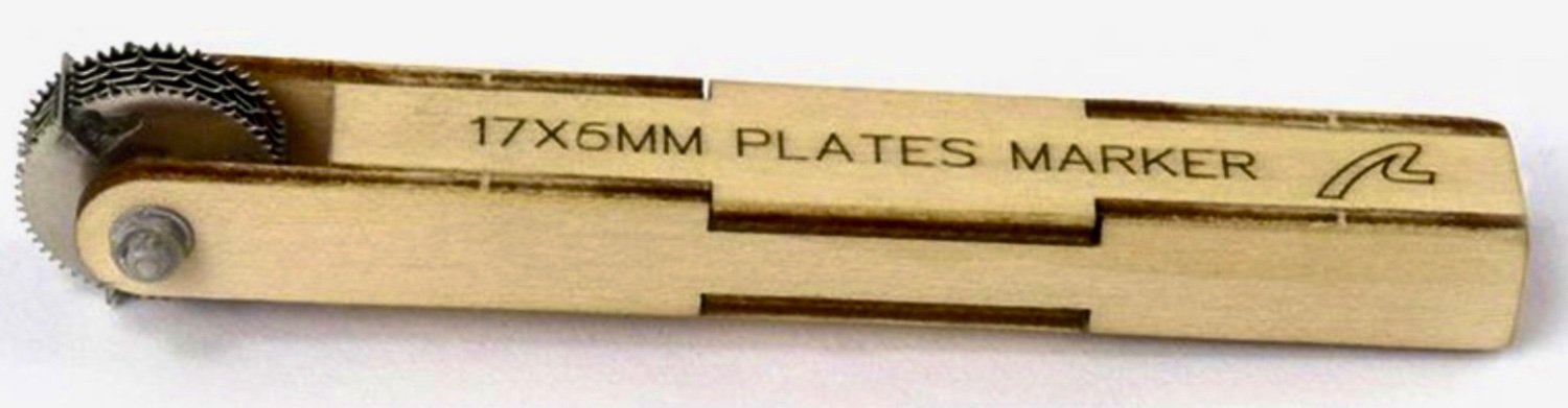
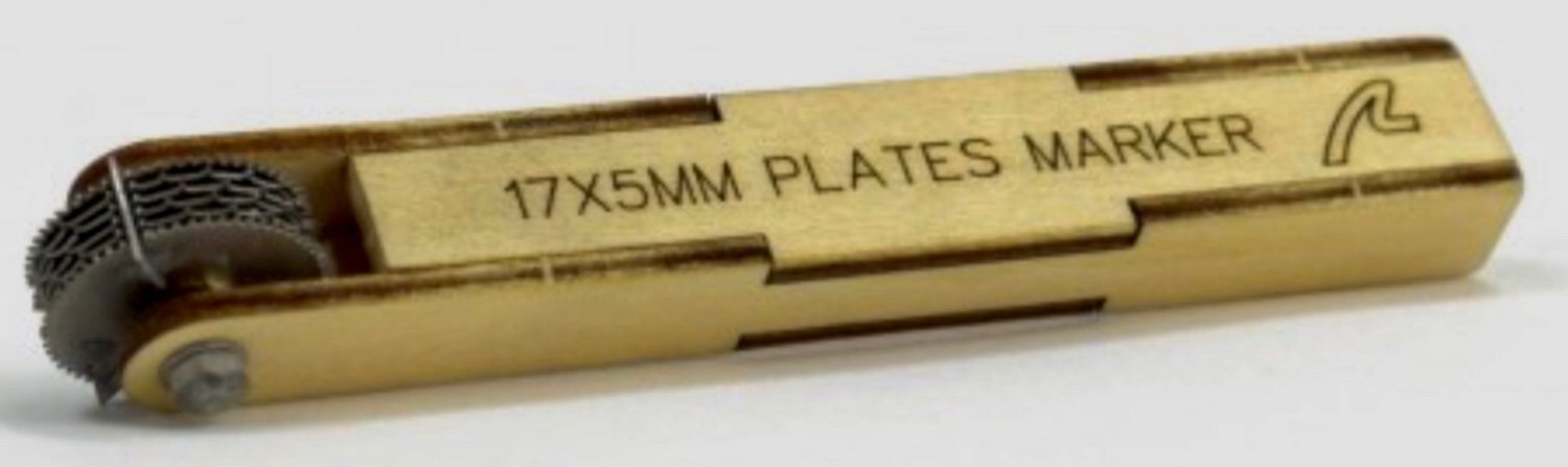
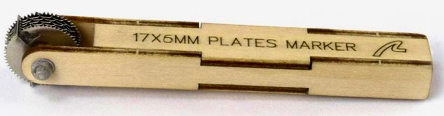
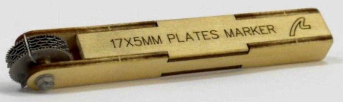
If you account for the overlap the effective plate size is 46.5” x 13.5”, at a scale of 1:72 and converting to metric then 16.4mm x 4.8mm, so the 16 x 5 AL version works, so I can use this on my Victory build, but for 1:64 scale, as for Diana, then 18.5mm x 5.4mm is required, however, if you use standard copper tape widths then using 5mm and 6mm respectively would probably work. All near enough, and as you say, tweaking the spacers would probably be near enough at these scales as the width is important not the length. Gary
-
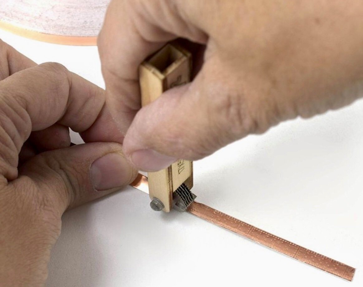
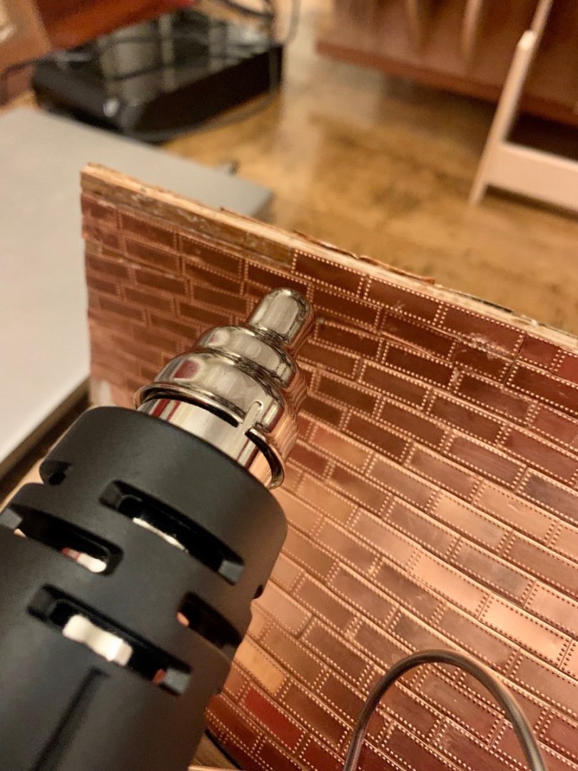
Hi Allan, I’ve also seen the single edge approach and agree it looks good. Artesania Latina market two PE rivet tools, I’m thinking one of these could be modified to produce a single edge pattern, their multi wheel approach also allows for the infill nails to be simulated, the rivet points on the inner and outer wheels are at separate pitches allowing the different nail patterns to be produced. I may need to buy 2 to get the number wheels I would need, but I’ll see. Photos below. I’ve also trialed using heat to de-bond both copper plates and planking, and initial trials are good, which is a positive for future modifications. Gary


-
Thanks Dave, I’ll be going backwards before going forwards first, but with some planning and forethought I should get her moving in the right direction. Gary
-
Hi Allan, There is very little on copper plating, obviously sizes and plate gauge are known, but as to lay-patterns, nothing unfortunately. I agree on the scale issue of copper plates, I am going to experiment with the new AL plate parking tool, but getting the representation right will be difficult. Just getting the overlap of plates at scale without creating an obvious clunky series of ridges is almost impossible, the plates would have to be as thin as tissue paper. There are plenty of photos to draw from, I have many from the Victory and Trincomalee so do have the visual template, simulating it 🤔 Gary
-
The information is in the PDF, but a brief overview: The history of Victory’s restoration to her Trafalgar condition has for the last century been hampered by financial constraints, the placing of pre-conceptions over evidence, politics, and domination by strong characters. This has always resulted in compromises that leads us to where we are today. When her great restoration began 101 years ago Great Britain was gripped by post war economic constraints, so very little money was forthcoming from the Admiralty, the Society for Nautical Research had stepped in and raised funds to finance for the restoration, and appointed an advisory technical committee to oversee this. Unfortunately this committee had two differing schools of thought, one side wanted to see her restored essentially to the ‘beauty’ of her as-launched condition, the other side went with the records available, these sides couldn’t be reconciled. In essence we ended up with something similar to her Trafalgar Stern, and something similar to her as-launched bow, but with a near representation of her Trafalgar figurehead. Everything in between was a similar mix. Money was also a factor, and when reopened to the public in 1928 the ship was fairly bare of fittings, however, the ship had been saved, and that is the main benefit. Unfortunately the 1920’s restoration essential locked-in place the major elements of the ship, and that continues to influence subsequent works. Several cycles of poor restoration, WW2 bomb damage, and many decades of death watch beetle infestation have soaked up vast amounts of money just to keep the structure in place, but this money may otherwise have gone to research and interpretation. I am hopeful the current restoration will arrest some of these issues, but I don’t see any structural changes to the form of the ship, they would be too intrusive and costly. Gary
- 2 replies
-
- 3
-
-
- HMS Victory
- Caldercraft
- (and 1 more)
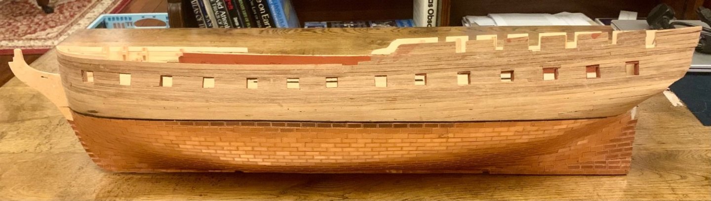
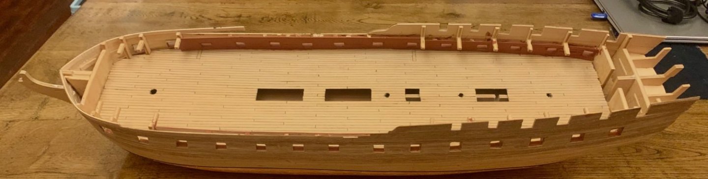
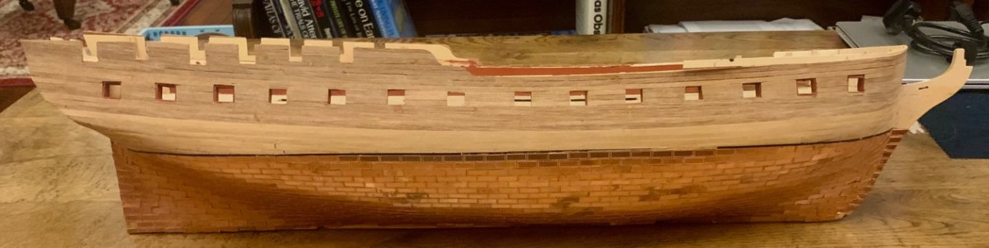
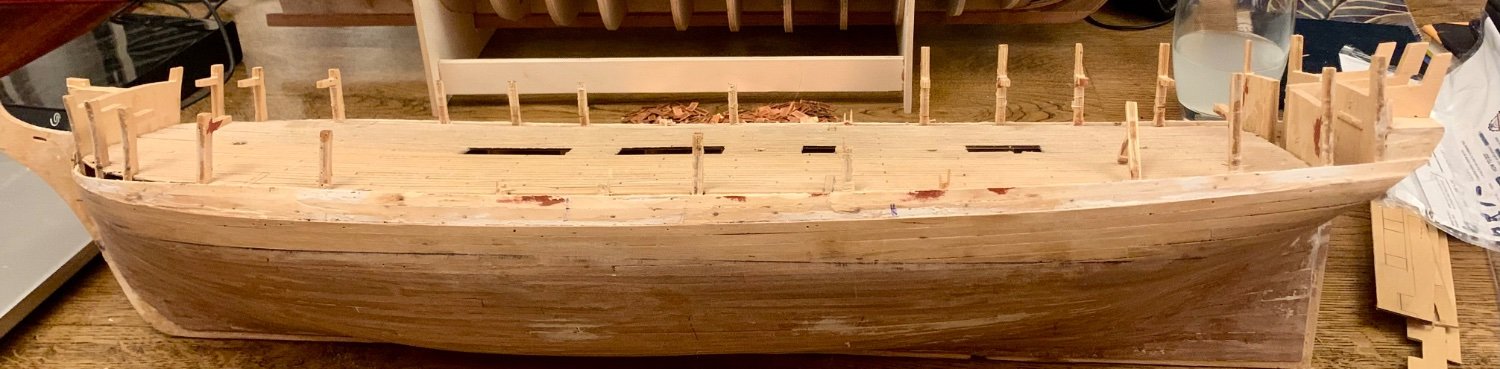
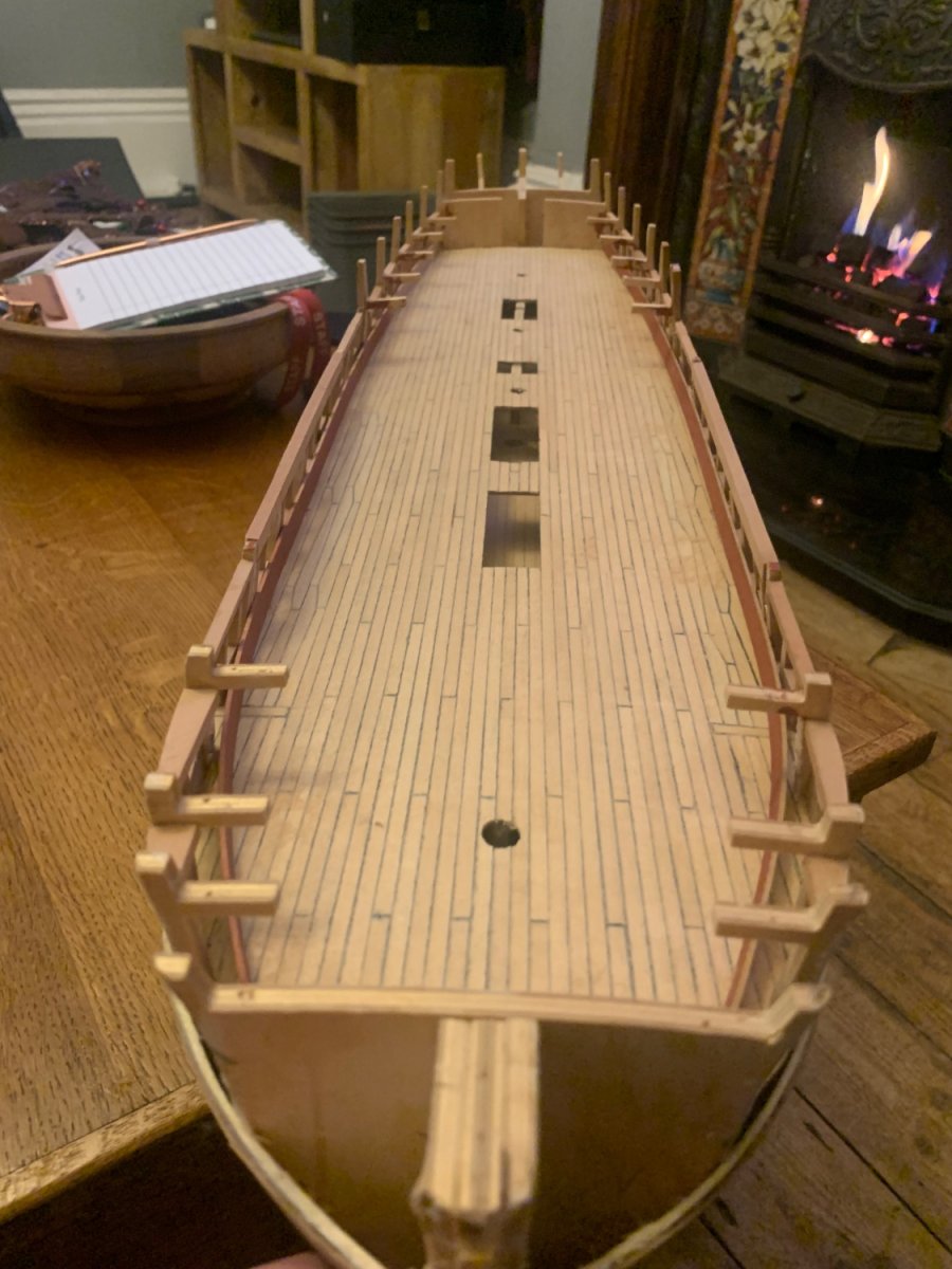
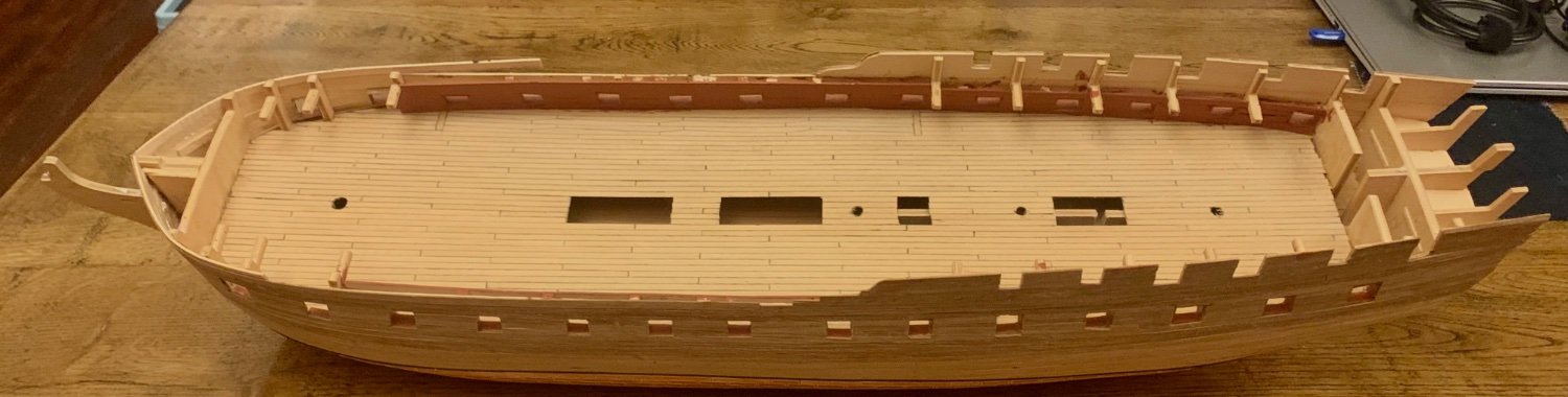
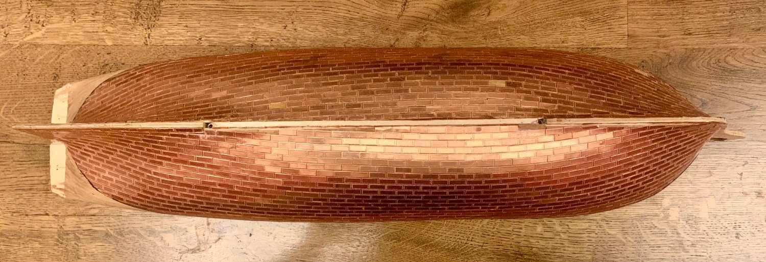
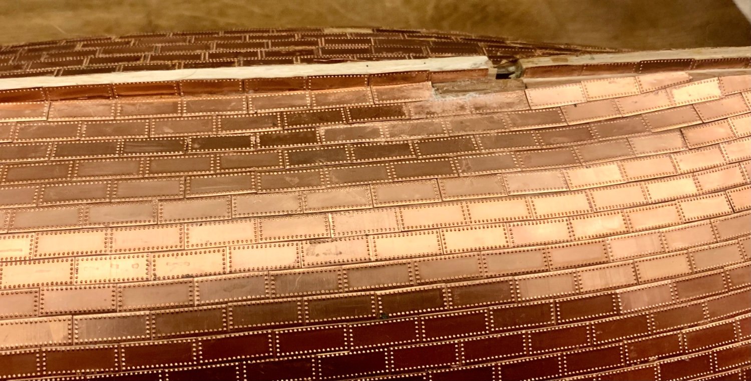
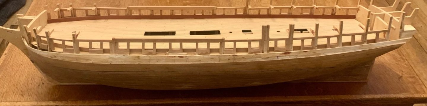
-
Somewhile back ‘Shipyard Sid’, aka Dave, found himself in the position of having to look for someone to take over the build of his HMS Diana for reasons he has already stated on this site elsewhere. Looking back at the relevant posts I had obviously missed these at the time, however, living only a mile or so away Dave recently asked me if I would like to take on the model. Diana has been on my wish list but wasn’t in my immediate contemplation. I have my Victory research which I just completed and have undertaken to publish on this site and have also very recently commenced the associated build of the Victory based on Caldercraft’s 1:72 scale kit, alongside the recently released Artesania Latina Cross Section of the same scale as a complementary pair (build log imminent). I also have a backlog of completing my scratch 1:64 HMS Trincomalee and Chuck’s Winnie also begging for a start as well, so no shortage of projects. So, what’s one more to add to the collection😊. I must admit that this hobby is getting like the Admiral’s DIY list which out-competes model building for my time, it seems only to get longer the more I do! But who wants to be bored. I think I will try to complete this simultaneously with the Victory but may take a few weeks to get up and running – that DIY list is pressing apparently, seems there is some artificial need to have completed certain milestones by Xmas, I have never understood that link, but it may be why DIY stores stock Xmas decorations. Happy for someone to explain the causal link between the two, but I undertake to wilfully remain sceptical of the whatever wafer-thin explanation someone can dream up! Back to Diana, obviously I have said yes. It is a shame Dave feels he can’t complete the Diana to the standard he desires, when I picked up the model, I also got to see his Caldercraft Victory he completed some years back and it is a wonderful example to behold, which he should be rightly proud off. I’ve enclosed below some photos of where Dave had got to with the Diana. As he pointed out to me, there is the need to do some remedial work, primarily to the copper plating, and on a cursory examination some of the gunports also need some attention. Some of the copper plates have come off, and some others are in the process of exfoliating themselves, bearing in mind Dave hasn’t touched tis for at least 2 years. In terms of the main deck gunports some of these need realigning. I think I will start with the copper plating, remove any damaged and loose plates and those that require some realignment. Dave fastened these to the ship with Evo Stick, so hopefully a combination of acetone and heat (not at the same time!) should loosen these. I’ll just see where the process takes me. For the planking I plan on removing all the inner planking and then establishing the high and low points of the all the gunports relative to the deck for the outer planking so as to determine how many strakes are involved in the realignment process. Hopefully I can just remove the planks within those limits, re-establish the gunport openings and make good the planking. Gary